
Related Manuals for Kramer VS-3232DN-EM


Summary of Contents for Kramer VS-3232DN-EM
- Page 1 USER MANUAL MODEL: VS-3232DN-EM 4x4 to 32x32 Modular Multi-Format Managed Digital Matrix Switcher P/N: 2900-300932 Rev 3 www.KramerAV.com...
-
Page 2: Table Of Contents
Overview Mounting VS-3232DN-EM Connecting the VS-3232DN-EM Port Numbering Connecting to the VS-3232DN-EM via RS-232 Connecting to the VS-3232DN-EM via USB (VCOM) Connecting to the VS-3232DN-EM via Ethernet Operating Your Video Matrix Switcher Startup Display Using the Selector Buttons Confirming Actions... - Page 3 Kramer Electronics Ltd. Protocol 3000 Understanding Protocol 3000 Commands Protocol 3000 Syntax Protocol 3000 Commands Using the Packet Protocol VS-3232DN-EM – Contents...
-
Page 4: Introduction
Kramer Electronics Ltd. Introduction Welcome to Kramer Electronics! Since 1981, Kramer Electronics has been providing a world of unique, creative, and affordable solutions to the vast range of problems that confront the video, audio, presentation, and broadcasting professional on a daily basis. In recent years, we... -
Page 5: Getting Started
• AAD-IN4-F32 / AAD-OUT4-F32 (see Defining the AAD-IN4-F32 / AAD-OUT4-F32 on page 64). The F670-IN4/OUT4-F32 cards are fully compatible with the Kramer 670T/670R and 671T/671R HDMI/DVI transmitters and receivers for non-HDCP content. Getting Started We recommend that you: • Unpack the equipment carefully and save the original box and packaging materials for possible future shipment. -
Page 6: Safety Instructions
European Advanced Recycling Network (EARN) and will cover any costs of treatment, recycling and recovery of waste Kramer Electronics branded equipment on arrival at the EARN facility. For details of Kramer’s recycling arrangements in your particular country go to our recycling pages at www.kramerav.com/support/recycling. -
Page 7: Overview
For example, you can configure a device as a 4 x 24 or a 32 x 8 matrix switcher to exactly suit your needs. VS-3232DN-EM – Introduction... - Page 8 • Non-volatile EDID storage. • Kramer Core™ – Flexible infrastructure conversion. Copper, fiber or Twisted Pair, all can be used at the same time according to input/output module selection. The matrix receives signals from compatible Kramer transmitters, automatically converts between available infrastructure options and sends the signals to compatible Kramer receivers.
- Page 9 • The infrared remote control transmitter (future). • Kramer Network enterprise management platform. VS-3232DN-EM is a sophisticated device but has nevertheless been designed to be simple to operate using an intuitive front panel keypad. For details of how to route inputs to...
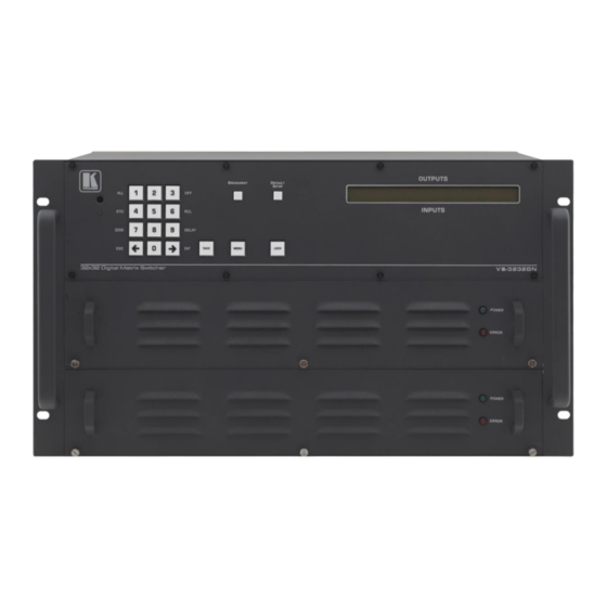
- Page 10 Defining the VS-3232DN-EM 4x4 to 32x32 Modular Multi-Format Managed Digital Matrix Switcher This section defines the front and rear panels of the VS-3232DN-EM. Figure 1: VS-3232DN-EM Front Panel Buttons 14, 15 and 16 function as the TAKE, MENU and LOCK buttons respectively.
- Page 11 ERROR LED Lights red when an error is detected. Briefly lights red immediately following a power disruption (e.g., cable disconnection, power off, and so on). Figure 2: VS-3232DN-EM Front Panel Numeric Keypad Feature Function ◄ (Backward) Press to shift the display right (the LCD display only shows 13 cross-points out of a total of 32).
- Page 12 Kramer Electronics Ltd. Figure 3: VS-3232DN-EM Rear Panel Showing DVI cards Feature Function AC Mains Power Module Fuse holder and power cord socket. Connect to the AC mains supply. RESET Button Press to restart the VS-3232DN-EM. USB Virtual COM Port...
- Page 13 Kramer Electronics Ltd. Feature Function Test Module DVI Molex 24- Connect to one of the relevant video inputs/outputs to aid in pin Video Connector troubleshooting (see Using the Test Module to Troubleshoot Video Problems on page 69). VS-3232DN-EM – Introduction...
-
Page 14: Mounting Vs-3232Dn-Em
Kramer Electronics Ltd. Mounting VS-3232DN-EM This section provides instructions for mounting VS-3232DN-EM. Before installing, verify that the environment is within the recommended range: • Operation temperature – 0 to 40C (32 to 104F). • Storage temperature – -40 to +70C (-40 to +158F). -
Page 15: Connecting The Vs-3232Dn-Em
Kramer Electronics Ltd. Connecting the VS-3232DN-EM Always switch off the power to each device before connecting it to your VS-3232DN-EM. After connecting your VS-3232DN-EM, connect its power and then switch on the power to each device. You do not have to connect all the inputs and outputs, connect only those that are required. In the following example, only two inputs and two outputs are connected. - Page 16 Kramer Electronics Ltd. Figure 4: Connecting the VS-3232DN-EM VS-3232DN-EM – Connecting the VS-3232DN-EM...
-
Page 17: Port Numbering
OUT 1, OUT 2, OUT 3, OUT 4 OUT 5, OUT 6, OUT 7, OUT 8 OUT 9, OUT 10 There is no IN 7, IN 8, OUT 11, or OUT 12 because these slots contain DVI dual link cards. VS-3232DN-EM – Connecting the VS-3232DN-EM... -
Page 18: Connecting To The Vs-3232Dn-Em Via
(only pin 2 to pin 2, pin 3 to pin 3, and pin 5 to pin 5 need to be connected) to the RS-232 9-pin D-sub port on your PC. Connecting to the VS-3232DN-EM via USB (VCOM) The device’s USB port can work as a virtual COM (VCOM) port. Verify that the USB port on... -
Page 19: Connecting To The Vs-3232Dn-Em Via Ethernet
Kramer Electronics Ltd. Connecting to the VS-3232DN-EM via Ethernet You can connect to the VS-3232DN-EM via Ethernet using either of the following methods: • Directly to the PC using a crossover cable (see Connecting the Ethernet Port Directly to a PC on page 16). - Page 20 Figure 8: Internet Protocol Version 4 Properties Window Figure 9: Internet Protocol Version 6 Properties Window 6. Select Use the following IP Address for static IP addressing and fill in the details as shown in Figure VS-3232DN-EM – Connecting the VS-3232DN-EM...
-
Page 21: Connecting The Ethernet Port Via A Network Hub Or Switch
Connecting the Ethernet Port via a Network Hub or Switch You can connect the Ethernet port of the VS-3232DN-EM to the Ethernet port on a network hub or using a straight-through cable with RJ-45 connectors. VS-3232DN-EM – Connecting the VS-3232DN-EM... -
Page 22: Operating Your Video Matrix Switcher
Instead, the front panel includes a numeric keypad within the Selector Buttons area (see Defining the VS-3232DN-EM 4x4 to 32x32 Modular Multi-Format Managed Digital Matrix Switcher on page 7). This numeric keypad lets you enter both the output and input numbers... -
Page 23: Using The Selector Buttons
In the Confirm mode: • The TAKE button lights. • You enter an action and then confirm it by pressing the TAKE button. • Every action requires user confirmation, protecting against erroneous actions. VS-3232DN-EM – Operating Your Video Matrix Switcher... -
Page 24: Switching Actions
The left-hand side of the display shows a section of the output/input display automatically sliding the content to include output 12. 2. Using the numeric keypad, enter the required input (in this example, 14): VS-3232DN-EM – Operating Your Video Matrix Switcher... -
Page 25: Switching Several Inputs To Several Outputs
3. Use the numeric keypad to turn the required output off. The output is turned off. To turn an output off in the Confirm mode: • Repeat the steps above and then press the flashing TAKE button to confirm the action. VS-3232DN-EM – Operating Your Video Matrix Switcher... -
Page 26: Locking The Front Panel Buttons
Press and hold LOCK until the button lights. The front panel buttons are locked. To unlock the front panel buttons: • Press and hold LOCK until the button is no longer lit. The front panel buttons are unlocked. VS-3232DN-EM – Operating Your Video Matrix Switcher... -
Page 27: Using The Configuration Menus
Setup Menu—4: store setup XX, Storing the Setup in a Preset on page 27). • 6: recall setup XX, recalling a preset (see Setup Menu—6: recall setup XX, Recalling a Preset on page 28). VS-3232DN-EM – Using the Configuration Menus... - Page 28 3. Using the numeric keys, enter the output to be turned off. The TAKE button flashes. 4. Press TAKE. The selected output is turned off. The display reverts to the output/input display showing that the selected output is turned off with the input being blank. VS-3232DN-EM – Using the Configuration Menus...
- Page 29 To view the EDID assignments: 1. Press MENU. The Setup Menu options are displayed. 2. Press 7 (EDID) on the numeric keypad (see Figure The following is displayed: SETUP EDID ENT to View EDID and Set EDID VS-3232DN-EM – Using the Configuration Menus...
- Page 30 3. Using the numeric keys, enter the preset (1 to 60) in which to store the current setup. The following is displayed: Wait ….. After a few seconds, if the preset is not empty, the following is displayed: SETUP NOT EMPTY CONFIRM The TAKE button flashes. VS-3232DN-EM – Using the Configuration Menus...
-
Page 31: Using The Config Menu
(Config Menu—Display Firmware Versions on page 33). To enter the Config Menu: • Press MENU twice. The MENU button lights and the following message is displayed: Start configuration menu MENU to view setups ENT to change them VS-3232DN-EM – Using the Configuration Menus... - Page 32 (see Using the Input / Output Cards on page for information on the input / output cards and their parameters). VS-3232DN-EM – Using the Configuration Menus...
- Page 33 11. Do one of the following: ▪ Press BREAKAWAY to exit the Config Menu. ▪ Wait approximately 15 seconds for the operation to time out. ▪ Press MENU to exit to the parameter list. VS-3232DN-EM – Using the Configuration Menus...
- Page 34 3. Press TAKE to enter the list of ports. The cursor flashes on a selected port. 4. Select the required port to modify using the left and right arrow buttons. VS-3232DN-EM – Using the Configuration Menus...
- Page 35 2. Press MENU until the following is displayed: store DEFAULT setup press ENT to store 3. Press ENT to store the current configuration as the default configuration. The following is displayed: current matrix stage is OKAY? press TAKE to confirm VS-3232DN-EM – Using the Configuration Menus...
- Page 36 This option displays the main and front firmware versions. To display the firmware versions: 1. Press MENU twice. The following message is displayed: start configuration menu MENU to view setup ENT to change them VS-3232DN-EM – Using the Configuration Menus...
- Page 37 2. Press MENU until the following is displayed: Main Firmware Version: Front Firmware Version: 3. Either: ▪ Press BREAKAWAY to exit the Config Menu. ▪ Wait approximately 15 seconds for the operation to time out. VS-3232DN-EM – Using the Configuration Menus...
-
Page 38: Configuring The Number Of Installed Input And Output Ports
5. Reboot the device by turning the power off and then on again. If you customized the number of displayed ports before installing a new module, you may need to re-customize the displayed ports to reflect your hardware change. VS-3232DN-EM – Configuring the Number of Installed Input and Output Ports... -
Page 39: Using The Test Video Card
The test module generates a range of both PC and HD resolutions which are selected by a combination of DIP-switches and an on-board jumper (labeled B3). Install the jumper to select HD resolutions or remove the jumper to select PC resolutions. VS-3232DN-EM – Using the Test Video Card... -
Page 40: Setting The Pattern Of The Generated Video
32 inputs and 32 outputs, you must configure the VS-3232DN-EM as 33 x 33 To install the test module in the configuration: 1. Press ESC, ENT and LOCK together. The following is displayed: Configuration Device VS-3232DN-EM – Using the Test Video Card... - Page 41 5. Increase the number of configured inputs and outputs by one (see Configuring the Number of Installed Input and Output Ports on page 35). 6. Power cycle the device. The test module is now installed and may be used. VS-3232DN-EM – Using the Test Video Card...
-
Page 42: Using The Input / Output Cards
(Fast Switch or Normal Switch). Switch Reset Re-power: power cycle the port. Re-power Output Factory default: perform a factory reset of the port to default values. VS-3232DN-EM – Using the Input / Output Cards... -
Page 43: Defining The Uhda-In4-F32 / Uhda-Out4-F32
On the top and third jacks, select embedded, de-embedded or ARC. ▪ On the second and bottom jacks, select embedded or de-embedded. • EDID capture: Copies and stores the EDID from a display device. VS-3232DN-EM – Using the Input / Output Cards... - Page 44 MUTE Non-MUTE: unmutes the audio output. Note: When set to Mute, any change to the audio parameters automatically sets this to unmute. Audio Mono OFF—Analog output is stereo. MIX—Analog output is mono. VS-3232DN-EM – Using the Input / Output Cards...
- Page 45 0.23 kg (0.51 lbs) approx. SHIPPING WEIGHT: 0.37 kg (0.82 lbs) approx. STANDARD COMPLIANCE: HDCP 1.4, HDMI 1.4, HDTV compatible SAFETY REGULATORY COMPLIANCE: ENVIRONMENTAL REGULATORY Complies with appropriate requirements of RoHs and WEEE COMPLIANCE: VS-3232DN-EM – Using the Input / Output Cards...
-
Page 46: Defining The Dt-In4-F32 / Dt-Out4-F32
(Fast Switch or Normal Switch). Switch DT-IN4-F32 / DT-OUT4-F32 Technical Specifications HDBT cards must be used with twisted pair cables with RJ-45 connections, such as Kramer BC-UNIKAT shielded twisted pair (U/FTP) cables. VS-3232DN-EM – Using the Input / Output Cards... -
Page 47: Defining The Dtaxr-In4-F32 / Dtaxr-Out4-F32
The DTAxr-OUT4-F32 is a 4-output 4K60 4:2:0 HDMI over HDBaseT card with selectable embedded or de-embedded analog audio (F-32). The DTAxr-OUT4-F32 outputs four extended reach HDBaseT signals with analog audio, bidirectional RS-232, and IR from the chassis to the line. VS-3232DN-EM – Using the Input / Output Cards... - Page 48 Enables range extender. Off for distances of up to 100m at 4K@60Hz 4:2:0 or 4K@30Hz 4:4:4 or up to 130m at 2K; On for distances of up to 180m at 1080p @60Hz @24bpp. *0:ON, 1:OFF. Note: Distances are valid when using Kramer BC-UNIKAT cables. Reset Input Re-power: power cycle the port. Re-power Factory Default: perform a factory reset of the port to default values.
- Page 49 Note: Not applicable when the audio port is set to output (ST=1). DTAxr-IN4-F32 / DTAxr-OUT4-F32 Technical Specifications HDBT cards must be used with twisted pair cables with RJ-45 connections, such as Kramer BC-UNIKAT shielded twisted pair (U/FTP) cables. The following table defines the technical specifications.
-
Page 50: Defining The Hdbt-In4-F32 / Hdbt-Out4-F32
C-A35M/IRRN. For information on the IR wiring scheme, see IR Wiring Scheme for HDBT Cards on page 49. For information on connecting via RS-232, see Connecting to the VS-3232DN-EM via RS-232 on page 15. VS-3232DN-EM – Using the Input / Output Cards... - Page 51 Note: Distances are valid when using Kramer BC-UNIKAT cables. HDBT-IN4-F32 / HDBT-OUT4-F32 Technical Specifications HDBT cards must be used with twisted pair cables with RJ-45 connections, such as Kramer BC-UNIKAT shielded twisted pair (U/FTP) cables. The following table defines the technical specifications.
- Page 52 The terminal block size and supplied connector differs according to the type of HDBT card. However, the wiring scheme for connecting the IR emitter / receiver is the same for all HDBT cards. VS-3232DN-EM – Using the Input / Output Cards...
-
Page 53: Defining The H-In4-F32 / H-Out4-F32
6.75Gbps MAXIMUM RANGE: 15m (49ft) 3D PASS THROUGH: Supported POWER CONSUMPTION: Input / Output card: 9W OPERATING TEMPERATURE: 0° to +40°C (32° to 104°F) –40° to +70°C (–40° to 158°F) STORAGE TEMPERATURE: VS-3232DN-EM – Using the Input / Output Cards... -
Page 54: Defining The Had-In4-F32 / Had-Out4-F32
RCA port. When present, AUD-Digital is selected, when absent, AUD- Embedded is selected. AUD-Embedded—HDMI audio is selected. AUD-Digital—S/PDIF audio is selected. Reset Input Re-power—Power cycles the port. Factory—Performs a factory reset to default values of the port. VS-3232DN-EM – Using the Input / Output Cards... - Page 55 0.3 kg (0.67 lbs) approx. SHIPPING WEIGHT: 0.47 kg (1.04 lbs) approx. STANDARD COMPLIANCE: HDCP 1.4, HDMI 1.3a SAFETY REGULATORY COMPLIANCE: ENVIRONMENTAL REGULATORY Complies with appropriate requirements of RoHs and COMPLIANCE: WEEE VS-3232DN-EM – Using the Input / Output Cards...
-
Page 56: Defining The Haa-In4-F32 / Haa-Out4-F32
MUTE—Mutes the audio input. Non-MUTE Non-MUTE—Unmutes the audio input. Note: Not applicable when digital audio is selected. Audio Select Auto Auto AUD-Embedded—HDMI audio is selected. AUD-Analog—Analog audio from the 3.5mm mini jack is selected. VS-3232DN-EM – Using the Input / Output Cards... - Page 57 –40° to +70°C (–40° to 158°F) STORAGE TEMPERATURE: HUMIDITY: 10% to 90%, RHL non-condensing 22cm x 18.8cm x 2cm (8.7” x 7.4” x 0.8”) W, D, H DIMENSIONS: PRODUCT WEIGHT: 0.28 kg (0.62 lbs) approx. VS-3232DN-EM – Using the Input / Output Cards...
-
Page 58: Defining The Hdcp-In4-F32 / Hdcp-Out4-F32
0.26 kg (0.57 lbs) approx. SHIPPING WEIGHT: 0.4 kg (0.88 lbs) approx. STANDARD COMPLIANCE: HDCP, HDMI SAFETY REGULATORY COMPLIANCE: CE, FCC ENVIRONMENTAL REGULATORY Complies with appropriate requirements of RoHs and COMPLIANCE: WEEE VS-3232DN-EM – Using the Input / Output Cards... -
Page 59: Defining The Dgkat-In4-F32 / Dgkat-Out4-F32
DGKat-IN4-F32 / DGKat-OUT4-F32 Technical Specifications DGKat cards must be used with shielded twisted pair cables with RJ-45 connections, such as the Kramer BC-UNIKAT. For more information, see the DGKat Installation Guide. DGKat cards support Deep Color only at resolutions of 720p and lower. - Page 60 Serial data present on the RS-232 port of a DGKat input /output card is not transmitted via the switcher. This data is transmitted over the TP cable of the same input / output card (see Figure 14). Figure 14: DGKat Card Serial Data Transmission VS-3232DN-EM – Using the Input / Output Cards...
-
Page 61: Defining The F670-In4-F32 / F670-Out4-F32
Kramer Electronics Ltd. Defining the F670-IN4-F32 / F670-OUT4-F32 F670 cards are fully compatible with the Kramer 670T/670R and 671T/671R HDMI/DVI transmitters and receivers for non-HDCP content. The F670-IN4-F32 is a 4-Input HDMI over OM3 Fiber Card (F-32): The F670-OUT4-F32 is a 4-Output HDMI over OM3 Fiber Card (F-32):... -
Page 62: Defining The F610-In4-F32 / F610-Out4-F32
400m (1310ft) using Multi Mode OM2 fiber 3D PASS THROUGH: Not supported POWER CONSUMPTION: Input card: 5W Output card: 7W OPERATING TEMPERATURE: 0° to +40°C (32° to 104°F) –40° to +70°C (–40° to 158°F) STORAGE TEMPERATURE: VS-3232DN-EM – Using the Input / Output Cards... -
Page 63: Defining The Dvi-In4-F32 / Dvi-Out4-F32
22cm x 18.8cm x 2cm (8.7” x 7.4” x 0.8”) W, D, H DIMENSIONS: PRODUCT WEIGHT: 0.23 kg (0.51 lbs) approx. SHIPPING WEIGHT: 0.37 kg (0.82 lbs) approx. STANDARD COMPLIANCE: DVI 1.0 VS-3232DN-EM – Using the Input / Output Cards... -
Page 64: Defining The Dl-In2-F32 / Dl-Out2-F32
0.23 kg (0.51 lbs) approx. SHIPPING WEIGHT: 0.37 kg (0.82 lbs) approx. STANDARD COMPLIANCE: DVI 1.0 SAFETY REGULATORY COMPLIANCE: CE, FCC ENVIRONMENTAL REGULATORY Complies with appropriate requirements of RoHs and COMPLIANCE: WEEE VS-3232DN-EM – Using the Input / Output Cards... -
Page 65: Defining The Sdia-In4-F32
The card stores the current option for each port. The following table describes the values in the SDI_AUDIO_SWITCH menu: Value SDI Audio Number Description Group # Channel Pair # 2 channels (Stereo) VS-3232DN-EM – Using the Input / Output Cards... - Page 66 22cm x 18.8cm x 2cm (8.7” x 7.4” x 0.8”) W, D, H DIMENSIONS: PRODUCT WEIGHT: 0.32 kg (0.71 lbs) approx. SHIPPING WEIGHT: 0.47 kg (1.04 lbs) approx. STANDARD COMPLIANCE: SAFETY REGULATORY COMPLIANCE: ENVIRONMENTAL REGULATORY Complies with appropriate requirements of RoHs and COMPLIANCE: WEEE VS-3232DN-EM – Using the Input / Output Cards...
-
Page 67: Defining The Vgaa-In4-F32 / Vgaa-Out4-F32
The VGAA-IN4-F32 is a 4-Input VGA with Analog Audio Card (F-32): The VGAA-OUT4-F32 is a 4-Output VGA with Analog Audio Card (F-32): Audio output is accessed by connecting the four supplied Kramer C-GF/GMAF-30 cables to each VGA port as illustrated in... - Page 68 (Ex-fast Switch, Fast Switch or Switch Normal Switch). Volume Sets the audio output volume (0–70). Audio Balance Sets the audio output channel balance (0–100). Audio Bass Sets the audio output bass level (0–15). VS-3232DN-EM – Using the Input / Output Cards...
- Page 69 0.25 kg (0.55 lbs) approx. SHIPPING WEIGHT: 0.42 kg (0.93 lbs) approx. STANDARD COMPLIANCE: SAFETY REGULATORY COMPLIANCE: ENVIRONMENTAL REGULATORY Complies with appropriate requirements of RoHs and WEEE COMPLIANCE: INCLUDED ACCESSORIES: 4 C-GF/GMAF-30 cables VS-3232DN-EM – Using the Input / Output Cards...
-
Page 70: Defining The Aad-In4-F32 / Aad-Out4-F32
Sets the audio output bass level (0–15). Note: Not applicable when digital audio is selected. Audio Sets the audio output treble level (0–15). Treble Note: Not applicable when digital audio is selected. VS-3232DN-EM – Using the Input / Output Cards... - Page 71 22cm x 18.8cm x 2cm (8.7” x 7.4” x 0.8”) W, D, H DIMENSIONS: PRODUCT WEIGHT: 0.31 kg (0.68 lbs) approx. SHIPPING WEIGHT: 0.48 kg (1.06 lbs) approx. SAFETY REGULATORY COMPLIANCE: ENVIRONMENTAL REGULATORY Complies with appropriate requirements of RoHs and COMPLIANCE: WEEE VS-3232DN-EM – Using the Input / Output Cards...
-
Page 72: Using The Test Module To Troubleshoot Video Problems
36). 4. Set the pattern for the generated video (see Setting the Pattern of the Generated Video on page 37). 5. Verify that the projector output is as expected. VS-3232DN-EM – Using the Test Module to Troubleshoot Video Problems... -
Page 73: Testing The Output Signal Path To The Projector
36). 6. Set the pattern for the generated video (see Setting the Pattern of the Generated Video on page 37). 7. Verify that the projector output is as expected. VS-3232DN-EM – Using the Test Module to Troubleshoot Video Problems... -
Page 74: Input / Output Card Hardware Installation Instructions
1. Power off the VS-3232DN-EM and all devices connected to it. 2. Using a Phillips screwdriver, loosen the screws at the top and bottom of the blanking plate (see Figure 18). VS-3232DN-EM – Input / Output Card Hardware Installation Instructions... - Page 75 8. Using a Phillips screwdriver, tighten the retaining screws at the top and bottom of the card to secure it to the chassis. 9. Power on the VS-3232DN-EM. 10. Power on the peripheral devices. VS-3232DN-EM – Input / Output Card Hardware Installation Instructions...
-
Page 76: Installing A Ps-1Dn Power Supply
The power supply is seated firmly in place – the front panel of the power supply is flush with the front panel of the chassis and the screws are tightly fastened. If the problem persists, or if the red ERROR LED is always lit, contact Kramer technical support. -
Page 77: Upgrading The Vs-3232Dn-Em Firmware
VS-3232DN-EM enables upgrading device and card firmware via RS-232, USB (VCOM) or Ethernet using the K-Upload software application, available at www.kramerav.com/product/VS-3232DN-EM. For instructions on upgrading the firmware using K-Upload, see the K-Upload User Manual. For information on connecting to the... -
Page 78: Upgrading Firmware Using Kramer Network
Ethernet using the Kramer Network enterprise management platform, available at www.kramerav.com/product/VS-3232DN-EM. For instructions on upgrading the firmware using Kramer Network, see the Kramer Network User Manual. For information on connecting to the VS-3232DN-EM... -
Page 79: Technical Specifications
ENVIRONMENTAL REGULATORY Complies with appropriate requirements of RoHs and COMPLIANCE: WEEE INCLUDED ACCESSORIES: Power cord, Infrared remote control transmitter Specifications are subject to change without notice at www.kramerav.com Quick VS-3232DN-EM Card Comparison Card Ports BW per Max. Range Compliance Channel Pass Thru 10m (32ft) –... - Page 80 200m (655ft) – jack connectors 4 SDI, 75Ω on BNC HD 1080p 90m (295ft) – connectors 3G 1080p VGAA 4 VGA on 15-pin HD 450MHz 10m (32ft) connectors 4 unbalanced analog audio on 3.5mm mini jack connectors** VS-3232DN-EM – Technical Specifications...
- Page 81 4 S/PDIF (digital audio) on RCA connectors 4 balanced audio stereo (analog audio) on 5- pin terminal blocks * When using BC-UNIKAT cables. ** Accessible via C-GF/GMAF-30 cables. Specifications are subject to change without notice at www.kramerav.com VS-3232DN-EM – Technical Specifications...
-
Page 82: Default Settings
832 x 624p at 75Hz - Apple Mac II 1024 x 768i at 87Hz - IBM 1024 x 768p at 60Hz - VESA 1024 x 768p at 70Hz - VESA 1024 x 768p at 75Hz - VESA 1280 x 1024p at 75Hz - VESA VS-3232DN-EM – Default Settings... - Page 83 Additional descriptors... None Preferred timing..Yes Native/preferred timing.. 1280x720p at 60Hz (16:10) Modeline...."1280x720" 74.250 1280 1390 1430 1650 720 725 730 750 +hsync +vsync Standard timings supported 720 x 400p at 70Hz - IBM VGA VS-3232DN-EM – Default Settings...
- Page 84 Power management..Standby, Suspend, Active off/sleep Extension blocs..1 (CEA-EXT) ------------------------- DDC/CI....Not supported Color characteristics Default color space..Non-sRGB Display gamma.... 2.20 Red chromaticity..Rx 0.674 - Ry 0.319 Green chromaticity..Gx 0.188 - Gy 0.706 VS-3232DN-EM – Default Settings...
- Page 85 Raw data 00,FF,FF,FF,FF,FF,FF,00,2D,B2,00,12,01,01,01,01,14,1B,01,03,80,34,20,78,E2,B3,25,AC,51,30,B4,26, 10,50,54,FF,FF,80,81,8F,81,99,A9,40,61,59,45,59,31,59,71,4A,81,40,01,1D,00,72,51,D0,1E,20,6E,28, 55,00,07,44,21,00,00,1E,00,00,00,FF,00,32,39,35,2D,38,38,33,34,35,30,31,30,30,00,00,00,FC,00,56, 53,2D,33,32,44,54,0A,20,20,20,20,20,00,00,00,FD,00,38,4C,1E,53,11,00,0A,20,20,20,20,20,20,01,EA, 02,03,1B,C1,23,09,07,07,48,10,05,84,03,02,07,16,01,65,03,0C,00,10,00,83,01,00,00,02,3A,80,18,71, 38,2D,40,58,2C,45,00,07,44,21,00,00,1E,01,1D,80,18,71,1C,16,20,58,2C,25,00,07,44,21,00,00,9E,01, 1D,00,72,51,D0,1E,20,6E,28,55,00,07,44,21,00,00,1E,8C,0A,D0,8A,20,E0,2D,10,10,3E,96,00,07,44,21, 00,00,18,00,00,00,00,00,00,00,00,00,00,00,00,00,00,00,00,00,00,00,00,00,00,00,00,00,00,00,00,77 DTAxr-IN4-F32 / DTAxr-OUT4-F32 Monitor Model name....VS-32DTAXR Manufacturer..... KMR Plug and Play ID..KMR1200 Serial number.... 295-883450100 Manufacture date..2017, ISO week 20 Filter driver.... None VS-3232DN-EM – Default Settings...
- Page 86 Rear center....No Front left/right center.. No Rear left/right center... No Rear LFE....No Report information Date generated... 2/28/2018 Software revision..2.90.0.1020 Data source....Real-time 0x0072 Operating system..10.0.16299.2 Raw data 00,FF,FF,FF,FF,FF,FF,00,2D,B2,00,12,01,01,01,01,14,1B,01,03,80,34,20,78,E2,B3,25,AC,51,30,B4,26, 10,50,54,FF,FF,80,81,8F,81,99,A9,40,61,59,45,59,31,59,71,4A,81,40,01,1D,00,72,51,D0,1E,20,6E,28, 55,00,07,44,21,00,00,1E,00,00,00,FF,00,32,39,35,2D,38,38,33,34,35,30,31,30,30,00,00,00,FC,00,56, 53,2D,33,32,44,54,41,58,52,0A,20,20,00,00,00,FD,00,38,4C,1E,53,11,00,0A,20,20,20,20,20,20,01,5F, 02,03,1B,C1,23,09,07,07,48,10,05,84,03,02,07,16,01,65,03,0C,00,10,00,83,01,00,00,02,3A,80,18,71, VS-3232DN-EM – Default Settings...
- Page 87 NB: NTSC refresh rate = (Hz*1000)/1001 CE audio data (formats supported) LPCM 3-channel, 24-bits at 44/48 kHz CE speaker allocation data Channel configuration..3.0 Front left/right..Yes Front LFE....No Front center..... Yes Rear left/right..No Rear center....No VS-3232DN-EM – Default Settings...
- Page 88 Detailed timing #4..1280x720p at 60Hz (16:9) Modeline...."1280x720" 74.250 1280 1390 1430 1650 720 725 730 750 +hsync +vsync Detailed timing #5..1280x720p at 50Hz (16:9) Modeline...."1280x720" 74.250 1280 1720 1760 1980 720 725 730 750 +hsync +vsync VS-3232DN-EM – Default Settings...
- Page 89 1400 x 1050p at 60Hz - VESA STD 1680 x 1050p at 60Hz - VESA STD 1600 x 1200p at 60Hz - VESA STD EIA/CEA-861 Information Revision number..3 IT underscan..... Not supported Basic audio....Supported VS-3232DN-EM – Default Settings...
- Page 90 800 x 600p at 56Hz - VESA 800 x 600p at 60Hz - VESA 800 x 600p at 72Hz - VESA 800 x 600p at 75Hz - VESA 832 x 624p at 75Hz - Apple Mac II VS-3232DN-EM – Default Settings...
- Page 91 Blue chromaticity..Bx 0.146 - By 0.069 White point (default)..Wx 0.284 - Wy 0.293 Additional descriptors... None Timing characteristics Horizontal scan range..31-94kHz Vertical scan range..50-85Hz Video bandwidth..170MHz CVT standard..... Not supported GTF standard..... Not supported VS-3232DN-EM – Default Settings...
- Page 92 Red chromaticity..Rx 0.640 - Ry 0.341 Green chromaticity..Gx 0.286 - Gy 0.610 Blue chromaticity..Bx 0.146 - By 0.069 White point (default)..Wx 0.284 - Wy 0.293 Additional descriptors... None Timing characteristics Horizontal scan range..31-94kHz VS-3232DN-EM – Default Settings...
- Page 93 55,00,7E,88,42,00,00,1E,02,3A,80,18,71,38,2D,40,58,2C,45,00,C4,8E,21,00,00,1E,00,00,00,FC,00,56, 53,2D,33,32,68,43,61,74,35,65,0A,20,00,00,00,FD,00,32,55,1F,5E,11,00,0A,20,20,20,20,20,20,01,AD, 02,03,1A,71,47,11,13,05,14,84,10,1F,23,0A,06,04,83,05,00,00,65,03,0C,00,10,00,8C,0A,D0,8A,20,E0, 2D,10,10,3E,96,00,58,C2,21,00,00,18,01,1D,80,18,71,1C,16,20,58,2C,25,00,C4,8E,21,00,00,9E,01,1D, 80,D0,72,1C,16,20,10,2C,25,80,C4,8E,21,00,00,9E,01,1D,00,72,51,D0,1E,20,6E,28,55,00,C4,8E,21,00, 00,1E,01,1D,00,BC,52,D0,1E,20,B8,28,55,40,C4,8E,21,00,00,1E,00,00,00,00,00,00,00,00,00,00,00,90 F670-IN4-F32 / F670-OUT4-F32 Monitor Model name....VS-32F670 Manufacturer..... KMR Plug and Play ID..KMR0200 Serial number.... 1 Manufacture date..2014, ISO week 19 Filter driver.... None ------------------------- EDID revision.... 1.3 VS-3232DN-EM – Default Settings...
- Page 94 CE vendor specific data (VSDB) IEEE registration number. 0x000C03 CEC physical address..1.0.0.0 Maximum TMDS clock..165MHz Report information Date generated... 21/01/2015 Software revision..2.80.0.995 Data source....Real-time 0x0071 Operating system..6.1.7601.2.Service Pack 1 Raw data 00,FF,FF,FF,FF,FF,FF,00,2D,B2,00,02,01,00,00,00,13,18,01,03,82,46,27,78,0A,D5,7C,A3,57,49,9C,25, 11,48,4B,FF,FF,80,81,C0,81,00,95,00,81,40,81,80,90,40,B3,00,A9,40,01,1D,00,72,51,D0,1E,20,6E,28, 55,00,7E,88,42,00,00,1E,02,3A,80,18,71,38,2D,40,58,2C,45,00,C4,8E,21,00,00,1E,00,00,00,FC,00,56, 53,2D,33,32,46,36,37,30,0A,20,20,20,00,00,00,FD,00,32,55,1F,5E,11,00,0A,20,20,20,20,20,20,01,A3, VS-3232DN-EM – Default Settings...
- Page 95 NB: NTSC refresh rate = (Hz*1000)/1001 CE audio data (formats supported) LPCM 3-channel, 24-bits at 44/48 kHz CE speaker allocation data Channel configuration..3.0 Front left/right..Yes Front LFE....No Front center..... Yes Rear left/right..No VS-3232DN-EM – Default Settings...
- Page 96 Operating system..6.1.7601.2.Service Pack 1 Raw data 00,FF,FF,FF,FF,FF,FF,00,2D,B2,7C,05,A0,40,00,00,2E,17,01,03,00,46,27,78,0B,D5,7C,A3,57,49,9C,25, 11,48,4B,FF,FF,80,31,40,45,40,61,40,71,4F,81,8F,81,40,81,80,8B,C0,D6,09,80,A0,20,E0,2D,10,10,60, A2,00,04,03,00,00,00,18,02,3A,80,18,71,38,2D,40,58,2C,45,00,10,09,00,00,00,1E,00,00,00,FC,00,56, 53,2D,33,32,56,47,41,41,0A,20,20,20,48,3F,40,30,62,B0,32,40,40,C0,13,00,6F,13,11,00,00,1E,00,4C AAD-IN4-F32 / AAD-OUT4-F32 Monitor Model name....VS-32AAD Manufacturer..... KMR Plug and Play ID..KMR0200 Serial number.... 1 Manufacture date..2014, ISO week 19 Filter driver.... None ------------------------- VS-3232DN-EM – Default Settings...
- Page 97 CE vendor specific data (VSDB) IEEE registration number. 0x000C03 CEC physical address..1.0.0.0 Maximum TMDS clock..165MHz Report information Date generated... 28/12/2015 Software revision..2.70.0.989 Data source....Real-time 0x0071 Operating system..6.1.7601.2.Service Pack 1 Raw data 00,FF,FF,FF,FF,FF,FF,00,2D,B2,00,02,01,00,00,00,13,18,01,03,82,46,27,78,0A,D5,7C,A3,57,49,9C,25, 11,48,4B,FF,FF,80,81,C0,81,00,95,00,81,40,81,80,90,40,B3,00,A9,40,01,1D,00,72,51,D0,1E,20,6E,28, 55,00,7E,88,42,00,00,1E,02,3A,80,18,71,38,2D,40,58,2C,45,00,C4,8E,21,00,00,1E,00,00,00,FC,00,56, VS-3232DN-EM – Default Settings...
- Page 98 Kramer Electronics Ltd. 53,2D,33,32,41,41,44,0A,20,20,20,20,00,00,00,FD,00,32,55,1F,5E,11,00,0A,20,20,20,20,20,20,01,A0, 02,03,1A,41,47,11,13,05,14,84,10,1F,23,09,06,07,83,01,00,00,65,03,0C,00,10,00,8C,0A,D0,8A,20,E0, 2D,10,10,3E,96,00,58,C2,21,00,00,18,01,1D,80,18,71,1C,16,20,58,2C,25,00,C4,8E,21,00,00,9E,01,1D, 80,D0,72,1C,16,20,10,2C,25,80,C4,8E,21,00,00,9E,01,1D,00,72,51,D0,1E,20,6E,28,55,00,C4,8E,21,00, 00,1E,01,1D,00,BC,52,D0,1E,20,B8,28,55,40,C4,8E,21,00,00,1E,00,00,00,00,00,00,00,00,00,00,00,C2 VS-3232DN-EM – Default Settings...
-
Page 99: Protocol 3000
Kramer Protocol 3000 serial commands. The command framing varies according to how you interface with the VS-3232DN-EM. For example, a basic video input switching command that routes a layer 1 video signal to HDBT out 1 from HDMI input 2 (ROUTE 1,1,2), is entered as follows: •... -
Page 100: Protocol 3000 Syntax
A separate response is sent for every command in the chain. Protocol 3000 Syntax The Kramer Protocol 3000 syntax uses the following delimiters: • CR = Carriage return (ASCII 13 = 0x0D). •... - Page 101 118). System Mandatory Commands Command Description Protocol handshaking BUILD-DATE Read device build date FACTORY Reset to factory default configuration HELP List of commands MODEL Read device model PROT-VER Read device protocol version RESET Reset device VS-3232DN-EM – Protocol 3000...
- Page 102 – Format: hh:mm:ss where hh = hours, mm = minutes, ss = seconds Response Trigger Notes K-Config Example “#BUILD-DATE?”,0x0D FACTORY Functions Permission Transparency FACTORY End User Public Description Syntax #FACTORYCR Reset device to factory default configuration VS-3232DN-EM – Protocol 3000...
- Page 103 K-Config Example “#HELP”,0x0D MODEL Functions Permission Transparency MODEL? End User Public Description Syntax #MODEL?CR Get device model Response ~nn@MODELSPmodel_nameCR LF Parameters model_name – String of up to 19 printable ASCII chars Response Trigger Notes K-Config Example “#MODEL?”,0x0D VS-3232DN-EM – Protocol 3000...
- Page 104 To avoid locking the port due to a USB bug in Windows, disconnect USB connections immediately after running this command. If the port was locked, disconnect and reconnect the cable to reopen the port. K-Config Example “#RESET”,0x0D VS-3232DN-EM – Protocol 3000...
-
Page 105: System Commands
Read EDID data from external device connected to output HDCP-MOD Set/Get HDCP mode HDCP-STAT Get HDCP signal status LDEDID Load EDID data LOCK-FP Lock front panel MODULE-INFO Get module information MODULE-TYPE Set/Get module type, slot location, and status MODULE-VER Read module firmware version VS-3232DN-EM – Protocol 3000... - Page 106 Edid_data – EDID data, as byte stream Response Trigger Response is sent to the com port from which the Set (before execution) command was received Notes K-Config Example Read EDID data from a device connected to Input 1: “#GEDID 1”,0x0D VS-3232DN-EM – Protocol 3000...
- Page 107 (device button, device menu or other) or if the HDCP mode changed Notes Set HDCP working mode on the device input: HDCP not supported - HDCP Off HDCP support changes following detected sink - MIRROR OUTPUT K-Config Example Disable HDCP mode on input 3: “#HDCP-MOD 3,0”,0x0D VS-3232DN-EM – Protocol 3000...
- Page 108 Input stage (0) – get the HDCP signal status of the source device connected to the specified input K-Config Example Get the HDCP input signal status of the source device connected to input 9: “#HDCP-STAT? 0,9”,0x0D VS-3232DN-EM – Protocol 3000...
- Page 109 Response Set: ~nn@LOCK-FPSPlock_modeSPOKCR LF Get: ~nn@LOCK-FPSPlock_modeCR LF Parameters lock_mode – 0/OFF (unlocks the front panel buttons), 1/ON (locks the front panel buttons) Response Trigger Notes K-Config Example Lock the front panel of the VS-3232DN-EM: “#LOCK-FP 1”,0x0D VS-3232DN-EM – Protocol 3000...
- Page 110 – Indicates whether the firmware can be upgraded: 0 (not upgradable), 1 (upgradable) status – Module status: 0 (OK), 1 (unknown error), 2 (no communication), 3 (module missing) Response Trigger Notes If m_direction is 2, the channel_start and channel_end values are irrelevant. K-Config Example “#MODULE-INFO? 14”,0x0D VS-3232DN-EM – Protocol 3000...
- Page 111 – Module ID (slot number): 0 (control module), 1-16 (I/O cards), 200 (test module), 201 (keyboard software application), 202 (keyboard hardware) FW_version – XX.XX.XXXX where the digit groups are: major.minor.build version Response Trigger Notes K-Config Example “#MODULE-VER? 15”,0x0D VS-3232DN-EM – Protocol 3000...
-
Page 112: Routing Commands
After every change in output HPD status from on to off (0) After every change in output HPD status from off to on (1) Notes K-Config Example Get the validity status of output 8: “#DISPLAY 8”,0x0D VS-3232DN-EM – Protocol 3000... - Page 113 – maximum number of audio presets in the unit Response Trigger Notes In most units, video and audio presets with the same number are stored and recalled together by commands #PRST-STO and #PRST-RCL K-Config Example “#INFO-PRST?”,0x0D VS-3232DN-EM – Protocol 3000...
- Page 114 In most units, video and audio presets with the same number are stored and recalled together by commands #PRST-STO and #PRST-RCL K-Config Example Recall previously saved connections, volumes, and modes (audio and video routing table) from preset 5: “#PRST-RCL 5”,0x0D VS-3232DN-EM – Protocol 3000...
- Page 115 Notes In most units, video and audio presets with the same number are stored and recalled together by commands #PRST-STO and #PRST-RCL K-Config Example Get the source of video output 2 from preset 3: “#PRST-VID? 3,2”,0x0D VS-3232DN-EM – Protocol 3000...
- Page 116 After execution, a response is sent to the com port from which the Get was received Response is sent after every change in input signal status valid to invalid, or invalid to valid Notes K-Config Example Get the input signal lock status of input 2: “#SIGNAL? 2”,0x0D VS-3232DN-EM – Protocol 3000...
- Page 117 5. Get status of all video links Command processing begins after entering A response is sent for each command after processing K-Config Example Set the video switch state from input 4 to output 2: “#VID 4>2”,0x0D VS-3232DN-EM – Protocol 3000...
- Page 118 – input or output number: 1-32 (varies according to installed input / output cards, see Port Numbering on page 14) value – brightness in Kramer units: 0-63, ++ (increase current value), -- (decrease current value) Response Trigger Notes A minus sign precedes negative values...
- Page 119 – input or output number: 1-32 (varies according to installed input / output cards, see Port Numbering on page 14) value – contrast in Kramer units: 0-63, ++ (increase current value), -- (decrease current value) Response Trigger Notes A minus sign precedes negative values...
- Page 120 – input number: 1-32 (varies according to installed input cards, see Port Numbering on page 14) value – video parameter value in Kramer units: for all param values: ++ (increase current value), -- (decrease current value) for 1 (H-De-Start): 1-600 for 2 (H-De-Total): 1-4000...
- Page 121 – input or output number: 1-32 (varies according to installed input / output cards, see Port Numbering on page 14) value – H-Phase value in Kramer units: 0-63, ++ (increase current value), -- (decrease current value) Response Trigger Notes A minus sign precedes negative values...
- Page 122 – input or output number: 1-32 (varies according to installed input / output cards, see Port Numbering on page 14) volume – audio level in Kramer units: 0-70, ++ (increase current value), -- (decrease current value) Response Trigger Notes The VOLUME command can also be used to set simple output audio volume.
- Page 123 – output number: 1-32 (varies according to installed output cards, see Port Numbering on page 14) bass_level – bass level in Kramer units: 0-15, ++ (increase current value), -- (decrease current value) Response Trigger Notes A minus sign precedes negative values...
- Page 124 – output number: 1-32 (varies according to installed output cards, see Port Numbering on page 14) treble_level – treble level in Kramer units: 0-15, ++ (increase current value), -- (decrease current value) Response Trigger Notes A minus sign precedes negative values...
- Page 125 – output number: 1-32 (varies according to installed output cards, see Port Numbering on page 14) volume – volume in Kramer units: 0-70, ++ (increase current value), -- (decrease current value) Response Trigger Notes A minus sign precedes negative values Use the AUD-LVL command to set / get the input audio level or the audio level in the amplifier stage.
- Page 126 When calculating the CRC, the polynomial for the 16-bit CRC is: CRC-CCITT: 0x1021 = x Initial value: 0000 Final XOR Value: 0 For a code example, see: http://sanity-free.org/133/crc_16_ccitt_in_csharp.html CRC example: Data = “123456789” Result => 0x31C3 VS-3232DN-EM – Protocol 3000...
- Page 127 Electronics products, this product must be insured during shipment, with the insurance and shipping charges prepaid by you. If this product is returned uninsured, you assume all risks of loss or damage during shipment. Kramer Electronics will not be responsible for any costs related to the removal or re- installation of this product from or into any installation.
- Page 128 SAFETY WARNING Disconnect the unit from the power supply before opening and servicing For the latest information on our products and a list of Kramer distributors, visit our Web site where updates to this user manual may be found. We welcome your questions, comments, and feedback.
Need help?
Do you have a question about the VS-3232DN-EM and is the answer not in the manual?
Questions and answers