Table of Contents
Advertisement
Quick Links
Advertisement
Table of Contents

Subscribe to Our Youtube Channel
Related Manuals for Kramer VS-3232DVI


Summary of Contents for Kramer VS-3232DVI
- Page 1 Kramer Electronics, Ltd. USER MANUAL Model: VS-3232DVI 32x32 DVI Matrix Switcher...
-
Page 2: Table Of Contents
Getting Started Quick Start Overview Defining EDID Recommendations for Best Performance Defining the VS-3232DVI 32x32 DVI Matrix Switcher Using the IR Transmitter Installing the VS-3232DVI in a Rack Connecting the VS-3232DVI 32x32 DVI Matrix Switcher Connecting to the VS-3232DVI via RS-232 6.1.1... - Page 3 Figure 9: Resolution DIP-switch Figure 10: Signal Paths for Isolating problems Tables Table 1: Front Panel VS-3232DVI 32x32 DVI Matrix Switcher Front Panel Features Table 2: Front Panel VS-3232DVI Numeric Keypad Labels Table 3: VS-3232DVI 32x32 DVI Matrix Switcher Rear Panel Features...
-
Page 4: Introduction
Introduction Introduction Welcome to Kramer Electronics! Since 1981, Kramer Electronics has been providing a world of unique, creative, and affordable solutions to the vast range of problems that confront the video, audio, presentation, and broadcasting professional on a daily basis. In recent years, we have redesigned and upgraded... - Page 5 Getting Started KRAMER: SIMPLE CREATIVE TECHNOLOGY...
-
Page 6: Overview
1 Can also be configured for other sizes up to a maximum of 32 x 32 2 The VS-3232DVI is a sophisticated device but has been designed to be as simple as possible to operate. Due to space limitations on the front panel, 64 input/output selector buttons are instead substituted by a keypad. -
Page 7: Defining Edid
(often associated with low quality cables) • Avoid interference from neighboring electrical appliances and position your VS-3232DVI away from moisture, excessive sunlight and dust Defining the VS-3232DVI 32x32 DVI Matrix Switcher Figure... -
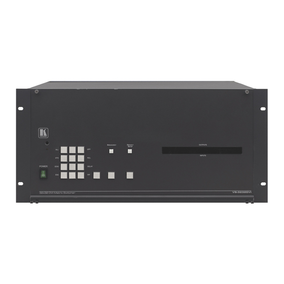
Page 8: Figure 1: Vs-3232Dvi 32X32 Dvi Matrix Switcher Front Panel
Defining the VS-3232DVI 32x32 DVI Matrix Switcher Figure 1: VS-3232DVI 32x32 DVI Matrix Switcher Front Panel Note: Buttons 12, 13 and 14 function as the TAKE, MENU and LOCK buttons respectively... -
Page 9: Figure 2: Vs-3232Dvi Numeric Keypad
Defining the VS-3232DVI 32x32 DVI Matrix Switcher Table 1: Front Panel VS-3232DVI 32x32 DVI Matrix Switcher Front Panel Features Feature Function Press to exit the current operation EDID Press to assign EDID channels Press to store the current setup in the a preset... -
Page 10: Figure 3: Vs-3232Dvi 32X32 Dvi Matrix Switcher Rear Panel
Defining the VS-3232DVI 32x32 DVI Matrix Switcher Figure 3: VS-3232DVI 32x32 DVI Matrix Switcher Rear Panel... -
Page 11: Using The Ir Transmitter
Defining the VS-3232DVI 32x32 DVI Matrix Switcher Table 3: VS-3232DVI 32x32 DVI Matrix Switcher Rear Panel Features Feature Function AC Mains Power Unit Fuse holder and power cord socket. Connect to the AC mains supply IN 1~4, 5~8, 9~12, Connect to the DVI video sources (1 to 16) (see... -
Page 12: Installing The Vs-3232Dvi In A Rack
Installing the VS-3232DVI in a Rack Installing the VS-3232DVI in a Rack This section provides instruction on rack mounting the VS-3232DVI. -
Page 13: Connecting The Vs-3232Dvi 32X32 Dvi Matrix Switcher
1. Connect up to 32 DVI video sources (for example , computer graphics sources). 1 Switch OFF the power on each device before connecting it to your VS-3232DVI 2 In this example only two inputs and two outputs are connected KRAMER: SIMPLE CREATIVE TECHNOLOGY... -
Page 14: Connecting To The Vs-3232Dvi Via Rs-232
RS-232 connection using, for example, a Kramer Tools™ VP-43xl Interface Converter. The method of connecting to the RS-232 port on the VS-3232DVI depends on the gender of the 9-pin D-sub connector on your device. Verify whether your VS-3232DVI has a male or female 9-pin D-sub connector: •... -
Page 15: Connecting To A Female 9-Pin D-Sub Connector
) for connection via a network hub or network router 6.2.1 Connecting the Ethernet Port directly to a PC You can connect the Ethernet port on the VS-3232DVI to the Ethernet port on your PC via a crossover cable with RJ-45 connectors. -
Page 16: Figure 6: Local Area Connection Properties Window
Connecting the VS-3232DVI 32x32 DVI Matrix Switcher Figure 6: Local Area Connection Properties Window 6. Select Use the following IP Address and enter the details as shown in Figure Figure 7: Internet Protocol (TCP/IP) Properties Window 7. Click OK. -
Page 17: Connecting To The Ethernet Port Via A Network Switch/Hub
Operating Your Video Matrix Switcher 6.2.2 Connecting to the Ethernet Port via a Network Switch/Hub To connect to the Ethernet port on the VS-3232DVI via a network switch/hub: • Connect the PC to the Ethernet network switch/hub using a straight through... -
Page 18: Viewing The Display
7.2 Using the Selector Buttons The VS-3232DVI can handle two digit numbers as well as one digit numbers (for numbers under 10). When entering a one-digit number (for example 5), you can either press 0 followed by 5, or 5 followed by ENT. -
Page 19: Toggling Between The At Once And Confirm Modes
To switch one input to one output: 1. Using the numeric keypad, enter the required output (in this example, 26). The following is displayed: 1 Failure to press the TAKE button within half minute (the timeout) will abort the action KRAMER: SIMPLE CREATIVE TECHNOLOGY... -
Page 20: Switching Several Inputs To Several Outputs
Operating Your Video Matrix Switcher 22 23 24 25 26 27 28 29 00 00 00 00 00 00 00 00 In__ => Out 26 The left-hand side of the display shows a section of the output/input display, automatically sliding the content to include output 26. 2. -
Page 21: Turning Off Several Outputs
• Press and hold LOCK until the button lights. To unlock the front panel buttons, press and hold LOCK until the button is no longer lit. 1 You can still remotely operate via RS-232 or Ethernet even when the front panel is locked KRAMER: SIMPLE CREATIVE TECHNOLOGY... -
Page 22: Using The Configuration Menus
Using the Configuration Menus Using the Configuration Menus The configuration menus let you configure the VS-3232DVI to best suit your needs. There are two configuration menus: • Setup Menu—those that are accessed on a regular basis (for example, storing setups and setting the delay), see Section 8.1... -
Page 23: Setup Menu-3: Outxx=>Off, Turning An Output Off
Each input on the VS-3232DVI has a factory default EDID loaded (see Section 13). The EDID for each input can be changed independently by uploading an EDID binary file to each input via the RS-232 port using Kramer EDID Sender software To assign an EDID to an input: 1. -
Page 24: Setup Menu-9: Delay, Setting For An Output
Using the Configuration Menus 5. Press TAKE. The EDID is stored and passed through to the output. The display reverts to the output/input display. To view the EDID assignments: 1. Press MENU. The Setup Menu options are displayed. 2. Press 7 (EDID). The following is displayed: SETUP EDID ENTER to View EDID and Set EDID... -
Page 25: Setup Menu-6: Recall Setup Xx, Recalling A Preset
Wait ….. After a few seconds, the following is displayed on the right hand side: CONFIRM RECALL <= 02 The TAKE button flashes. 4. Press TAKE. The preset is recalled. The display reverts to the output/input display. KRAMER: SIMPLE CREATIVE TECHNOLOGY... -
Page 26: Using The Config Menu
• Protocol configuration ( Section 8.2.5 • Storing the default setup ( Section 8.2.6 • Resetting the VS-3232DVI ( Section 8.2.7 • Firmware revision display ( Section 8.2.8 To enter the Config Menu press MENU twice. The MENU button lights and the... -
Page 27: Config Menu-Output Load Detection Display
To activate or deactivate the IR or Ethernet interfaces: 1. Press MENU twice. The following message is displayed: start configuration menu MENU to view setup ENT to change them 2. Press MENU until the following is displayed: INTERFACE configuration current:IR-ON Ethernet-ON KRAMER: SIMPLE CREATIVE TECHNOLOGY... -
Page 28: Config Menu-Interface Reply Configuration
After a few seconds the next option on the Config Menu is displayed. 8.2.5 Config Menu—Protocol Configuration This option is for future use. At the time of printing the VS-3232DVI only supports Kramer Protocol 2000. 8.2.6 Config Menu—Store Default Setup This option lets you store the current setup as the default setup. -
Page 29: Config Menu-Total Matrix Reset
4. Press 1 to turn off all outputs or 2 to perform a factory reset of all options. Caution: Selecting option 2 to perform a factory default reset clears all setups, options and configuration. 5. Press TAKE and wait a few seconds. The following is displayed: KRAMER: SIMPLE CREATIVE TECHNOLOGY... -
Page 30: Config Menu-Display Firmware Versions
Configuring the Number of Installed Input and Output Ports Are you Absolutely sure !!! Once more TAKE to confirm 6. Press TAKE. The following is displayed: Matrix erased!!! Please, wait … The matrix is erased. After a few seconds the next option on the Config Menu is displayed. -
Page 31: Installing And Using The Test Module To Troubleshoot Video Problems
10 Installing and Using the Test Module to Troubleshoot Video Problems The VS-3232DVI includes a test module which can act as a video signal generator and can be used to diagnose video issues in an operating environment. The test module must be installed in the configuration before it can be used. When... -
Page 32: Setting The Pattern Of The Generated Video
The test module may be used in a number of ways to isolate video problems. The following examples are based on the signal paths shown in Figure 10 and a VS-3232DVI device configured as follows: • 32 inputs and 32 outputs • The test module is installed and configured (see Section 10.1 •... -
Page 33: Testing The Projector Output
6. Set the pattern for the generated video (see Section 10.3 7. Verify that the projector output is as expected. 11 Upgrading the VS-3232DVI Firmware Upgrading the firmware on the VS-3232DVI can only be done by authorized service personnel. KRAMER: SIMPLE CREATIVE TECHNOLOGY... -
Page 34: Technical Specifications
Technical Specifications 12 Technical Specifications Table 5 lists the technical specifications. Table 5: Technical Specifications of the 32x32 DVI Matrix Switcher INPUTS: 32 DVI, 1.2Vpp on DVI Molex 24-pin (F) connectors; DDC signal 5Vpp (TTL) OUTPUTS: 32 DVI, 1.2Vpp on DVI Molex 24-pin (F) connectors; DDC signal 5Vpp (TTL) BANDWIDTH: Supports up to 1.65Gbps bandwidth per graphic channel COMPLIANCE WITH STANDARDS:... - Page 35 1600 x 1200p at 60Hz - VESA STD Report information Date generated... 12-Dec-10 Software revision..2.53.0.861 Data source....File Operating system..5.1.2600.2.Service Pack 3 Raw data 00,FF,FF,FF,FF,FF,FF,00,2E,4D,00,02,01,00,00,00,0C,10,01,03,81,46,27,78,0A,D5,7C,A3,57,49,9C,25,11,48,4B,FF,FF,80,8B,C0,81,0 0,95,00,81,40,81,80,90,40,B3,00,A9,40,0E,1F,00,80,51,00,1E,30,40,80, 37,00,6F,13,11,00,00,1E,28,3C,80,A0, 70,B0,23,40, 30,20, 36, 00,06,44,21,00,00,1A,00,00,00,FC,00,56, 53,2D,33,32,44,56,49,53,0A,20,20,20,00,00, 00,FD,00,32,55,1F,5E,11,00,0A, 20,20,20, 20, 20,20,00,39 KRAMER: SIMPLE CREATIVE TECHNOLOGY...
-
Page 36: Communication Protocols
Communication Protocols 14 Communication Protocols Tables of HEX Codes for Serial Communication (Protocol 2000) Table 6 lists the Protocol 2000 hex codes for switching inputs 1 to 32 to outputs 1 to 16. The communication parameters are 9600 baud, no parity, 8 data bits and 1 stop bit. - Page 37 Communication Protocols KRAMER: SIMPLE CREATIVE TECHNOLOGY...
-
Page 38: Table 7: Hex Table (In 1-32 To Out 17-32)
Communication Protocols T able 7 l ists the hex codes for switching inputs 1 to 32 to outputs 17 to 32. Table 7: Hex Table (IN 1-32 to OUT 17-32) - Page 39 Communication Protocols KRAMER: SIMPLE CREATIVE TECHNOLOGY...
- Page 40 Communication Protocols...
- Page 41 Communication Protocols KRAMER: SIMPLE CREATIVE TECHNOLOGY...
- Page 42 EXCLUSION OF DAMAGES The liability of Kramer for any effective products is limited to the repair or replacement of the product at our option. Kramer shall not be liable for: 1. Damage to other property caused by defects in this product, damages based upon inconvenience, loss of use of the product, loss of time, commercial loss;...
- Page 43 For the latest information on our products and a list of Kramer distributors visit www.kramerelectronics.com where updates to this user manual may be found. We welcome your questions, comments and feedback. Safety Warning: Disconnect the unit from the power supply before opening/servicing.
Need help?
Do you have a question about the VS-3232DVI and is the answer not in the manual?
Questions and answers