Table of Contents
Advertisement
Quick Links
Download this manual
See also:
User Manual
Advertisement
Table of Contents

Related Manuals for Kramer VS-3232A


Summary of Contents for Kramer VS-3232A
- Page 1 Kramer Electronics, Ltd. USER MANUAL Model: VS-3232A 32x32 Audio Matrix Switcher...
-
Page 2: Table Of Contents
The Follow-System versus the Master/Slave Configuration Setups Assembling a Multi-channel Audio Switcher Connecting the VS-3232A as a Companion to the VS-3232V(xl) Connecting the VS-3232A as a Companion to a Multi-channel Video Switcher 19 DIP-switch Settings 7.5.1 Setting the Machine # Connecting a Control Interface 7.6.1... - Page 3 Figure 3: Rear Panel VS-3232A 32x32 Audio Matrix Switcher Figure 4: Connecting the VS-3232A Audio Matrix Switcher Figure 5: Connecting a Balanced VS-3232A Stereo Audio Input and Output Figure 6: Connecting an Unbalanced VS-3232A Stereo Audio Input Figure 7: Connecting an Unbalanced VS-3232A Stereo Audio Output...
- Page 4 Figure 11: Configuring a 4-channel 32x32 Switcher with Two VS-3232A Switchers Figure 12: Connecting the VS-3232A as a Companion to the VS-3232Vxl Figure 13: Connecting the VS-3232A as a Companion to a Multi-channel Switcher Figure 14: DIP-switches Figure 15: Connecting a PC to two VS-3232A Units...
-
Page 5: Introduction
Scan Converters and Scalers; GROUP 8: Cables and Connectors; GROUP 9: Room Connectivity; GROUP 10: Accessories and Rack Adapters; GROUP 11: Sierra Products 2 Download up-to-date Kramer user manuals from our Web site at http://www.kramerelectronics.com 3 The complete list of Kramer cables is on our Web site at http://www.kramerelectronics.com... - Page 6 Getting Started KRAMER: SIMPLE CREATIVE TECHNOLOGY...
-
Page 7: Overview
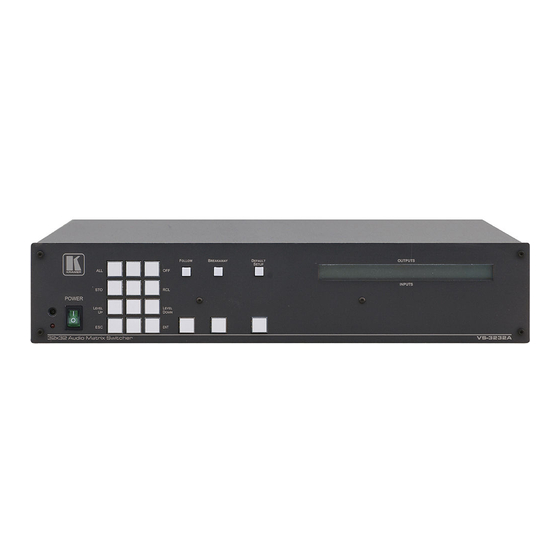
Avoid interference from neighboring electrical appliances that may adversely influence signal quality and position your VS-3232A away from moisture, excessive sunlight and dust Your Balanced Stereo Audio Matrix Switcher Figure 1 and Table 1 define the front panel of the VS-3232A. -
Page 8: Figure 1: Front Panel Vs-3232A 32X32 Audio Matrix Switcher
Your Balanced Stereo Audio Matrix Switcher LOCK TAKE MENU Figure 1: Front Panel VS-3232A 32x32 Audio Matrix Switcher KRAMER: SIMPLE CREATIVE TECHNOLOGY... -
Page 9: Table 1: Front Panel Vs-3232A 32X32 Audio Matrix Switcher Features
Table 1: Front Panel VS-3232A 32x32 Audio Matrix Switcher Features Feature Function IR Receiver The red LED is illuminated when receiving signals from the Kramer infrared remote control transmitter POWER Switch Illuminated switch for turning the unit ON or OFF... -
Page 10: Figure 2: Vs-3232A Keypad Selector Buttons
Press to enter the options in a setup menu Figure 3 and Table 3 define the rear panel of the VS-3232A. 1 See section 8.4 2 This button is enabled and illuminated after pressing the MENU button... -
Page 11: Figure 3: Rear Panel Vs-3232A 32X32 Audio Matrix Switcher
Your Balanced Stereo Audio Matrix Switcher Figure 3: Rear Panel VS-3232A 32x32 Audio Matrix Switcher... -
Page 12: Using The Ir Transmitter
Your Balanced Stereo Audio Matrix Switcher Table 3: Rear Panel VS-3232A 32x32 Audio Matrix Switcher Features Feature Function INPUT Terminal Block Connect to the balanced stereo audio sources (from 1 to 32) Connectors OUTPUT Terminal Block Connect to the balanced stereo audio acceptors (from 1 to 32) -
Page 13: Installing The Vs-3232A In A Rack
Installing the VS-3232A in a Rack Installing the VS-3232A in a Rack This section describes what to do before installing on a rack and how to rack mount. Before Installing in a rack How to Rack Mount Before installing in a rack, be sure that the environment is... -
Page 14: Connecting A Single Vs-3232A 32X32 Audio Matrix Switcher
Connecting a Single VS-3232A 32x32 Audio Matrix Switcher Connecting a Single VS-3232A 32x32 Audio Matrix Switcher To connect the VS-3232A as illustrated in the example in Figure 4, do the following 1. Connect up to 32 balanced audio sources 2. Connect up to 32 balanced audio acceptors 3. -
Page 15: Connecting The Balanced/Unbalanced Stereo Audio Input/Output
An unbalanced stereo audio input, see Figure 6 An unbalanced Stereo Audio Output, see Figure 7 L+ L- Figure 5: Connecting a Balanced VS-3232A Stereo Audio Input and Output Figure 6: Connecting an Unbalanced VS-3232A Stereo Audio Input Figure 7: Connecting an Unbalanced VS-3232A Stereo Audio Output... -
Page 16: Vs-3232A 32X32 Audio Matrix Switcher Configurations
VS-3232A 32x32 Audio Matrix Switcher Configurations VS-3232A 32x32 Audio Matrix Switcher Configurations The VS-3232A belongs to a series of 32x32 matrix switchers, including the VS-3232V and the VS-3232Vxl, and as such, can interconnect with them. The following sections describe: The VS-3232A configuration setups (see section 7.1) Various matrix configurations (see sections 7.2, 7.3, and 7.4) -
Page 17: Figure 8: Connecting In The Follow-System Configuration Setup
FOLLOW state. DIP 5 defines whether the VS-3232A unit can communicate with other switchers via a common control line. Set DIP 5 to:... -
Page 18: The Master/Slave Configuration Setup
On the Slave VS-3232A unit, the LCD display , shows the following message upon initialization However, during normal operation, the display on the Slave VS-3232A unit all the changes that were made in the Master VS-3232A unit. dynamically shows The front panel control is managed via the Master unit, on which the front panel buttons are unlocked and the LCD display illuminates. -
Page 19: Figure 9: Connecting In The Master/Slave Configuration Setup
DIP 5 is set to OFF on all three switchers and DIP 6 is set to OFF on the CV VS-3232Vxl switcher (the Master) and to ON on the two VS-3232A audio switchers (the Slaves). All the units have the same machine number (see section 7.5.1). -
Page 20: The Follow-System Versus The Master/Slave Configuration Setups
DIP 5 is set to ON on all the units. DIP 6 is set to OFF on the CV VS-3232Vxl switcher and on the A1 English language VS-3232A audio switcher. DIP 6 is set to ON on the A2 French language VS-3232A audio switcher. -
Page 21: Assembling A Multi-Channel Audio Switcher
When turning the system ON, the Slave unit initialization sequence automatically follows the Master unit initialization sequence. Master Slave … … INPUTS OUTPUTS (A, B, C, D) (A, B, C, D) Figure 11: Configuring a 4-channel 32x32 Switcher with Two VS-3232A Switchers... -
Page 22: Figure 12: Connecting The Vs-3232A As A Companion To The Vs-3232Vxl
VS-3232A 32x32 Audio Matrix Switcher Configurations 7.3 Connecting the VS-3232A as a Companion to the VS-3232V(xl) You can connect the VS-3232A as an analog audio companion to the VS-3232Vxl 32x32 Video Matrix Switcher, as illustrated in the example in Figure 12. -
Page 23: Connecting The Vs-3232A As A Companion To A Multi-Channel Video Switcher
VS-3232A 32x32 Audio Matrix Switcher Configurations 7.4 Connecting the VS-3232A as a Companion to a Multi-channel Video Switcher You can connect the VS-3232A to a multi-channel system such as a switcher for YUV (RGB) by combining three VS-3232Vxl units Y/G Channel Switcher - Master (... -
Page 24: Dip-Switch Settings
Connect the communication line between the switchers via the RS-232 or RS-485 control interface as section 7.6 describes. 7.5 DIP-switch Settings By default all the DIP-switches are set to OFF. Configure the VS-3232A by setting the eight DIP-switches as Figure 14 and Table 6 define: FOLLOW-SYSTEM... -
Page 25: Setting The Machine
RS-232 control interface and not via the RS-485 control interface. You may transfer from one interface to another via the Kramer VP-43xl Interface Converter . You can choose the RS-232 control interface, if the range is less than 25 meters for each point-to-point connection. -
Page 26: Figure 15: Connecting A Pc To Two Vs-3232A Units
7.6.1.1 Connecting a PC to a VS-3232A Unit via RS-232 To connect a PC to a VS-3232A unit, using the Null-modem adapter provided with the machine (the default): 1. Connect the RS-232 IN 9-pin D-sub rear panel port on the Master... -
Page 27: Connecting The Rs-485 Control Interface
VS-3232A 32x32 Audio Matrix Switcher Configurations To connect a PC to the VS-3232A unit, without using a Null-modem adapter: 1. Connect the RS-232 9-pin D-sub port on your PC to the RS-232 IN 9-pin D-sub rear panel port on the Master VS-3232A with a 9-wire cable to the RS-232 9-pin D-sub port on your PC. -
Page 28: Figure 17: Connecting The Rs-485 Connectors Between Vs-3232A/Vs-3232V(Xl) Units
(from the series of 32x32 or 16x16 matrix switchers), as Figure 17 illustrates: 1. Connect the “ A” PIN on the first VS-3232A unit to the “ A” PIN on the VS-3232Vxl unit and to all the other video units. -
Page 29: Setting The Sync
DIP 8 ON Figure 18: RS-485 Control Interface and SYNC Connections 7.7 Setting the Sync You can set the VS-3232A to switch simultaneously with video (a sync derived from another 32x32 or 16x16 series switcher) via the RS-485 sync terminal block connector... -
Page 30: Controlling Via The Ethernet
7.8.1 Connecting the ETHERNET Port directly to a PC (Crossover Cable) You can connect the Ethernet port of the VS-3232A to the Ethernet port on your PC, via a crossover cable with RJ-45 connectors. This type of connection is recommended for identification of the factory default... -
Page 31: Connecting The Ethernet Port Via A Network Hub (Straight-Through Cable)
Figure 20: Internet Protocol (TCP/IP) Properties Window 7.8.2 Connecting the ETHERNET Port via a Network Hub (Straight-Through Cable) You can connect the Ethernet port of the VS-3232A to the Ethernet port on a network hub or network router, via a straight-through cable with RJ-45 connectors. -
Page 32: Operating Your Video Matrix Switcher
#$ % #$ &&& Figure 21: Default Startup Status Display Sequence The front panel of the VS-3232A includes a numerical keyboard within the Keypad area . This keypad includes the numbers from 0 to 9 and lets you enter both the output and input numbers. -
Page 33: Viewing The Display
8.2 Using the Keypad Buttons Since the VS-3232A has 32 inputs and outputs (and up to 59 setups that can be recalled), it can handle two digit numbers as well as one digit numbers (for numbers under 10). -
Page 34: Toggling Between The At Once And Confirm Modes
Several inputs to several outputs (see section 8.4.2) One input to all outputs (see section 8.4.3) 1 Failure to press the TAKE button within half minute (the Timeout) will abort the action 2 For about 2 seconds KRAMER: SIMPLE CREATIVE TECHNOLOGY... -
Page 35: Switching One Input To One Output
Press the blinking TAKE button to switch the input to the output 8.4.2 Switching Several Inputs to Several Outputs In the At Once mode, the VS-3232A will execute each OUT-IN combination separately (see section 8.4.1). If you want to switch several inputs to several outputs simultaneously, it is necessary to operate the machine in the Confirm mode. -
Page 36: Switching One Input To All Outputs
All the outputs can be cleared only through the configuration menu (see section 9). 1 The ALL, OFF, STO and RCL buttons 2 Turning OFF the output/s, that is no input is routed to the output/s KRAMER: SIMPLE CREATIVE TECHNOLOGY... -
Page 37: Storing And Recalling Setups
Operating Your Video Matrix Switcher 8.5 Storing and Recalling Setups You can store up to 59 settings in the non-volatile memory with the ability to recall each of those settings. A stored and recalled setup includes the cross-point connections as well as the audio level for all the 32 inputs and 32 outputs. -
Page 38: Recalling Setups
1 When trying to recall a setup beyond 59, the LCD display shows the following message: 2 That is, a setup # for which no setup is actually stored 3 The same as in step 2 above KRAMER: SIMPLE CREATIVE TECHNOLOGY... -
Page 39: Choosing The Follow Or The Breakaway Modes
The VS-3232A unit will function in the FOLLOW-System mode if at least one other VS-3232A unit is set to the FOLLOW-System mode and these units interconnect via an RS-232 and/or RS-485 communication line. To set the VS-3232A unit to function in the FOLLOW-System mode: 1. - Page 40 The FOLLOW stops blinking and then illuminates, the BREAKAWAY button no longer illuminates and the LCD display restores its last content. If the cross-points status of the VS-3232A is different from the other online switchers in the FOLLOW-System mode, the FOLLOW button stops blinking...
-
Page 41: Using The Lock Button
2 seconds. The LOCK button illuminates when in the Lock state. 8.9 Setting the Input/Output Volume The volume of each input and output on the VS-3232A can be controlled individually. The volume level of the left and right channels for each input/output can be set separately or together using the LEVEL UP and LEVEL DOWN front panel buttons. - Page 42 9. Upon completion of the adjustment, the LCD displays the following: " " If you want to adjust other input or output channels, press ENT. Do the same to adjust any of the output levels (from 0dB to -100dB). KRAMER: SIMPLE CREATIVE TECHNOLOGY...
-
Page 43: The Menu Commands
The MENU Commands The MENU Commands The menu lets you configure the VS-3232A to best suit your needs. To enter the configuration menu, press the menu button three times. The MENU button illuminates. And the following message appears on the LCD... -
Page 44: Figure 22: Setting The Sync Configuration (An Example)
Interface REPLY configuration (see section 9.4) PROTOCOL configuration (see section 9.5) Store DEFAULT setup (see section 9.6) Set the initializing sequence delay time (see section 9.7) Indication of the current Firmware version (see section 9.8) TOTAL RESET options (see section 9.9) KRAMER: SIMPLE CREATIVE TECHNOLOGY... -
Page 45: Selecting The Audio Switching Method
The MENU Commands 9.1 Selecting the Audio Switching Method Table 8 summarizes the audio switching method configuration options: Table 8: Audio Switching Method Configuration Menu Press: To select: After the change, the LCD displays: FADE Out-In (Clean switching) Audio Switching set to FADE Out-In (Clean switching) (this mode is preferred for a standalone unit). -
Page 46: Selecting The Interface Reply Configuration
Table 12: PROTOCOL Configuration Menu Press: To select: After the change, the LCD displays: HEXadecimal, for setting the protocol Communication protocol set to HEX KRAMER-2000 HEX KRAMER-2000 ASCII, for setting the protocol to ASCII – Communication protocol set to ASCII – SIERRA SIERRA 9.6 Selecting the Store DEFAULT Setup Configuration... -
Page 47: Selecting The Initialization Sequence Delay Time For A Slave Unit
The MENU Commands 9.7 Selecting the Initialization Sequence Delay Time for a Slave Unit When several VS-3232A units are used together, it is necessary to set up the delay time of each slave unit. To configure the Initialization sequence delay time 1. -
Page 48: Selecting The Total Reset Option
The SYNC configuration is set to GENLOCK OFF- immediate switching All the interfaces are set to ON The interface Reply is set to Reply The interface protocol is set to Hex Kramer 2000 The default setup is set to the Factory default KRAMER: SIMPLE CREATIVE TECHNOLOGY... -
Page 49: Flash Memory Upgrade
3. Create a shortcut on your desktop to the file: “ FLIP.EXE” . 10.1.2 Connecting the PC to the RS-232 Port Before installing the latest Kramer firmware version on a VS-3232A unit, do the following: 1. Turn the unit OFF. -
Page 50: Upgrading Firmware
3. Press the keyboard shortcut key F2 (or select the “ Select” command from the Device menu, or press the integrated circuit icon in the upper right corner of the window). The “ Device Selection” window appears: KRAMER: SIMPLE CREATIVE TECHNOLOGY... -
Page 51: Figure 25: Device Selection Window
Flash Memory Upgrade Figure 25: Device Selection Window 4. Click the button next to the name of the device and select from the list: AT89C51ED2: AT89C51ED2 T89C51RD2 Figure 26: Device Selection window 5. Click OK and select “ Load Hex” from the File menu. -
Page 52: Figure 27: Loading The Hex
Figure 27: Loading the Hex 6. The Open File window opens. Select the correct HEX file that contains the updated version of the firmware for VS-3232A (for example 32M_V1p2.hex) and click Open. 7. Press the keyboard shortcut key F3 (or select the “ Communication / RS232”... - Page 53 Flash Memory Upgrade Verify that in the Buffer Information column, the “ HEX File: VS3232A.hex” appears. VS32 32 A.h ex Figure 29: Atmel – Flip Window (Connected) 9. Click Run. After each stage of the operation is completed, the check-box for that stage becomes colored green When the operation is completed, all 4 check-boxes will be colored green and the status bar message: Memory Verify Pass appears...
-
Page 54: Ethernet Flash Memory Upgrade
Before installing the latest Kramer Ethernet firmware version on the VS-3232A, do the following: 1. Connect the RS-232 IN 9-pin D-sub port (COM 1) on the VS-3232A to a Null-modem adapter and connect the Null-modem adapter with a 9-wire flat cable to the RS-232 9-pin D-sub COM port on your PC. -
Page 55: Upgrading Firmware
5. Wait until downloading is completed and the red Send button turns off. 6. Disconnect the power on the VS-3232A. 7. Release the ETHERNET FLASH button on the rear panel. 8. Connect the power on your machine. 1 To which the VS-3232A is connected on your PC... -
Page 56: Technical Specifications
Technical Specifications 11 Technical Specifications Table 15 includes the technical specifications: Table 15: Technical Specifications of the VS-3232A Video Matrix Switcher INPUTS: 32 balanced stereo inputs on 5-pin detachable terminal block connectors OUTPUTS: 32 balanced stereo outputs on 5-pin detachable terminal block connectors INPUT IMPEDANCE: >10k (AC coupled) -
Page 57: Audio Performance Graphs
This section describes the audio performance of the left and right signals 1,2,3 output from the VS-3232A Figure 32: Frequency Response (Bandwidth) of the VS-3232A Figure 33: THD+N of the VS-3232A Output Level Figure 34: Maximum Input/Output Level at 1kHz... -
Page 58: Communication Protocols
Figure 36: Spectrum Plot of the Output Signal for a 1kHz, 4dBu Input 12 Communication Protocols Using the menu, you can select the: Kramer 2000 communication protocol (see section 12.1), or ASCII Protocol (see section 12.2) 12.1 The Kramer 2000 Communication Protocol... -
Page 59: Table 16: Hex Table (In 1-32 To Out 1-16)
Communication Protocols Table 16: Hex Table (IN 1-32 to OUT 1-16) - Page 60 Communication Protocols KRAMER: SIMPLE CREATIVE TECHNOLOGY...
-
Page 61: Table 17: Hex Table (In 1-32 To Out 17-32)
Communication Protocols Table 17: Hex Table (IN 1-32 to OUT 17-32) - Page 62 Communication Protocols KRAMER: SIMPLE CREATIVE TECHNOLOGY...
-
Page 63: Ascii Protocol: General
ASCII even after cycling power. To check that the protocol has been selected, and to confirm that the communication is OK, send the string **!! to the VS-3232A. It should reply by sending the string OK!! 12.2.1 ASCII Protocol: Description... - Page 64 EXCLUSION OF DAMAGES The liability of Kramer for any effective products is limited to the repair or replacement of the product at our option. Kramer shall not be liable for: 1. Damage to other property caused by defects in this product, damages based upon inconvenience, loss of use of the product, loss of time, commercial loss;...
- Page 65 For the latest information on our products and a list of Kramer distributors, visit our Web site: www.kramerelectronics.com, where updates to this user manual may be found. We welcome your questions, comments and feedback. Safety Warning: Disconnect the unit from the power supply before opening/servicing.
Need help?
Do you have a question about the VS-3232A and is the answer not in the manual?
Questions and answers