Table of Contents
Advertisement
Quick Links
Advertisement
Table of Contents

Subscribe to Our Youtube Channel
Related Manuals for Kramer VS-3232V


Summary of Contents for Kramer VS-3232V
- Page 1 Kramer Electronics, Ltd. USER MANUAL Model: VS-3232V 32x32 Video Matrix Switcher...
-
Page 2: Table Of Contents
Quick Start Overview Your Video Matrix Switcher Installing the VS-3232V on a Rack Connecting the Video Matrix Switcher Connecting the VS-3232V as a Composite Video Switcher Assembling a Multi-channel Video Switcher 6.2.1 Configuring a 32x32 Y/C Switcher (Two Units) 6.2.2 Configuring a 32x32 YUV/RGB Switcher (Three Units) 6.2.3... - Page 3 Figure 3: Configuring the VS-3232V for Composite Video Figure 4: Configuring a 32x32 s-Video (YC) Switcher with two VS-3232V Switchers Figure 5: Configuring a 32x32 YUV (RGB) Switcher with three VS-3232V Switchers 14 Figure 6: Dipswitches Figure 7: Connecting a PC to Three VS-3232V Units...
- Page 4 Figure 22: Atmel – Flip Window (Operation Completed) Figure 23: The KFR-Programmer Window Tables Table 1: Front Panel VS-3232V 32x32 Video Matrix Switcher Features Table 2: Rear Panel VS-3232V 32x32 Video Matrix Switcher Features Table 3: Dipswitch Definitions Table 4: Machine # Dipswitch Settings...
-
Page 5: Introduction
GROUP 6: Accessories and Rack Adapters; GROUP 7: Scan Converters and Scalers; and GROUP 8: Cables and Connectors 2 Downloadable from our Web site at http://www.kramerelectronics.com 3 Download up-to-date Kramer user manuals from our Web site: http://www.kramerelectronics.com 4 The complete list of Kramer cables is on our Web site at http://www.kramerelectronics.com... - Page 6 Getting Started KRAMER: SIMPLE CREATIVE TECHNOLOGY...
-
Page 7: Overview
Three SYNC switching options make the VS-3232V appropriate for a wide range of glitch-free transition applications. The VS-3232V can be used as a standalone unit, or configured as a part of a multi-signal Kramer switcher system, in which all units switch simultaneously. -
Page 8: Your Video Matrix Switcher
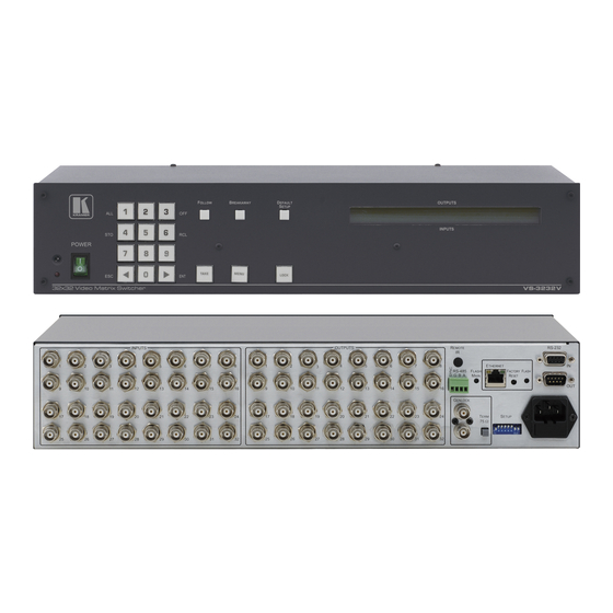
Your Video Matrix Switcher Figure 1 and Figure 2 illustrate the front and rear panels of the VS-3232V, respectively. Table 1 and Table 2 define the front and rear panels of the VS-3232V, respectively. -
Page 9: Figure 1: Vs-3232V 32X32 Video Matrix Switcher Front Panel
Your Video Matrix Switcher TAKE MENU LOCK Figure 1: VS-3232V 32x32 Video Matrix Switcher Front Panel... -
Page 10: Table 1: Front Panel Vs-3232V 32X32 Video Matrix Switcher Features
Power Switch Illuminated switch for turning the unit ON or OFF IR Receiver The red LED is illuminated when receiving signals from the Kramer Infra- red remote control transmitter 1 This button is enabled and illuminated after pressing the MENU button... -
Page 11: Figure 2: Vs-3232V 32X32 Video Matrix Switcher Rear Panel
Your Video Matrix Switcher Figure 2: VS-3232V 32x32 Video Matrix Switcher Rear Panel... -
Page 12: Table 2: Rear Panel Vs-3232V 32X32 Video Matrix Switcher Features
For GENLOCK SYNC input/loop Connectors 1 Optional. Can be used instead of the front panel (built-in) IR receiver to remotely control the VS-3232V (only if the internal IR connection cable has been installed) 2 Using a small screwdriver if required 3 Turn the machine OFF using the power switch and then turn it ON while pressing the ETH Factory Reset button. -
Page 13: Installing The Vs-3232V On A Rack
The machine is earthed (grounded) in a reliable way and is connected only to an electricity socket with If you are using a Kramer rack adapter grounding. Pay particular attention to situations where kit (for a machine that is not 19"), see... -
Page 14: Connecting The Video Matrix Switcher
SYNC (see section 6.2.3) 6.1 Connecting the VS-3232V as a Composite Video Switcher To install the VS-3232V as illustrated in the example in Figure 3, do the following 1. Connect up to 32 composite video sources (for example , two composite video players). -
Page 15: Figure 3: Configuring The Vs-3232V For Composite Video
Connecting the Video Matrix Switcher Figure 3: Configuring the VS-3232V for Composite Video... -
Page 16: Assembling A Multi-Channel Video Switcher
Connecting the Video Matrix Switcher 6.2 Assembling a Multi-channel Video Switcher You can configure several VS-3232V units as 32x32 multi-channel video switchers for: s-Video (Y/C) by combining two VS-3232V units (see section 6.2.1) YUV (RGB) by combining three VS-3232V units (see section 6.2.2) RGBS by combining four VS-3232V units (see section 6.2.3) -
Page 17: Configuring A 32X32 Y/C Switcher (Two Units)
Display s-Video Player Figure 4: Configuring a 32x32 s-Video (YC) Switcher with two VS-3232V Switchers 1 The INPUT 1 connectors on the Y switcher and the C switcher 2 The OUTPUT 32 connectors on the Y switcher and the C switcher... -
Page 18: Configuring A 32X32 Yuv/Rgb Switcher (Three Units)
Figure 5: Configuring a 32x32 YUV (RGB) Switcher with three VS-3232V Switchers 1 For a description of how to connect the RS-485 connectors between the VS-3232V switchers, refer to section 6.4.2 2 The INPUT 1 connectors on the Y switcher, the U switcher and the V switcher... -
Page 19: Configuring A 32X32 Rgbs Switcher (Four Units)
, in a similar way to how Figure 5 in section 6.2.2 illustrates combining three VS-3232V switchers for YUV (RGB). 6.3 Dipswitch Settings Configure the VS-3232V by setting the eight dipswitches as Figure 6 and Table 3 define: SYSTEM MODE SLAVE MODE... -
Page 20: Setting The Machine
DIP 5 defines whether the VS-3232V unit can communicate with other switchers via a common control line. You can set DIP 5 OFF to disable the FOLLOW-SYSTEM mode when... -
Page 21: Understanding The Slave Mode
Slaves. The Slaves always follow the Master. In the example illustrated in Figure 5, the first VS-3232V unit is the Master (with DIP 6 set OFF enabling the Master mode) and the second and third VS-3232V units are Slaves (with DIP 6 set ON enabling the Slave mode). -
Page 22: The System Mode Versus The Master/Slave Mode
RS-232 control interface and not via the RS-485 control interface. You may transfer from one interface to another via the Kramer VP-43xl Interface Converter You can choose the RS-232 control interface, if the range is < 25 meters for each point-to-point connection. -
Page 23: Connecting The Rs-232 Control Interface
Set DIP 7 OFF Without a Null-modem adapter Set DIP 7 ON Figure 7: Connecting a PC to Three VS-3232V Units You can connect any of the following: The PC’s DB9 COM port to a VS-3232V unit (see section 6.4.1.1) Two VS-3232V units , (see section 6.4.1.2) - Page 24 To connect a PC to a VS-3232V unit, using the Null-modem adapter provided with the machine (the default): 1. Connect the RS-232 IN DB9F rear panel port on the Master VS-3232V unit to the Null-modem adapter and connect the Null-modem adapter with a 9-wire flat cable to the RS-232 DB9 port on your PC.
-
Page 25: Connecting The Rs-485 Control Interface
(from the series of 32x32 or 16x16 matrix switchers), as Figure 9 illustrates: 1. Connect the “A” PIN on the first VS-3232V unit to the “A” PIN on the second VS-3232V unit and all the other units. -
Page 26: Figure 9: Connecting The Rs-485 Connectors Between Two Vs-3232V Units
Figure 10 illustrates the RS-485 line that connects: Between each VS-3232V unit To the PC via a Kramer Tools VP-43xl Interface Converter (connect the PC’s DB 9 COM port to the RS-232 IN DB9F port on the VP-43xl. Next, connect the RS-485 port on the VP-43xl to the RS-485 ports on the... -
Page 27: Figure 10: Rs-485 Control Interface And Sync Connections For Component Switcher
Connecting the Video Matrix Switcher EXT SYNC MACHINE # 1 DIP 8 OFF 32x32 Component Video Switcher MACHINE # 1 (Three VS-3232V Units) DIP 8 OFF MACHINE # 1 DIP 8 ON Figure 10: RS-485 Control Interface and SYNC Connections for Component Switcher... -
Page 28: Configuring The Sync
Connecting the Video Matrix Switcher 6.5 Configuring the Sync You can configure the method of the switching between the video sources in the VS-3232V. The switching (transition) is done according to the selection of the SYNC input: An EXTERNAL Sync (the GENLOCK BNC connector) -
Page 29: Controlling Via The Ethernet
6.6.1 Connecting the ETHERNET Port directly to a PC (Crossover Cable) You can connect the Ethernet port of the VS-3232V to the Ethernet port on your PC, via a crossover cable with RJ-45 connectors. This type of connection is recommended for identification of the factory default... -
Page 30: Connecting The Ethernet Port Via A Network Hub (Straight-Through Cable)
6.6.2 Connecting the ETHERNET Port via a Network Hub (Straight- Through Cable) You can connect the Ethernet port of the VS-3232V to the Ethernet port on a network hub or network router, via a straight-through cable with RJ-45 connectors. 6.6.3... -
Page 31: Operating Your Video Matrix Switcher
'" (" Figure 13: Default Startup Status Display Sequence The VS-3232V does not have separate output and input pushbuttons. Instead, the front panel includes a numerical keyboard within the Selector Buttons area . This keyboard that includes the numbers from 0 to 9, lets you enter both the output and input numbers. -
Page 32: Viewing The Display
7.2 Using the Selector Buttons Since the VS-3232V has 32 inputs and outputs (and up to 59 setups that can be recalled), it can handle two digit numbers as well as one digit numbers (for numbers under 10). -
Page 33: Toggling Between The At Once And Confirm Modes
Operating Your Video Matrix Switcher In the Confirm mode (the TAKE button illuminates): You can key-in an action and then confirm it by pressing the TAKE button Every action requires user confirmation, protecting against erroneous switching Execution is delayed until the user confirms the action 7.3.1 Toggling between the At Once and Confirm Modes To toggle between the At Once and Confirm modes, do the following:... -
Page 34: Switching One Input To One Output
7.4.2 Switching several Inputs to several Outputs In the At Once mode, the VS-3232V will execute each OUT-IN combination separately (see section 7.4.1). If you want to switch several inputs to several outputs it is necessary to operate the machine in the Confirm mode. -
Page 35: Switching One Input To All Outputs
Operating Your Video Matrix Switcher 7.4.3 Switching one Input to all Outputs To switch one input to all the outputs (in the At Once mode): 1. Press the MENU button once. The Menu buttons illuminate and are enabled. 2. Press the illuminated ALL button. The LCD display shows the message: // 01 3. -
Page 36: Storing And Recalling Setups
1 In the confirm mode, the TAKE blinks and you have to press the TAKE button to confirm the operation 2 When trying to recall a setup beyond 59, the LCD display shows the following message: KRAMER: SIMPLE CREATIVE TECHNOLOGY... -
Page 37: Using The Default Setup Button (Unity Setting)
Operating Your Video Matrix Switcher When in the CONFIRM mode (the TAKE button is illuminated), repeat the steps above and then press the TAKE button to confirm the action. After recalling a setup in the CONFIRM mode, while the TAKE button is blinking, you can review the content of the recalled setup using the or the buttons. -
Page 38: Choosing The Follow Or The Breakaway Modes
The VS-3232V unit will function in the FOLLOW-System mode if at least one other VS-3232V unit is set to the FOLLOW-System mode and these units interconnect via an RS-232 and/or RS-485 communication line. To set the VS-3232V unit to function in the FOLLOW-System mode: 1. -
Page 39: Using The Lock Button
Operating Your Video Matrix Switcher If the cross-points status of the VS-3232V is different from the other online switchers in the FOLLOW-System mode, the FOLLOW button stops blinking and the TAKE button blinks, and the LCD display shows the following message: 3. -
Page 40: The Menu Commands
The MENU Commands The MENU Commands The menu lets you configure the VS-3232V to best suit your needs. To enter the configuration menu, press the menu button twice. The MENU button illuminates. And the following message appears on the LCD display: >... -
Page 41: Figure 14: Setting The Sync Configuration (An Example)
The MENU Commands MENU > TAKE MENU MENU < < @ =A TAKE MENU 3( "? @ =A )? @ = < TAKE MENU > < MENU TAKE Button blinks TAKE < TAKE MENU To the next menu item MENU )-*= TAKE MENU... -
Page 42: Selecting The Sync Configuration
After the change, the LCD displays: RS485 Interface RS-485 now active or, interface RS-485 now off IRremote IR remote now active or, IR remote now off Ethernet Network connection now active or network connection now off KRAMER: SIMPLE CREATIVE TECHNOLOGY... -
Page 43: Selecting The Interface Reply Configuration
Table 9: PROTOCOL Configuration Menu Press: To select: After the change, the LCD displays: HEXadecimal, for setting the protocol Communication protocol set to HEX KRAMER-2000 HEX KRAMER-2000 ASCII, for setting the protocol to ASCII – Communication protocol set to ASCII – SIERRA SIERRA 8.5 Selecting the DEFAULT Setup Configuration... -
Page 44: The Main Firmware Version
The SYNC is extracted from the BNC-Genlock Input All the interfaces are set to ON The interface Reply is set to Reply The interface protocol is set to Hex Kramer-2000 The DEFAULT SETUP is set to Matrix setup and cross-points KRAMER: SIMPLE CREATIVE TECHNOLOGY... -
Page 45: Flash Memory Upgrade
3. Create a shortcut on your desktop to the file: “FLIP.EXE”. 9.1.2 Connecting the PC to the RS-232 Port Before installing the latest Kramer firmware version on a VS-3232V unit, do the following: 1. Turn the unit OFF. 2. Connect the RS-232 DB9 rear panel port according to section 6.4.1. -
Page 46: Upgrading Firmware
Figure 16: Atmel – Flip Window 3. Press the keyboard shortcut key F2 (or select the “Select” command from the Device menu, or press the integrated circuit icon in the upper right corner of the window). The “Device Selection” window appears: KRAMER: SIMPLE CREATIVE TECHNOLOGY... - Page 47 Flash Memory Upgrade Figure 17: Device Selection Window 4. Click the button next to the name of the device and select from the list: AT89C51ED2: AT89C51ED2 T89C51RD2 Figure 18: Device Selection window 5. Click OK and select “Load Hex” from the File menu.
- Page 48 Figure 19: Loading the Hex 6. The Open File window opens. Select the correct HEX file that contains the updated version of the firmware for VS-3232V (for example 32M_V1p2.hex) and click Open. 7. Press the keyboard shortcut key F3 (or select the “Communication / RS232”...
-
Page 49: Figure 21: Atmel – Flip Window (Connected)
Flash Memory Upgrade Verify that in the Buffer Information column, the “HEX File: VS3232V.hex” appears. VS3232V.hex Figure 21: Atmel – Flip Window (Connected) 9. Click Run. After each stage of the operation is completed, the check-box for that stage becomes colored green When the operation is completed, all 4 check-boxes will be colored green and the status bar message: Memory Verify Pass appears VS3232V.hex... -
Page 50: Ethernet Flash Memory Upgrade
Before installing the latest Kramer Ethernet firmware version on the VS-3232V, do the following: 1. Connect the RS-232 IN DB9 port (COM 1) on the VS-3232V to a Null- modem adapter and connect the Null-modem adapter with a 9-wire flat cable to the RS-232 DB9 COM port on your PC. -
Page 51: Upgrading Firmware
5. Wait until downloading is completed and the red Send button turns off. 6. Disconnect the power on the VS-3232V. 7. Release the ETHERNET FLASH button on the rear panel. 8. Connect the power on your machine. 1 To which the VS-3232V is connected on your PC... -
Page 52: Technical Specifications
Technical Specifications 10 Technical Specifications Table 12 includes the technical specifications: Table 12: Technical Specifications of the VS-3232V Video Matrix Switcher INPUTS: 32 composite video, 1Vpp / 75 on BNC connectors OUTPUTS: 32 composite video, 1Vpp / 75 on BNC connectors VIDEO BANDWIDTH: >300MHz, -3dB / >50MHz, 0.1dB... -
Page 53: Table 13: Hex Table (In 1-32 To Out 1-16)
Communication Protocols Table 13: Hex Table (IN 1-32 to OUT 1-16) - Page 54 Communication Protocols KRAMER: SIMPLE CREATIVE TECHNOLOGY...
-
Page 55: Table 14: Hex Table (In 1-32 To Out 17-32)
Communication Protocols Table 14: Hex Table (IN 1-32 to OUT 17-32) - Page 56 Communication Protocols KRAMER: SIMPLE CREATIVE TECHNOLOGY...
-
Page 57: Ascii Protocol: General
ASCII even after cycling power. To check that the protocol has been selected, and to confirm that the communication is OK, send the string **!! to the VS-3232V. It should reply by sending the string OK!! 11.2.1... - Page 58 EXCLUSION OF DAMAGES The liability of Kramer for any effective products is limited to the repair or replacement of the product at our option. Kramer shall not be liable for: 1. Damage to other property caused by defects in this product, damages based upon inconvenience, loss of use of the product, loss of time, commercial loss;...
- Page 59 For the latest information on our products and a list of Kramer distributors, visit our Web site: www.kramerelectronics.com, where updates to this user manual may be found. We welcome your questions, comments and feedback. Safety Warning: Disconnect the unit from the power supply before opening/servicing.
Need help?
Do you have a question about the VS-3232V and is the answer not in the manual?
Questions and answers