Table of Contents
Advertisement
Quick Links
Download this manual
See also:
Installation
Advertisement
Table of Contents

Subscribe to Our Youtube Channel
Related Manuals for Kramer VS-3232DN


Summary of Contents for Kramer VS-3232DN
- Page 1 USER MANUAL MODEL: VS-3232DN 4x4 to 32x32 Modular Multi-Format Digital Matrix Switcher P/N: 2900-300164 Rev 5 www.KramerAV.com...
-
Page 6: Table Of Contents
Safety Instructions (Laser) Recycling Kramer Products About Fast Switching About HDBaseT™ Technology About EDID Overview Defining the VS-3232DN 4x4 to 32x32 Modular Multi-Format Digital Matrix Switcher Using the IR Transmitter Installing in a Rack Connecting the VS-3232DN Port Numbering Connecting to the VS-3232DN via RS-232... - Page 7 Protocol 2000 Figures Figure 1: VS-3232DN Front Panel Figure 2: VS-3232DN Front Panel Numeric Keypad Figure 3: VS-3232DN Rear Panel Showing DVI cards Figure 4: Connecting the VS-3232DN Figure 5: Sample Port Numbering Figure 6: EDID Numbering Assignment Figure 7: Local Area Connection Properties Window...
-
Page 8: Introduction
Room Connectivity; GROUP 10: Accessories and Rack Adapters; GROUP 11: Sierra Video Products; GROUP 12: Digital Signage; GROUP 13: Audio; and GROUP 14: Collaboration. Congratulations on purchasing your Kramer VS-3232DN 4x4 to 32x32 Modular Multi-Format Digital Matrix Switcher. This product, which incorporates HDMI™ technology, is ideal for: •... - Page 9 SDIA-IN4-F32 (see Section 10.11) • VGAA-IN4-F32 / VGAA-OUT4-F32 (see Section 10.12) • AAD-IN4-F32 / AAD-OUT4-F32 (see Section 10.13) The F670-IN4/OUT4-F32 cards are fully compatible with the Kramer 670T/670R and 671T/671R HDMI/DVI transmitters and receivers for non- HDCP content. VS-3232DN – Introduction...
-
Page 10: Getting Started
This equipment is to be used only inside a building. It may only be connected to other equipment that is installed inside a building. Kramer engineers have developed special twisted pair cables to best match our digital twisted pair products; Kramer's BC-UNIKAT shielded twisted pair (U/FTP) cables. -
Page 11: Safety Instructions Ac
Kramer Electronics has made arrangements with the European Advanced Recycling Network (EARN) and will cover any costs of treatment, recycling and recovery of waste Kramer Electronics branded equipment on arrival at the EARN facility. For details of Kramer’s recycling arrangements in your particular country go to our recycling pages at www.kramerav.com/support/recycling/. -
Page 12: About Fast Switching
(that is connected to the display’s source). The EDID enables the VS-3232DN to “know” what kind of monitor is connected to the output. The EDID includes the manufacturer’s name, the product type, the timing data supported by the display, the display size, luminance data and (for digital displays only) the pixel mapping data. -
Page 13: Overview
Overview The Kramer VS-3232DN is a high performance matrix switcher chassis for AV signals. The unit is modular and populated from 4 x 4 to 32 x 32 ports in increments of four inputs and/or four outputs. The unit supports various signals, depending on the type of cards installed and includes a power supply, control module and a test module that can monitor and test any video input and output in the matrix. - Page 14 • Flexible Configuration – To disable HDCP support and convert between HDMI and DVI You can operate the VS-3232DN via the front panel buttons or remotely via: • RS-232 serial commands transmitted by a touch screen system, PC or other serial controller •...
-
Page 15: Defining The Vs-3232Dn 4X4 To 32X32 Modular Multi-Format Digital Matrix Switcher
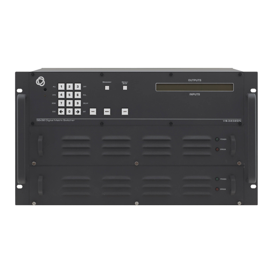
Defining the VS-3232DN 4x4 to 32x32 Modular Multi- Format Digital Matrix Switcher This section defines the front and rear panels of the VS-3232DN. Figure 1: VS-3232DN Front Panel Buttons 14, 15 and 16 function as the TAKE, MENU and LOCK buttons respectively. - Page 16 Lights green when power supply is active and the device is powered on. ERROR LED Lights red when an error is detected. Briefly lights red immediately following a power disruption (e.g., cable disconnection, power off, and so on). VS-3232DN – Overview...
-
Page 17: Figure 2: Vs-3232Dn Front Panel Numeric Keypad
Numeric keypad, 1 to 0 ► (Forward) Press to shift the display left (the LCD display only shows 13 cross-points out of a total of 32). Figure 3: VS-3232DN Rear Panel Showing DVI cards Feature Function AC Mains Power Module Fuse holder and power cord socket. -
Page 18: Using The Ir Transmitter
Connect to one of the relevant video inputs/outputs to aid in Video Connector troubleshooting (see Section Using the IR Transmitter You can use the RC-IR3 IR transmitter to control the machine via the built-in IR receiver on the front panel. VS-3232DN – Overview... -
Page 19: Installing In A Rack
Installing in a Rack This section provides instructions for rack mounting the unit (the graphics are for illustration purposes only). VS-3232DN - Installing in a Rack... -
Page 20: Connecting The Vs-3232Dn
5. If necessary, review and set the system configuration using the Menu (see Section Given an input signal that is HDCP encoded, the VS-3232DN outputs a signal only if the output port to which it is switched supports HDCP. VS-3232DN - Connecting the VS-3232DN... -
Page 21: Port Numbering
Figure 4: Connecting the VS-3232DN Port Numbering All cards (except DVI dual link cards) have four physical ports. Numbering of ports is sequential from top to bottom and left to right. Each DVI dual link card provides two physical ports which causes the loss of two numbers in the numbering sequence of that card only. -
Page 22: Figure 5: Sample Port Numbering
OUT 1, OUT 2, OUT 3, OUT 4 OUT 5, OUT 6, OUT 7, OUT 8 OUT 9, OUT 10 There is no IN 7, IN 8, OUT 11, or OUT 12 because these slots contain DVI dual link cards. VS-3232DN - Connecting the VS-3232DN... -
Page 23: Connecting To The Vs-3232Dn Via
PC. Note that a null-modem adapter/connection is not required. To connect to the VS-3232DN via RS-232: Connect the RS-232 9-pin D-sub rear panel port on the VS-3232DN unit via a • 9-wire straight cable (only pin 2 to pin 2, pin 3 to pin 3, and pin 5 to pin 5 need to be connected) to the RS-232 9-pin D-sub port on your PC. -
Page 24: Connecting To The Vs-3232Dn Via Ethernet
5.3.1 Connecting the Ethernet Port Directly to a PC You can connect the Ethernet port of the VS-3232DN directly to the Ethernet port on your PC using a crossover cable with RJ-45 connectors. This type of connection is recommended for identifying the VS-3232DN with the factory configured default IP address. -
Page 25: Figure 7: Local Area Connection Properties Window
4. Highlight either Internet Protocol Version 6 (TCP/IPv6) or Internet Protocol Version 4 (TCP/IPv4) depending on the requirements of your IT system. 5. Click Properties. The Internet Protocol Properties window relevant to your IT system appears as shown in Figure 8 Figure VS-3232DN - Connecting the VS-3232DN... -
Page 26: Figure 8: Internet Protocol Version 4 Properties Window
Figure 8: Internet Protocol Version 4 Properties Window Figure 9: Internet Protocol Version 6 Properties Window VS-3232DN - Connecting the VS-3232DN... -
Page 27: Figure 10: Internet Protocol Properties Window
5.3.2 Connecting the Ethernet Port via a Network Hub or Switch You can connect the Ethernet port of the VS-3232DN to the Ethernet port on a network hub or using a straight-through cable with RJ-45 connectors. VS-3232DN - Connecting the VS-3232DN... -
Page 28: Operating Your Video Matrix Switcher
(text in the LCD Display may vary according to machine settings). Figure 11: Default Startup Status Display Sequence The VS-3232DN does not have separate output and input buttons. Instead, the front panel includes a numeric keypad within the Selector Buttons area (see Section 3.1). -
Page 29: Using The Selector Buttons
Using the Selector Buttons For numbers between 1 and 9, the VS-3232DN can handle two digit numbers as well as single digit numbers. When entering a single digit number (for example 5), you can either press 0 followed by 5, or 5 followed by ENT. -
Page 30: Confirming Actions
1. Press TAKE to toggle between the At Once mode and the Confirm mode. The TAKE button lights and actions now require user confirmation. 2. Press the lit TAKE button to toggle from the Confirm mode back to the At Once mode. VS-3232DN - Operating Your Video Matrix Switcher... -
Page 31: Switching Actions
12. 2. Using the numeric keypad, enter the required input (in this example, 14): In the At Once mode, the switching takes place immediately and the LCD • VS-3232DN - Operating Your Video Matrix Switcher... -
Page 32: Switching Several Inputs To Several Outputs
3. After entering all output/input combinations, press the flashing TAKE button to confirm the actions. The inputs switch to the respective outputs as shown on the LCD display and the TAKE LED is lit. VS-3232DN - Operating Your Video Matrix Switcher... -
Page 33: Turning An Output Off
This is not the setup that is loaded when the unit is turned on. When the unit is turned on, the setup that was last used before the unit was turned off is loaded. VS-3232DN - Operating Your Video Matrix Switcher... -
Page 34: Locking The Front Panel Buttons
Locking the Front Panel Buttons You can lock the VS-3232DN to prevent tampering with the unit or prevent the settings from being changed accidentally via the front panel buttons. When the front panel is locked, you can still remotely operate the VS-3232DN via RS-232 or Ethernet. -
Page 35: Using The Configuration Menus
Using the Configuration Menus The configuration menus let you configure the VS-3232DN to best suit your needs. There are two configuration menus: • Setup Menu—those that are accessed on a regular basis (for example, storing setups and setting the delay), see Section 7.1... -
Page 36: Using The Setup Menu
This option switches one input to all outputs. To switch one input to all outputs: 1. Press MENU. The Setup Menu options are displayed. 2. Press 1 (ALL) on the numeric keypad (see Figure The following is displayed: in__ => ALL VS-3232DN - Using the Configuration Menus... - Page 37 Setup Menu—7: EDID, Assignment to an Input This option assigns an EDID to between one and eight inputs in non-volatile storage. More than eight EDID assignments must be assigned in multiple batches. Each input on the VS-3232DN has a factory default EDID loaded (see Section 16.2).
- Page 38 6. Press TAKE. The EDID is stored and passed through to the input. The display reverts to the output/input display. To view the EDID assignments: 1. Press MENU. The Setup Menu options are displayed. VS-3232DN - Using the Configuration Menus...
- Page 39 3. Using the numeric keys, enter the output (in this example, 03). The following is displayed: DLY__ =>out03 4. Using the numeric keys, enter the number of delay units. 5. Press TAKE. The selected output delay is set. The display reverts to the output/input display. VS-3232DN - Using the Configuration Menus...
- Page 40 This option recalls a stored configuration from a preset (1 to 60). To recall a stored configuration: 1. Press MENU. The Setup Menu options are displayed. 2. Press 6 (RCL) on the numeric keypad (see Figure The following is displayed: recall <= __ VS-3232DN - Using the Configuration Menus...
-
Page 41: Using The Config Menu
Display firmware versions (Section 7.2.10) To enter the Config Menu: • Press MENU twice. The MENU button lights and the following message is displayed: Start configuration menu MENU to view setups ENT to change them VS-3232DN - Using the Configuration Menus... - Page 42 MENU to view setup ENT to change them 2. Press MENU. The following is displayed: SIG: Y indicates that a signal is detected and X indicates that no signal is detected on the relevant input. VS-3232DN - Using the Configuration Menus...
- Page 43 4. Select the required port using the left and right arrow buttons. 5. Press TAKE to enter the parameters list. A message similar to the following is displayed with the relevant port number in place of 06: SET: 36.Reset SubBoard VS-3232DN - Using the Configuration Menus...
- Page 44 To display a list of outputs and attached loads: 1. Press MENU twice. The following message is displayed: start configuration menu MENU to view setup ENT to change them 2. Press MENU until the following is displayed: OUT: LOAD: VS-3232DN - Using the Configuration Menus...
- Page 45 0 indicates that there are modifiable parameters for the associated port. 3. Press TAKE to enter the list of ports. The cursor flashes on a selected port. 4. Select the required port to modify using the left and right arrow buttons. VS-3232DN - Using the Configuration Menus...
- Page 46 This option lets you activate or deactivate the IR (infrared) and Ethernet interfaces. To activate or deactivate the IR or Ethernet interfaces: 1. Press MENU twice. The following message is displayed: start configuration menu MENU to view setup ENT to change them VS-3232DN - Using the Configuration Menus...
- Page 47 MENU to view setup ENT to change them 2. Press MENU until the following is displayed: interface REPLY configuration current interface REPLY – ON This indicates the current Reply configuration status. VS-3232DN - Using the Configuration Menus...
- Page 48 After a few seconds the next option on the Config Menu is displayed. 7.2.7 Config Menu—Protocol Switching The VS-3232DN supports Kramer Protocol 3000 and Protocol 2000. To switch from Protocol 3000 (default) to Protocol 2000: 1. Press MENU twice. The following message is displayed:...
- Page 49 The following is displayed: current matrix stage store as DEFAULT setup This indicates that the current setup is stored as the default setup. After a few seconds the next option on the Config Menu is displayed. VS-3232DN - Using the Configuration Menus...
- Page 50 Once more TAKE to confirm 6. Press TAKE. The following is displayed: Matrix erased!!! Please, wait … The matrix and device configuration are erased. After a few seconds the next option on the Config Menu is displayed. VS-3232DN - Using the Configuration Menus...
- Page 51 2. Press MENU until the following is displayed: Main Firmware Version: Front Firmware Version: 3. Either: • Press BREAKAWAY to exit the Config Menu • Wait approximately 15 seconds for the operation to time out VS-3232DN - Using the Configuration Menus...
-
Page 52: Configuring The Number Of Installed Input And Output Ports
Configuring the Number of Installed Input and Output Ports The VS-3232DN enables customizing the number of displayed input and output ports. After installing or removing a module, the VS-3232DN automatically recognizes the new configuration. Refer to Section 5.1 for an explanation of port numbering before manually setting the number of input and output ports. -
Page 53: Using The Test Video Card
Using the Test Video Card Defining the Test Video Card The Test Video card is a 1-Input/Output DVI Card (F-32), preinstalled in the VS-3232DN for initial setup and installation purposes (see Figure 3 for more information). For information on using the Test Video card for troubleshooting... -
Page 54: Setting The Resolution Of The Generated Video
Setting the Pattern of the Generated Video The Pattern button is used to set the pattern of generated video. There are 32 available patterns. Press the button repeatedly to cycle through the patterns. VS-3232DN - Using the Test Video Card... -
Page 55: Installing The Test Module
For example: • If your VS-3232DN has four inputs and eight outputs, you must configure the VS-3232DN as 5 x 9 • If your VS-3232DN has 32 inputs and 32 outputs, you must configure the... -
Page 56: Using The Input / Output Cards
IN 5~8, IN 9~12, and IN 13~16 (in that order, as needed). Input slot IN 1~4 must be left unpopulated and sealed with a blank cover. Contact Kramer Electronics for more information on installing a fourth HDBT input card. The HDBT input card limitations are only relevant for the VS-3232DN. - Page 57 Enables range extender. Off for distances of up to 130m at 1080p @60Hz @36bpp; On for distances of up to 180m at 1080p @60Hz @24bpp. *0:ON, 1:OFF. Note: Distances are valid when using Kramer BC-UNIKAT cables. The HDBT-OUT4-F32 configuration table appears as follows: HDBT-OUT4-F32 Output Card Parameter...
- Page 58 IR Wiring Scheme for HDBT Cards HDBT cards that support IR include either a 3.5mm jack or a terminal block for connecting an IR emitter, such as the C-A35M/IRE, or an IR receiver, such as the C-A35M/IRRN. VS-3232DN - Using the Input / Output Cards...
-
Page 59: Defining The H-In4-F32 / H-Out4-F32
The H-OUT4-F32 is a 4-Output HDMI Card (F-32): 10.2.1 H-IN4-F32 / H-OUT4-F32 Configuration The H-IN4-F32 configuration table appears as follows: H-IN4-F32 Input Card Parameter Description Default HDCP Turn HDCP on and off. *0=EN, 1=DIS. VS-3232DN - Using the Input / Output Cards... - Page 60 0.23 kg (0.51 lbs) approx. SHIPPING WEIGHT: 0.37 kg (0.82 lbs) approx. STANDARD COMPLIANCE: HDCP 1.4, HDMI 1.3a SAFETY REGULATORY CE, FCC COMPLIANCE: ENVIRONMENTAL REGULATORY Complies with appropriate requirements of RoHs and WEEE COMPLIANCE: VS-3232DN - Using the Input / Output Cards...
-
Page 61: Defining The Had-In4-F32 / Had-Out4-F32
DVI compatible. Deep Color Sets maximum color bit depth (Auto, 8 bit). Auto Auto—Set the color depth automatically. 8 bit—Limit the color depth to 8 bits. VS-3232DN - Using the Input / Output Cards... -
Page 62: Defining The Haa-In4-F32 / Haa-Out4-F32
Complies with appropriate requirements of RoHs and WEEE COMPLIANCE: 10.4 Defining the HAA-IN4-F32 / HAA-OUT4-F32 The HAA-IN4-F32 is a 4-Input HDMI with Analog Audio Card (F-32): The HAA-OUT4-F32 is a 4-Output HDMI with Analog Audio Card (F-32): VS-3232DN - Using the Input / Output Cards... - Page 63 Sets the audio output treble level (0–15). Note: Not applicable when digital audio is selected. Audio Mono OFF—Analog output is stereo. MIX—Analog output is mono. Note: Not applicable when digital audio is selected. VS-3232DN - Using the Input / Output Cards...
- Page 64 0.28 kg (0.62 lbs) approx. SHIPPING WEIGHT: 0.45 kg (0.99 lbs) approx. STANDARD COMPLIANCE: HDCP 1.4, HDMI 1.3a SAFETY REGULATORY COMPLIANCE: ENVIRONMENTAL REGULATORY Complies with appropriate requirements of RoHs and WEEE COMPLIANCE: VS-3232DN - Using the Input / Output Cards...
-
Page 65: Defining The Hdcp-In4-F32 / Hdcp-Out4-F32
0.26 kg (0.57 lbs) approx. SHIPPING WEIGHT: 0.4 kg (0.88 lbs) approx. STANDARD COMPLIANCE: HDCP, HDMI SAFETY REGULATORY COMPLIANCE: CE, FCC ENVIRONMENTAL REGULATORY Complies with appropriate requirements of RoHs and WEEE COMPLIANCE: VS-3232DN - Using the Input / Output Cards... -
Page 66: Defining The Dgkat-In4-F32 / Dgkat-Out4-F32
4.95Gbps (1.65Gbps per graphic channel). Switch Speed When switching between different sources the switching time can be Normal reduced by setting the fast switch level (Ex-fast Switch, Fast Switch Switch or Normal Switch). VS-3232DN - Using the Input / Output Cards... - Page 67 Screw driver 10.6.3 About the Power Connect™ Feature The Power Connect™ feature here means that the VS-3232DN can supply power to the TP transmitters and receivers (for example, the TP-573 and TP-574). 10.6.4 Serial Data Flow on DGKat Plus RS-232 Cards Serial data present on the RS-232 port of a DGKat input /output card is not transmitted via the switcher.
-
Page 68: Defining The
Figure 15: DGKat Card Serial Data Transmission 10.7 Defining the F670-IN4-F32 / F670-OUT4-F32 F670 cards are fully compatible with the Kramer 670T/670R and 671T/671R HDMI/DVI transmitters and receivers for non-HDCP content. The F670-IN4-F32 is a 4-Input HDMI over OM3 Fiber Card (F-32): The F670-OUT4-F32 is a 4-Output HDMI over OM3 Fiber Card (F-32): 10.7.1... - Page 69 0.23 kg (0.51 lbs) approx. SHIPPING WEIGHT: 0.37kg (0.82 lbs) approx. STANDARD COMPLIANCE: HDCP 1.4, HDMI 1.3a SAFETY REGULATORY CE, FCC COMPLIANCE: ENVIRONMENTAL REGULATORY Complies with appropriate requirements of RoHs and WEEE COMPLIANCE: VS-3232DN - Using the Input / Output Cards...
-
Page 70: Defining The F610-In4-F32 / F610-Out4-F32
0.35 kg (0.77 lbs) approx. SHIPPING WEIGHT: 0.49 kg (1.08 lbs) approx. STANDARD COMPLIANCE: DVI 1.0 SAFETY REGULATORY CE, FCC COMPLIANCE: ENVIRONMENTAL REGULATORY Complies with appropriate requirements of RoHs and WEEE COMPLIANCE: VS-3232DN - Using the Input / Output Cards... -
Page 71: Defining The Dvi-In4-F32 / Dvi-Out4-F32
0.23 kg (0.51 lbs) approx. SHIPPING WEIGHT: 0.37 kg (0.82 lbs) approx. STANDARD COMPLIANCE: DVI 1.0 SAFETY REGULATORY COMPLIANCE: CE, FCC ENVIRONMENTAL REGULATORY Complies with appropriate requirements of RoHs and WEEE COMPLIANCE: VS-3232DN - Using the Input / Output Cards... -
Page 72: 10.10 Defining The Dl-In2-F32 / Dl-Out2-F32
0.23 kg (0.51 lbs) approx. SHIPPING WEIGHT: 0.37 kg (0.82 lbs) approx. STANDARD COMPLIANCE: DVI 1.0 SAFETY REGULATORY CE, FCC COMPLIANCE: ENVIRONMENTAL REGULATORY Complies with appropriate requirements of RoHs and WEEE COMPLIANCE: VS-3232DN - Using the Input / Output Cards... -
Page 73: 10.11 Defining The Sdia-In4-F32
Only available when Audio Select is set to AUD-Embedded. 10.11.2 SDI Audio Switch Configuration The selected in-band SDI channels to be embedded into the HDMI matrix port audio channel can be configured in the SDI_AUDIO_SWITCH menu. Each input’s VS-3232DN - Using the Input / Output Cards... - Page 74 4 SDI, 75Ω on BNC connectors TOTAL BANDWIDTH: 2.97Gbps MAXIMUM RANGE: 300m (980ft) – SD 200m (655ft) – HD 1080p 90m (295ft) – 3G 1080p 3D PASS THROUGH: Not supported POWER CONSUMPTION: VS-3232DN - Using the Input / Output Cards...
-
Page 75: 10.12 Defining The Vgaa-Out4-F32 / Vgaa-In4-F32
The VGAA-OUT4-F32 is a 4-Input VGA with Analog Audio Card (F-32): The VGAA-OUT4-F32 is a 4-Output VGA with Analog Audio Card (F-32): Audio output is accessed by connecting the four supplied Kramer C-GF/GMAF-30 cables to each VGA port as illustrated in... -
Page 76: Figure 16: Accessing Audio Over Vga
(1–7000) Horizontal-Start Set the value for horizontal start. As detected (1–600) Horizontal-Active Set the value for horizontal active pixels. As detected (1–4000) Vertical-Start Set the value for vertical start. As detected (1–255) VS-3232DN - Using the Input / Output Cards... - Page 77 MUTE: mutes the audio input. Non-MUTE Non-MUTE: unmutes the audio input. Note: When set to Mute, any change to the audio parameters automatically sets this to unmute. OUT_HSYNC_ Sets the H_SYNC invert. INVERT (0, 1) VS-3232DN - Using the Input / Output Cards...
-
Page 78: 10.13 Defining The Aad-In4-F32 / Aad-Out4-F32
INCLUDED ACCESSORIES: 4 C-GF/GMAF-30 cables 10.13 Defining the AAD-IN4-F32 / AAD-OUT4-F32 The AAD-IN4-F32 is a 4-Input Analog & Digital Audio Card (F-32): The AAD-OUT4-F32 is a 4-Output Analog & Digital Audio Card (F-32): VS-3232DN - Using the Input / Output Cards... - Page 79 Sets the audio output channel balance (0–100). Note: Not applicable when digital audio is selected. Audio Bass Sets the audio output bass level (0–15). Note: Not applicable when digital audio is selected. VS-3232DN - Using the Input / Output Cards...
- Page 80 22cm x 18.8cm x 2cm (8.7” x 7.4” x 0.8”) W, D, H PRODUCT WEIGHT: 0.31 kg (0.68 lbs) approx. SHIPPING WEIGHT: 0.48 kg (1.06 lbs) approx. SAFETY REGULATORY COMPLIANCE: ENVIRONMENTAL REGULATORY Complies with appropriate requirements of RoHs and WEEE COMPLIANCE: VS-3232DN - Using the Input / Output Cards...
-
Page 81: Using The Test Module To Troubleshoot Video Problems
Using the Test Module to Troubleshoot Video Problems The VS-3232DN includes a test module that acts as an AV signal generator and can be used to diagnose video issues in an operating environment. The test module may be used in various ways to isolate video problems. -
Page 82: Testing The Projector Output
Signal path: c to e; e to f; f to b; b to projector. To test the input and output signal path to the projector: 1. Configure Input 33 to Output 33 (see Section 6.4). 2. Connect Output 33 to Input 1. VS-3232DN - Using the Test Module to Troubleshoot Video Problems... - Page 83 4. Connect Output 1 to the projector. 5. Set the generated video resolution (see Section 9.2). 6. Set the pattern for the generated video (see Section 9.3). 7. Verify that the projector output is as expected. VS-3232DN - Using the Test Module to Troubleshoot Video Problems...
-
Page 84: Input / Output Card Hardware Installation Instructions
Input / Output Card Hardware Installation Instructions The VS-3232DN input / output cards mount in one of the 16 slots on the rear of the VS-3232DN chassis. Slots are numbered from left to right (The process for inserting cards is the same for all cards / chassis and the figures below are for illustration purposes only.) -
Page 85: Figure 19: Card Handles
To install an input / output card as shown in Figure 1. Power off the VS-3232DN and all devices connected to it. 2. Using a Phillips screwdriver, loosen the screws at the top and bottom of the blanking plate (see Figure 19). - Page 86 9. Power on the VS-3232DN. 10. Power on the peripheral devices. VS-3232DN - Input / Output Card Hardware Installation Instructions...
-
Page 87: Installing A Ps-1Dn Power Supply
If the problem persists, or if the red ERROR LED is always lit, contact Kramer technical support. VS-3232DN - Installing a PS-1DN Power Supply... -
Page 88: Upgrading The Vs-3232Dn Firmware
Upgrading the VS-3232DN Firmware Upgrading the firmware on the VS-3232DN can only be done by authorized service personnel. VS-3232DN - Upgrading the VS-3232DN Firmware... -
Page 89: Technical Specifications
Complies with appropriate requirements of RoHs and WEEE REGULATORY COMPLIANCE: INCLUDED ACCESSORIES: Power cord, Infrared remote control transmitter Specifications are subject to change without notice at www.kramerav.com 15.2 Quick VS-3232DN Card Comparison Card Ports BW per Max. Range Compliance Channel... - Page 90 4 S/PDIF (digital audio) on RCA connectors 4 balanced audio stereo (analog audio) on 5-pin terminal blocks * When using BC-UNIKAT cables. ** Accessible via C-GF/GMAF-30 cables. Specifications are subject to change without notice at www.kramerav.com VS-3232DN - Technical Specifications...
-
Page 91: Default Settings
Blue chromaticity..Bx 0.146 - By 0.069 White point (default)..Wx 0.284 - Wy 0.293 Additional descriptors... None Timing characteristics Horizontal scan range..31-94kHz Vertical scan range..50-85Hz Video bandwidth..170MHz CVT standard..... Not supported GTF standard..... Not supported VS-3232DN - Default Settings... - Page 92 1920 x 1080p at 50Hz - HDTV (16:9, 1:1) NB: NTSC refresh rate = (Hz*1000)/1001 CE audio data (formats supported) LPCM 3-channel, 24-bits at 44/48 kHz CE speaker allocation data Channel configuration..3.0 Front left/right..Yes Front LFE....No VS-3232DN - Default Settings...
- Page 93 Native/preferred timing.. 1280x720p at 60Hz Modeline...."1280x720" 74.250 1280 1390 1430 1650 720 725 730 746 +hsync -vsync Detailed timing #1..1920x1080p at 60Hz (16:9) Modeline...."1920x1080" 148.500 1920 2008 2052 2200 1080 1084 1089 1125 +hsync +vsync VS-3232DN - Default Settings...
- Page 94 44/48 kHz CE speaker allocation data Channel configuration..3.0 Front left/right..Yes Front LFE....No Front center..... Yes Rear left/right..No Rear center....No Front left/right center.. No Rear left/right center... No Rear LFE....No VS-3232DN - Default Settings...
- Page 95 800 x 600p at 60Hz - VESA 800 x 600p at 72Hz - VESA 800 x 600p at 75Hz - VESA 832 x 624p at 75Hz - Apple Mac II 1024 x 768i at 87Hz - IBM VS-3232DN - Default Settings...
- Page 96 CE vendor specific data (VSDB) IEEE registration number. 0x000C03 CEC physical address..1.0.0.0 Maximum TMDS clock..165MHz Report information Date generated... 10/12/2015 Software revision..2.70.0.989 Data source....Real-time 0x0071 Operating system..6.1.7601.2.Service Pack 1 Raw data 00,FF,FF,FF,FF,FF,FF,00,2D,B2,00,02,01,00,00,00,13,18,01,03,82,46,27,78,0A,D5,7C,A3,57,49,9C,25, VS-3232DN - Default Settings...
- Page 97 1280 x 1024p at 75Hz - VESA 1152 x 870p at 75Hz - Apple Mac II 1280 x 720p at 60Hz - VESA STD 1280 x 800p at 60Hz - VESA STD 1440 x 900p at 60Hz - VESA STD VS-3232DN - Default Settings...
- Page 98 IEEE registration number. 0x000C03 CEC physical address..1.0.0.0 Maximum TMDS clock..165MHz Report information Date generated... 10/1/2014 Software revision..2.90.0.1000 Data source....Real-time 0x0071 Operating system..6.1.7601.2.Service Pack 1 Raw data 00,FF,FF,FF,FF,FF,FF,00,2D,B2,00,02,01,00,00,00,13,18,01,03,81,46,27,78,0A,D5,7C,A3,57,49,9C,25, 11,48,4B,FF,FF,80,81,C0,81,00,95,00,81,40,81,80,90,40,B3,00,A9,40,01,1D,00,72,51,D0,1E,20,6E,28, 55,00,7E,88,42,00,00,1E,02,3A,80,18,71,38,2D,40,58,2C,45,00,C4,8E,21,00,00,1E,00,00,00,FC,00,56, 53,2D,33,32,48,2B,41,55,44,0A,20,20,00,00,00,FD,00,32,55,1F,5E,11,00,0A,20,20,20,20,20,20,01,5A, 02,03,1A,71,47,11,13,05,14,84,10,1F,23,0A,06,04,83,05,00,00,65,03,0C,00,10,00,8C,0A,D0,8A,20,E0, 2D,10,10,3E,96,00,58,C2,21,00,00,18,01,1D,80,18,71,1C,16,20,58,2C,25,00,C4,8E,21,00,00,9E,01,1D, 80,D0,72,1C,16,20,10,2C,25,80,C4,8E,21,00,00,9E,01,1D,00,72,51,D0,1E,20,6E,28,55,00,C4,8E,21,00, 00,1E,01,1D,00,BC,52,D0,1E,20,B8,28,55,40,C4,8E,21,00,00,1E,00,00,00,00,00,00,00,00,00,00,00,90 VS-3232DN - Default Settings...
- Page 99 1280 x 1024p at 60Hz - VESA STD 1400 x 1050p at 60Hz - VESA STD 1680 x 1050p at 60Hz - VESA STD 1600 x 1200p at 60Hz - VESA STD EIA/CEA-861 Information Revision number..3 IT underscan..... Not supported VS-3232DN - Default Settings...
- Page 100 Screen size....700 x 390 mm (31.5 in) Power management..Not supported Extension blocs..1 (CEA-EXT) ------------------------- DDC/CI....Not supported Color characteristics Default color space..Non-sRGB Display gamma.... 2.20 Red chromaticity..Rx 0.640 - Ry 0.341 Green chromaticity..Gx 0.286 - Gy 0.610 VS-3232DN - Default Settings...
- Page 101 1920 x 1080i at 60Hz - HDTV (16:9, 1:1) 1920 x 1080i at 50Hz - HDTV (16:9, 1:1) 1280 x 720p at 60Hz - HDTV (16:9, 1:1) [Native] 1920 x 1080p at 60Hz - HDTV (16:9, 1:1) VS-3232DN - Default Settings...
- Page 102 Red chromaticity..Rx 0.640 - Ry 0.341 Green chromaticity..Gx 0.286 - Gy 0.610 Blue chromaticity..Bx 0.146 - By 0.069 White point (default)..Wx 0.284 - Wy 0.293 Additional descriptors... None Timing characteristics Horizontal scan range..31-94kHz Vertical scan range..50-85Hz VS-3232DN - Default Settings...
- Page 103 1920 x 1080p at 60Hz - HDTV (16:9, 1:1) 1920 x 1080p at 50Hz - HDTV (16:9, 1:1) NB: NTSC refresh rate = (Hz*1000)/1001 CE audio data (formats supported) LPCM 3-channel, 24-bits at 44/48 kHz CE speaker allocation data VS-3232DN - Default Settings...
- Page 104 Video bandwidth..170MHz CVT standard..... Not supported GTF standard..... Not supported Additional descriptors... None Preferred timing..Yes Native/preferred timing.. 1024x768p at 60Hz (4:3) Modeline...."1024x768" 65.000 1024 1048 1184 1344 768 771 777 806 +hsync +vsync VS-3232DN - Default Settings...
- Page 105 CE audio data (formats supported) LPCM 3-channel, 24-bits at 44/48 kHz CE speaker allocation data Channel configuration..3.0 Front left/right..Yes Front LFE....No Front center..... Yes Rear left/right..No Rear center....No Front left/right center.. No VS-3232DN - Default Settings...
- Page 106 800 x 600p at 60Hz - VESA 800 x 600p at 72Hz - VESA 800 x 600p at 75Hz - VESA 832 x 624p at 75Hz - Apple Mac II 1024 x 768i at 87Hz - IBM VS-3232DN - Default Settings...
- Page 107 Detailed timing #1..1920x1080p at 60Hz (16:9) Modeline...."1920x1080" 148.500 1920 2008 2052 2200 1080 1084 1089 1125 +hsync +vsync Standard timings supported 720 x 400p at 70Hz - IBM VGA 720 x 400p at 88Hz - IBM XGA2 VS-3232DN - Default Settings...
- Page 108 Front LFE....No Front center..... No Rear left/right..No Rear center....No Front left/right center.. No Rear left/right center... No Rear LFE....No CE vendor specific data (VSDB) IEEE registration number. 0x000C03 CEC physical address..1.0.0.0 VS-3232DN - Default Settings...
- Page 109 Maximum TMDS clock..165MHz Report information Date generated... 28/12/2015 Software revision..2.70.0.989 Data source....Real-time 0x0071 Operating system..6.1.7601.2.Service Pack 1 Raw data 00,FF,FF,FF,FF,FF,FF,00,2D,B2,00,02,01,00,00,00,13,18,01,03,82,46,27,78,0A,D5,7C,A3,57,49,9C,25, 11,48,4B,FF,FF,80,81,C0,81,00,95,00,81,40,81,80,90,40,B3,00,A9,40,01,1D,00,72,51,D0,1E,20,6E,28, 55,00,7E,88,42,00,00,1E,02,3A,80,18,71,38,2D,40,58,2C,45,00,C4,8E,21,00,00,1E,00,00,00,FC,00,56, 53,2D,33,32,41,41,44,0A,20,20,20,20,00,00,00,FD,00,32,55,1F,5E,11,00,0A,20,20,20,20,20,20,01,A0, 02,03,1A,41,47,11,13,05,14,84,10,1F,23,09,06,07,83,01,00,00,65,03,0C,00,10,00,8C,0A,D0,8A,20,E0, 2D,10,10,3E,96,00,58,C2,21,00,00,18,01,1D,80,18,71,1C,16,20,58,2C,25,00,C4,8E,21,00,00,9E,01,1D, 80,D0,72,1C,16,20,10,2C,25,80,C4,8E,21,00,00,9E,01,1D,00,72,51,D0,1E,20,6E,28,55,00,C4,8E,21,00, 00,1E,01,1D,00,BC,52,D0,1E,20,B8,28,55,40,C4,8E,21,00,00,1E,00,00,00,00,00,00,00,00,00,00,00,C2 VS-3232DN - Default Settings...
-
Page 110: Protocol 3000
The VS-3232DN 4x4 to 32x32 Modular Multi-Format Digital Matrix Switcher can be operated using the Kramer Protocol 3000 serial commands. The command framing varies according to how you interface with the VS-3232DN. For example, a basic video input switching command that routes a layer 1 video signal to HDBT out 1 from HDMI input 2 (ROUTE 1,1,2), is entered as follows: •... -
Page 111: Understanding Protocol 3000 Commands
You can enter commands directly using terminal communication software (e.g., Hercules) by connecting a PC to the serial or Ethernet port on the VS-3232DN. To enter CR press the Enter key (LF is also sent but is ignored by the command parser). -
Page 112: Protocol 3000 Syntax
A separate response is sent for every command in the chain. 17.2 Protocol 3000 Syntax The Kramer Protocol 3000 syntax uses the following delimiters: CR = Carriage return (ASCII 13 = 0x0D) • • LF = Line feed (ASCII 10 = 0x0A) •... -
Page 113: Protocol 3000 Commands
This section includes the following commands: • System Mandatory Commands (see Section 17.3.1) • System Commands (see Section 17.3.2) • Routing Commands (see Section 17.3.3) • Video Commands (see Section 17.3.4) • Audio Commands (see Section 17.3.5) VS-3232DN - Protocol 3000... - Page 114 Not every command listed by the HELP command is relevant to every matrix configuration. 17.3.1.1 Functions Permission Transparency End User Public Description Syntax Protocol handshaking Response ~nn@SPOKCR LF Parameters Response Trigger Notes Validates the Protocol 3000 connection and gets the machine number K-Config Example “#”,0x0D VS-3232DN - Protocol 3000...
- Page 115 End User Public Description Syntax Reset device to factory default #FACTORYCR configuration Response ~nn@FACTORYSPOKCR LF Parameters Response Trigger Notes This command deletes all user data from the device. The deletion can take some time. K-Config Example “#FACTORY?”,0x0D VS-3232DN - Protocol 3000...
- Page 116 “#HELP”,0x0D 17.3.1.5 MODEL Functions Permission Transparency MODEL? End User Public Description Syntax #MODEL?CR Get device model Response ~nn@MODELSPmodel_nameCR LF Parameters model_name - String of up to 19 printable ASCII chars Response Trigger Notes K-Config Example “#MODEL?”,0x0D VS-3232DN - Protocol 3000...
- Page 117 To avoid locking the port due to a USB bug in Windows, disconnect USB connections immediately after running this command. If the port was locked, disconnect and reconnect the cable to reopen the port. K-Config Example “#RESET”,0x0D VS-3232DN - Protocol 3000...
- Page 118 17.3.1.9 VERSION Functions Permission Transparency VERSION? End User Public Description Syntax #VERSION?CR Get firmware version number Response ~nn@VERSIONSPfirmware_versionCR LF Parameters firmware_version - XX.XX.XXXX where the digit groups are: major.minor.build version Response Trigger Notes K-Config Example “#VERSION?”,0x0D VS-3232DN - Protocol 3000...
-
Page 119: System Commands
– video input ID: 1-32 (varies according to installed input cards, see Section 5.1) Response Trigger Response is sent to the com port from which the Set was received (before execution) Notes K-Config Example Copy the EDID data from output 8 to input 1: “#CPEDID 8,1,0x1”,0x0D VS-3232DN - Protocol 3000... - Page 120 Edid_data – EDID data, as byte stream Response Trigger Response is sent to the com port from which the Set (before execution) command was received Notes K-Config Example Read EDID data from a device connected to Input 1: “#GEDID 1”,0x0D VS-3232DN - Protocol 3000...
- Page 121 Edid_data – EDID data, as byte stream) Response Trigger Response is sent to the com port from which the Set (before execution) command was received Notes K-Config Example Read EDID data from a device connected to Output 5: “#GEDID-EXT 5”,0x0D VS-3232DN - Protocol 3000...
- Page 122 (device button, device menu or other) or if the HDCP mode changed Notes Set HDCP working mode on the device input: HDCP not supported - HDCP Off HDCP support changes following detected sink - MIRROR OUTPUT K-Config Example Disable HDCP mode on input 3: “#HDCP-MOD 3,0”,0x0D VS-3232DN - Protocol 3000...
- Page 123 Input stage (0) – get the HDCP signal status of the source device connected to the specified input K-Config Example Get the HDCP input signal status of the source device connected to input 9: “#HDCP-STAT? 0,9”,0x0D VS-3232DN - Protocol 3000...
- Page 124 If the unit received data that is not a correct packet, it sends the corresponding error and returns to the regular protocol mode. K-Config Example Write EDID data from external application to Input 1: “#LDEDID 1,256”,0x0D VS-3232DN - Protocol 3000...
- Page 125 Set: ~nn@LOCK-FPSPlock_modeSPOKCR LF Get: ~nn@LOCK-FPSPlock_modeCR LF Parameters lock_mode - 0/OFF (unlocks the front panel buttons), 1/ON (locks the front panel buttons) Response Trigger Notes K-Config Example Lock the front panel of the VS-3232DN: “#LOCK-FP 1”,0x0D 17.3.2.8 MODULE-TYPE Functions Permission Transparency...
- Page 126 Switch to protocol 2000 Response ~nn@P2000SPOKCR LF Parameters Response Trigger Notes Available only for devices that support Protocol 2000 Protocol 2000 has a command to switch back to an ASCII protocol (such as Protocol 3000) K-Config Example “#P2000”,0x0D VS-3232DN - Protocol 3000...
-
Page 127: Routing Commands
After every change in output HPD status from on to off (0) After every change in output HPD status from off to on (1) Notes K-Config Example Get the validity status of output 8: “#DISPLAY 8”,0x0D VS-3232DN - Protocol 3000... - Page 128 - maximum number of audio presets in the unit Response Trigger Notes In most units, video and audio presets with the same number are stored and recalled together by commands #PRST-STO and #PRST-RCL K-Config Example “#INFO-PRST?”,0x0D VS-3232DN - Protocol 3000...
- Page 129 In most units, video and audio presets with the same number are stored and recalled together by commands #PRST-STO and #PRST-RCL K-Config Example Recall previously saved connections, volumes, and modes (audio and video routing table) from preset 5: “#PRST-RCL 5”,0x0D VS-3232DN - Protocol 3000...
- Page 130 In most units, video and audio presets with the same number are stored and recalled together by commands #PRST-STO and #PRST-RCL K-Config Example Store the current connections, volumes, and modes (audio and video routing table) to preset 8: “#PRST-STO 8”,0x0D VS-3232DN - Protocol 3000...
- Page 131 Notes In most units, video and audio presets with the same number are stored and recalled together by commands #PRST-STO and #PRST-RCL K-Config Example Get the source of video output 2 from preset 3: “#PRST-VID? 3,2”,0x0D VS-3232DN - Protocol 3000...
- Page 132 After execution, a response is sent to the com port from which the Get was received Response is sent after every change in input signal status valid to invalid, or invalid to valid Notes K-Config Example Get the input signal lock status of input 2: “#SIGNAL? 2”,0x0D VS-3232DN - Protocol 3000...
- Page 133 5. Get status of all video links ~AUD 0>1CRLF Command processing begins after entering CR ~VID 2>1,0>2,1>3, A response is sent for each command after processing 3>4CRLF K-Config Example Set the video switch state from input 4 to output 2: “#VID 4>2”,0x0D VS-3232DN - Protocol 3000...
- Page 134 – input or output number: 1-32 (varies according to installed input / output cards, see Section 5.1) value – brightness in Kramer units: 0-63, ++ (increase current value), -- (decrease current value) Response Trigger Notes A minus sign precedes negative values...
- Page 135 – input or output number: 1-32 (varies according to installed input / output cards, see Section 5.1) value – contrast in Kramer units: 0-63, ++ (increase current value), -- (decrease current value) Response Trigger Notes A minus sign precedes negative values...
- Page 136 – input number: 1-32 (varies according to installed input cards, see Section 5.1) value – video parameter value in Kramer units: for all param values: ++ (increase current value), -- (decrease current value) for 1 (H-De-Start): 1-600 for 2 (H-De-Total): 1-4000...
- Page 137 – input or output number: 1-32 (varies according to installed input / output cards, see Section 5.1) value – H-Phase value in Kramer units: 0-63, ++ (increase current value), -- (decrease current value) Response Trigger Notes A minus sign precedes negative values...
- Page 138 – input or output number: 1-32 (varies according to installed input / output cards, see Section 5.1) volume – audio level in Kramer units: 0-70, ++ (increase current value), -- (decrease current value) Response Trigger Notes The VOLUME command can also be used to set simple output audio volume.
- Page 139 Parameters channel – output number: 1-32 (varies according to installed output cards, see Section 5.1) bass_level – bass level in Kramer units: 0-15, ++ (increase current value), -- (decrease current value) Response Trigger Notes A minus sign precedes negative values...
- Page 140 – output number: 1-32 (varies according to installed output cards, see Section 5.1) mute_mode – audio mute setting: 0/OFF (audio is enabled), 1/ON (audio is muted) Response Trigger Notes K-Config Example Mute the audio of output 8: “#MUTE 8,1”,0x0D VS-3232DN - Protocol 3000...
- Page 141 Parameters channel – output number: 1-32 (varies according to installed output cards, see Section 5.1) treble_level – treble level in Kramer units: 0-15, ++ (increase current value), -- (decrease current value) Response Trigger Notes A minus sign precedes negative values...
-
Page 142: Using The Packet Protocol
When calculating the CRC, the polynomial for the 16-bit CRC is: CRC-CCITT: 0x1021 = x Initial value: 0000 Final XOR Value: 0 For a code example, see: http://sanity-free.org/133/crc_16_ccitt_in_csharp.html CRC example: Data = “123456789” Result => 0x31C3 VS-3232DN - Protocol 3000... -
Page 143: Protocol 2000
2000, for switching inputs 1 through 32 to outputs 1 through 16 and to outputs 17 through 32. Complete information is available at www.kramerav.com. IN 1 IN 2 IN 3 IN 4 IN 5 IN 6 IN 7 IN 8 IN 9 IN 10 IN 11 IN 12 VS-3232DN - Protocol 2000... - Page 144 IN 13 IN 14 IN 15 IN 16 IN 17 IN 18 IN 19 IN 20 IN 21 IN 22 IN 23 IN 24 IN 25 IN 26 IN 27 IN 28 VS-3232DN - Protocol 2000...
- Page 145 IN 29 IN 30 IN 31 IN 32 IN 1 IN 2 IN 3 IN 4 IN 5 IN 6 IN 7 IN 8 IN 9 IN 10 IN 11 VS-3232DN - Protocol 2000...
- Page 146 IN 12 IN 13 IN 14 IN 15 IN 16 IN 17 IN 18 IN 19 IN 20 IN 21 IN 22 IN 23 IN 24 IN 25 IN 26 IN 27 VS-3232DN - Protocol 2000...
- Page 147 IN 28 IN 29 IN 30 IN 31 IN 32 VS-3232DN - Protocol 2000...
- Page 149 SAFETY WARNING Disconnect the unit from the power supply before opening and servicing For the latest information on our products and a list of Kramer distributors, visit our Web site to find updates to this user manual. We welcome your questions, comments, and feedback.
Need help?
Do you have a question about the VS-3232DN and is the answer not in the manual?
Questions and answers