Extron electronics DMP 128 Plus User Manual
12x8 prodsp digital
matrix processor
Hide thumbs
Also See for DMP 128 Plus:
- Setup manual (4 pages) ,
- Setup manual (4 pages) ,
- User manual (95 pages)

Related Manuals for Extron electronics DMP 128 Plus


Summary of Contents for Extron electronics DMP 128 Plus
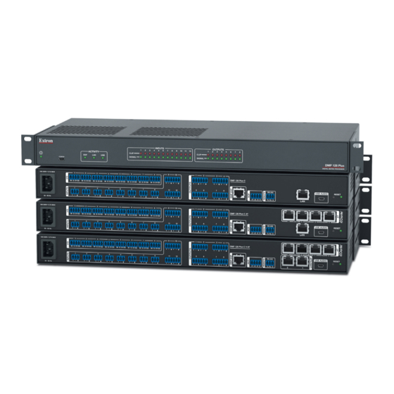
- Page 1 User Guide Audio Products Mixers and Processors DMP 128 Plus 12x8 ProDSP Digital Matrix Processor 68-2826-01 Rev. C 08 17...
-
Page 2: Safety Instructions
Safety Instructions Safety Instructions • English Istruzioni di sicurezza • Italiano WARNING: This symbol, , when used on the product, is intended to AVVERTENZA: Il simbolo, , se usato sul prodotto, serve ad alert the user of the presence of uninsulated dangerous voltage within avvertire l’utente della presenza di tensione non isolata pericolosa the product’s enclosure that may present a risk of electric shock. - Page 3 ついては、 エクス トロンのウェブサイ ト より 『Extron Safety www.extron.com and Regulatory Compliance Guide』 (P/N 68-290-01) をご覧ください。 Copyright © 2017 Extron Electronics. All rights reserved. Trademarks All trademarks mentioned in this guide are the properties of their respective owners. The following registered trademarks( ®...
- Page 4 FCC Class A Notice This equipment has been tested and found to comply with the limits for a Class A digital device, pursuant to part 15 of the FCC rules. The Class A limits provide reasonable protection against harmful interference when the equipment is operated in a commercial environment.
-
Page 5: Conventions Used In This Guide
Conventions Used in this Guide Notifications The following notifications are used in this guide: CAUTION: Risk of minor personal injury. ATTENTION : Risque de blessure mineure. ATTENTION: • Risk of property damage. • Risque de dommages matériels. NOTE: A note draws attention to important information. TIP: A tip provides a suggestion to make working with the application easier. -
Page 6: Table Of Contents
Input Filter Block ..........26 Input AEC Block (C Models Only) ....28 About this Guide ..........1 Input Dynamics Blocks ........32 About the DMP 128 Plus ........1 Input Delay Block ........... 37 Features .............. 2 Input Ducking Block ........38 Application Diagram .......... - Page 7 Virtual Send Bus ..........66 Overview ............107 Downloading and Installing Dante Controller ..108 Configuration Tools ........67 Configuring the DMP 128 Plus AT in Dante Presets .............. 67 Controller ............110 Methods for Marking Items ......68 Device Name ..........110 Configuring Presets ........
- Page 8 DMP 128 Plus Web Page ....... 164 Accessing the Embedded Web Page ... 164 Using the Web Page ........165 DMP 128 Plus VoIP Web Page ......167 Accessing the Embedded VoIP Web Page ... 167 Using the VoIP Web Page ......168 Special Characters ..........
-
Page 9: Introduction
DMP 128 Plus input and output expansion capabilities. DMP 128 Plus V models can register up to 8 VoIP lines per device. The DMP 128 Plus V can function as a VoIP interface, removing the need for dedicated VoIP hardware. -
Page 10: Features
• VoIP capability supporting Session Initiation Protocol (V models only) — A single DMP 128 Plus V model can be used for a single VoIP line or as a VoIP farm for up to 8 rooms. •... -
Page 11: Application Diagram
Extron Ethernet VoIP SF 26CT Full-Range Ceiling Speakers Conference Table Credenza Ethernet Extron Audio DMP 128 Plus C V Digital Matrix Processor Table 100-240V 0.7A MAX Microphones DMP 128 Plus C V O1 O2 O1 O2 O1 O2 O1 O2... -
Page 12: Installation
DMP 128 Plus C V AT 12x 8 ProDSP Processor with AEC, VoIP and Dante Mounting The 1U high, full rack width, 8.5 inch deep DMP 128 Plus mounts in the following manners: • Rack mounting — Attach the DMP 128 Plus to a standard 19-inch rack shelf. The following Underwriters Laboratories (UL) guidelines pertain to the installation of the DMP 128 Plus in a rack:... -
Page 13: Rear Panel Features And Cabling
Rear Panel Features and Cabling 100-240V 0.7A MAX DMP 128 Plus C V AT O1 O2 O1 O2 O1 O2 O1 O2 O1 O2 O1 O2 O1 O2 O1 O2 (SEC) (PRI) USB AUDIO RS-232 RESET -S G 50 - 60 Hz... - Page 14 RS-232 Port — Use a 3-pole 3.5 mm captive screw connector to connect the host RS-232 cable for bidirectional RS-232 (±5V) serial control (see figure 9 below for wiring). The default baud rate is 38400. RS-232 Transmit Receive Ground Tx Rx G Figure 9. RS-232 Wiring Example DMP 128 Plus • Installation...
- Page 15 AT Ports (AT models only) — Four RJ-45 ports form a Gigabit switch for use with a Dante network. The AT ports use Dante protocol for digital audio transport (AT) and allow the DMP 128 Plus AT to connect to a Dante audio network to form a larger matrix (see Dante Controller on page 107).
-
Page 16: Front Panel Features
DMP 128 Plus Front Panel -S G 50 - 60 Hz Power LED — Blinks during boot up and lights steadily when the DMP 128 Plus is operational. USB Config Port — One USB mini type B port is used for configuration. The USB config port can also be used for firmware updates. -
Page 17: Hardware Reset Modes
All audio inputs are set to unity gain • All outputs are unmuted and set to unity gain • Any inserted or active DSP is removed All preset and group master memory is cleared • DMP 128 Plus • Installation... -
Page 18: Dsp Configurator Software
DSP Configurator Software The DMP 128 Plus has no front panel hardware controls. To configure and operate the DMP 128 Plus, use a PC running Microsoft Windows 7 or newer and Extron ® ® DSP Configurator software. This section describes Extron DSP Configurator software and covers the following topics: •... - Page 19 Figure 13. DSP Configurator Download Center Page To run DSP Configurator from the default install location, click Start > Programs > Extron Electronics > DSP Configurator > DSP Configurator DMP 128 Plus • DSP Configurator Software...
-
Page 20: Accessing The Dsp Configurator Help File
From the DSP Configurator splash screen drop-down menu (see figure 14, below), select the model of DMP 128 Plus being connected to the host PC and click ( Figure 14. DSP Configurator Splash Screen Accessing the DSP Configurator Help File... -
Page 21: Menu Bar
Save closing the software. Click to save the file. Click to exit the application without saving. Click to return to the main workspace and keep the software running. Cancel DMP 128 Plus • DSP Configurator Software... -
Page 22: Edit
AT levels. Show All Channels — Individual channels can be hidden by user selection. This provides options for the user to select which input and output groups are visible in the main workspace. DMP 128 Plus • DSP Configurator Software... -
Page 23: Tools
Device Manager Device Manager page 81). Issue RESET Command — Clears the DMP 128 Plus of all processors and other configuration settings. This command does not reset general settings such as IP address. Firmware Loader — Opens the Firmware Loader application, if it is installed (see ¢... -
Page 24: Window
Dante network (see Dante Controller on page 107). Expansion Bus – Contains a submenu to assign a DMP 128 Plus as a Primary or § Secondary unit. On DMP 128 Plus AT models, the submenu can assign the expansion... -
Page 25: Macros Drop-Down
Live mode. Presets with an asterisk next to them are on the DMP 128 Plus, but not in the current configuration file. Run a preset to load it into the configuration file. Alternatively, perform a backup to run all presets and... -
Page 26: Live And Emulate Panel
NOTE: Not all menu options or actions are available in Emulate mode. Live Mode Enter Live mode to connect to a DMP 128 Plus and push or pull configurations between the device and host PC. In Live mode, changes made in DSP Configurator are directly applied to the DMP 128 Plus. - Page 27 DSP Configurator main workspace. Push — Pushes the configuration file, presets, macros, and ACP configurations open in DSP Configurator to the connected DMP 128 Plus. This will overwrite any configuration currently on the device.
- Page 28 Figure 31. Preset Selection Dialog Box Once a push or pull is completed, the current state of the connected DMP 128 Plus is displayed in the DSP Configurator status panel and the device is ready for further configuration. Exit Live Mode and Enter Emulate Mode...
-
Page 29: Dsp Configurator Inputs
Expansion and AT Inputs • • page 53 Mic/Line Inputs The twelve mic/line input channels on the DMP 128 Plus are shown in DSP Configurator under the panel (see figure 34). Inputs Figure 34. Inputs Panel Inputs 1 - 8 offer AEC (Acoustic Echo Cancellation) DSP capability (C models only) and phantom power. -
Page 30: Naming An Input Channel
Building Blocks Building Block Folders Delete a Building Block Button General Building Blocks New Folder Button Add a Building Block Button Building Blocks Help Button Figure 39. Input Building Blocks Dialog Box DMP 128 Plus • DSP Configurator Software... - Page 31 Building Blocks dialog box. Building Blocks Help Button — Opens the topic of the Building Blocks DSP Configurator Help file. This topic contains more information on the different types of building blocks for inputs and outputs. DMP 128 Plus • DSP Configurator Software...
-
Page 32: Input Processing
1 - 8. Figure 43. Input Processing Chain for Inputs 9 - 12 Input Gain Block Double-click the block to open the dialog box. Input Gain Input Gain Figure 44. Input Gain Block DMP 128 Plus • DSP Configurator Software... - Page 33 Input Gain closes the dialog box. Input Gain Help Button — Opens the topic in the ¤ Mic/Line Input Gain DSP Configurator Help file for further assistance in configuring input gain. DMP 128 Plus • DSP Configurator Software...
-
Page 34: Input Filter Block
High Pass Filter Filter instead of . If multiple filters are applied, the block displays HIGH PASS FILT Filter FILT over a dark green field. Figure 48. Filter Block Icons DMP 128 Plus • DSP Configurator Software... - Page 35 Parametric • Loudness Notch • NOTE: See the DSP Configurator Help file for more information on each of the filters. Click the button to open the help file topic discussing filters. Filters Help DMP 128 Plus • DSP Configurator Software...
-
Page 36: Input Aec Block (C Models Only)
Therefore, the amount of signal from the far end picked up by the mic is dependent on how much far end signal is being amplified in the near end room and the distance from the mic to the speakers. DMP 128 Plus • DSP Configurator Software... - Page 37 Activity Panel Bypass Button ERL Meter OK Button ERLE Meter Cancel Button TER Meter Show/Hide Advanced Options Button ¢ Reference Selection Drop-Down AEC Help Button £ Noise Cancellation Panel Figure 52. AEC Dialog Box DMP 128 Plus • DSP Configurator Software...
- Page 38 AEC processor (see AEC Advanced Options on the next page). AEC Help Button — Opens the topic of the £ Acoustic Echo Cancellation DSP Configurator Help file for further assistance in operating AEC processor. DMP 128 Plus • DSP Configurator Software...
- Page 39 AEC is engaged. Comfort Noise Text Box — Provides an ambient noise signal to prevent states of complete silence that may be perceived as a failed or dropped connection. 0 dB is the default. DMP 128 Plus • DSP Configurator Software...
-
Page 40: Input Dynamics Blocks
If a dynamics processor has been inserted and needs to be changed to a different dynamics processor, right-click the dynamics block, hover over , and select a new processor Insert to insert it (see figure 56 below). Figure 56. Changing Dynamics Processors DMP 128 Plus • DSP Configurator Software... - Page 41 Dynamics Help Button — Opens the topic of the Dynamics Operation DSP Configurator Help file for further assistance in operating dynamics processors. DMP 128 Plus • DSP Configurator Software...
- Page 42 Compressor closes the dialog box. Dynamics Help Button — Opens the topic of the Dynamics Operation DSP Configurator Help file for further assistance in operating dynamics processors. DMP 128 Plus • DSP Configurator Software...
- Page 43 Limiter closes the dialog box. Dynamics Help Button — Opens the topic of the Dynamics Operation DSP Configurator Help file for further assistance in operating dynamics processors. DMP 128 Plus • DSP Configurator Software...
- Page 44 Noise Gate closes the dialog box. Dynamics Help Button — Opens the topic of the Dynamics Operation DSP Configurator Help file for further assistance in operating dynamics processors. DMP 128 Plus • DSP Configurator Software...
-
Page 45: Input Delay Block
Bypass Button — Bypasses the delay. When the button is red, bypass is enabled. Delay Help Button —Opens the topic of the Delay Operation DSP Configurator Help file for further assistance in understanding operating the delay processor. DMP 128 Plus • DSP Configurator Software... -
Page 46: Input Ducking Block
If a ducking processor has been inserted and needs to be changed to a an adaptive gain processor, or vice versa, right-click the block and hover over to insert a different Insert processor (see figure 65 below). Figure 65. Changing Ducking Processor DMP 128 Plus • DSP Configurator Software... - Page 47 66 above). Channels with adaptive gain processors (AG) Mic 4 cannot be selected from this dialog box. Ducking Operation Help Button —Opens the topic of the Ducking Operation DSP Configurator Help file for further assistance in ducker configuration. DMP 128 Plus • DSP Configurator Software...
-
Page 48: Input Automix Block
DSP Configurator Help file for further assistance in adaptive gain configuration. Input Automix Block Double-click the block to open a drop-down menu. Select to insert Automix Auto-mixer the automix processor into the block. Figure 68. Automix Block and Drop-Down DMP 128 Plus • DSP Configurator Software... - Page 49 Automix Automix Help Button — Opens the topic of the DSP Configurator Help file ¤ Automix for further assistance in configuring the automix processor. DMP 128 Plus • DSP Configurator Software...
-
Page 50: Input Pre-Mixer Gain Block
Mute Button — Mutes signal at the pre-mixer stage, preventing it from reaching the mix matrices. OK Button — Confirms changes made to the contained parameters and closes the dialog box. Pre-mixer Gain DMP 128 Plus • DSP Configurator Software... -
Page 51: Aux Inputs
Eight Aux inputs are available with processing. These inputs can be assigned as one of the following: • Player inputs that play audio files stored in the DMP 128 Plus internal memory (see Player Input on the next page) •... -
Page 52: Aux Input Building Blocks
Aux input source: • Player — Plays audio files stored on the DMP 128 Plus internal memory. USB — Receives audio input from the rear panel USB port. •... - Page 53 USB 2 The DMP 128 Plus appears both as a communications and as a playback audio device in the operating system of the host computer. Select the DMP 128 Plus as the output device for both communication audio and playback audio to route audio from the host computer to the DMP 128 Plus via the rear panel USB audio port.
-
Page 54: Aux Input Filter Block
One filter block is available for each Aux input channel. This filter block functions the same as the mic/line input filter block (see Input Filter Block on page 26 for information on configuring the Aux input filter block). DMP 128 Plus • DSP Configurator Software... -
Page 55: Aux Input Dynamics Block
These channels can be used in a number of applications. For example, they can act as an AEC reference channel or be used for sub-mix processing. Figure 80. Virtual Returns Input Panel DMP 128 Plus • DSP Configurator Software... -
Page 56: Renaming A Virtual Return
Virtual returns E through P contain the following signal processing chain: Virtual Return Filter Block Virtual Return Dynamics Block Virtual Return Delay Block Virtual Return Pre-Mixer Gain Block NOTE: Only Virtual Return channels A through D contain Feedback Suppression processing blocks. DMP 128 Plus • DSP Configurator Software... -
Page 57: Virtual Return Feedback Suppressor Block
Feedback Suppressor Dialog Box dialog box contains three tabs for configuring feedback Feedback Suppressor suppression. • Settings Tab on the next page Dynamic Filters Tab on page 51 • • Fixed Filters Tab on page 52 DMP 128 Plus • DSP Configurator Software... - Page 58 Cancel Button — Reverts any changes made to the contained parameters back to ¢ their states when the current instance of the dialog box was Feedback Suppressor opened and closes the dialog box. DMP 128 Plus • DSP Configurator Software...
- Page 59 Cancel Button — Reverts any changes made to the contained parameters back to ¢ their states when the current instance of the dialog box was Feedback Suppressor opened and closes the dialog box. DMP 128 Plus • DSP Configurator Software...
-
Page 60: Virtual Return Filter Block
One dynamics block is available for each virtual return channel. This block functions the same as the mic/line input dynamics block (see Input Dynamics Blocks on page 32 for information on configuring the virtual return dynamics block). DMP 128 Plus • DSP Configurator Software... -
Page 61: Virtual Return Delay Block
(AT models only). The DMP 128 Plus can receive 16 channels of audio via the EXP port and 48 channels of audio via Dante (AT models only). On a DMP 128 Plus AT model, AT inputs 33 through 48 can be used for the EXP inputs Expansion Bus allowing use of the Dante network and the EXP port simultaneously (see page 93). -
Page 62: Expansion And At Inputs Overview
Expansion Bus on page 93). This synchronizes the sampling clocks of the two units. AT inputs allow a DMP 128 Plus AT model to receive signal from the audio network. Network audio routing is done with Dante Controller (see Dante Controller on page 107). - Page 63 Virtual Returns to EXP Outputs Virtual Returns to Virtual Sends EXP Inputs to Line and ¢ Aux Outputs EXP Inputs to EXP £ Outputs EXP Inputs to Virtual ¤ Sends Figure 92. DSP Configurator Mix Matrices DMP 128 Plus • DSP Configurator Software...
-
Page 64: Mix-Point Dialog Box
Mix-point Cancel Button — Reverts any changes made to the contained parameters back to their states when the current instance of the dialog box was opened and Mix Point closes the dialog box. DMP 128 Plus • DSP Configurator Software... -
Page 65: Mix-Point Context Menu
These outputs receive signal when mix-point connections are made between an input and an output in the mix-matrices. Each output panel can be expanded or collapsed by clicking the (expand) or (collapse) buttons. DMP 128 Plus • DSP Configurator Software... -
Page 66: Outputs
Outputs level analog outputs. Signal routed to these outputs can also be transmitted onto the Dante network on DMP 128 Plus AT models. Figure 95. Outputs Panel Naming an Output Click the output name field. -
Page 67: Output Building Blocks
New Folder Button —Creates a new folder or sub-folder. Building Blocks Help Button — Opens the topic of the Building Blocks DSP Configurator Help file. This topic contains more information on the different types of building blocks for inputs and outputs. DMP 128 Plus • DSP Configurator Software... -
Page 68: Output Processing
Post-mixer Trim Cancel Button — Reverts any changes made to the contained parameters back to their states when the current instance of the dialog box was opened Post-mixer Trim and closes the dialog box. DMP 128 Plus • DSP Configurator Software... -
Page 69: Output Delay Block
Output Attenuation Text Box — Allows the user to enter a gain or attenuation value in 0.1 dB steps. dBFS Meter — Provides post-attenuation and pre-mute a readout of the output signal level. DMP 128 Plus • DSP Configurator Software... -
Page 70: Aux Outputs
<Enter> output name. Press the to navigate to and highlight the next name field. <Down Arrow> Figure 110. Renamed Aux Output NOTE: Follow the same procedure to edit an Aux output name. DMP 128 Plus • DSP Configurator Software... -
Page 71: Aux Output Processing
Aux output. For example, if VoIP Line 1 is assigned to Aux input 1, VoIP line 1 is automatically assigned to Aux output 1 as well. Aux outputs can be reassigned to a different VoIP line. DMP 128 Plus • DSP Configurator Software... -
Page 72: Expansion Outputs
<Enter> output name. Press the to navigate to and highlight the next name field. <Down Arrow> Figure 116. Renamed Expansion Output NOTE: Follow the same procedure to edit an Expansion output name. DMP 128 Plus • DSP Configurator Software... -
Page 73: Expansion Output Processing
Expansion Output Attenuation Block Each expansion output contains an attenuation block. This block functions the same as the output attenuation block (see Output Attenuation Block on page 61 for information on configuring the expansion output dynamic filter). DMP 128 Plus • DSP Configurator Software... -
Page 74: Virtual Send Bus
Virtual Return B Virtual Return A cannot be routed to itself via the virtual send bus, and so on (see figure 119 below). Figure 119. Virtual Send Bus for Virtual Returns DMP 128 Plus • DSP Configurator Software... -
Page 75: Configuration Tools
(see figure 121 below). This option is only available if items are marked. Figure 121. Preset Save Message Clear Marked Items — Unmarks all currently marked elements. DMP 128 Plus • Configuration Tools... -
Page 76: Methods For Marking Items
Figure 123. Save a Preset Dialog Box NOTE: When a configuration file is pushed to a DMP 128 Plus, presets contained within that file are available for recall from DSP Configurator or SIS commands. The preset is saved and is available from the... -
Page 77: Groups
Delete Current Group Button — Select a group from the drop-down Select Group menu and click to delete the group. Delete Current Group Close Button — Click to close the dialog box. Any changes that have not been Close applied will be lost. DMP 128 Plus • Configuration Tools... -
Page 78: Configuring Groups
Confirm the group number and name from the dialog box Confirm Group Details (see figure 127, below). Click to confirm all details and create the group ( Figure 127. Confirm Group Details Dialog Box DMP 128 Plus • Configuration Tools... - Page 79 Choose the group from the drop-down ( Select Group Click Change Name From the dialog box, enter the new group number or group name Change Group Name into the respective fields ( Click Figure 128. Editing a Group DMP 128 Plus • Configuration Tools...
-
Page 80: Digital I/O
Digital I/O The DMP 128 Plus rear panel has eight sets of digital I/O ports (see figure page 5). Each set has one digital input and two digital outputs. These digital I/O ports can be configured from DSP Configurator. The dialog box allows... -
Page 81: Configuring Digital I/O
Figure 131. Selecting Digital In Acting Upon From the panel, select a mode for the digital output from the Digital Out 1 Mode drop-down. Figure 132. Selecting Digital Out 1 Mode DMP 128 Plus • Configuration Tools... - Page 82 Follow the Digital I/O configuration steps listed starting on while in Emulate mode. Connect to a DMP 128 Plus in Live mode and perform a configuration file push (see Live and Emulate Panel on page 18). DMP 128 Plus • Configuration Tools...
-
Page 83: Players
Figure 134. Configure Players Dialog Box Files in the Device — Lists the audio files stored on the DMP 128 Plus. The file names and extensions are listed in the column, with the size of the file listed in the Filename column. -
Page 84: Configuring Players
Configuring Players To upload an audio file: Enter Live mode to connect to a DMP 128 Plus (see Live and Emulate Panel page 18). Click Tools > Configure Players From the dialog box, click (see Configure Players Add File to Device... - Page 85 To stop the player, highlight the player with a single click, then click Stop Player To clear the player of its audio file, highlight the player with a single click, then click Clear Player Figure 139. Starting, Stopping, and Clearing Players DMP 128 Plus • Configuration Tools...
-
Page 86: Macros
Macros Macros are sets of actions that can affect the local DMP 128 Plus as well as other Extron products on the same TCP/IP network. They can be configured in Emulate or Live mode via an Ethernet connection only, and either saved to a configuration file or pushed onto DMP 128 Plus internal memory. -
Page 87: Configuring A Macro
When all of the action selections are configured, a new line appears at the bottom of the form so another action can be configured. From the drop-down, select whether the DMP 128 Plus waits for an SIS Next Command response from each action before executing the next action in the macro or executes the next command immediately without waiting for an SIS response. - Page 88 Connect Live to the DMP 128 Plus and click to push it to the Push Macro to Device DMP 128 Plus. Once the macro has been pushed, it can be run via DSP Configurator, a control system, or SIS commands. NOTES: •...
-
Page 89: Device Manager
If the device is connected via LAN, the device IP is displayed. Double-clicking a device in this list will initiate a pull (see Connect to a DMP 128 Plus in Live Mode on page 18). -
Page 90: Managing Devices In Device Manager
Connect dialog box and directly connect with a device. When connecting directly, to device... DSP Configurator performs a pull of the newly connected device configuration. Click Figure 144. Selecting a Device to be Added DMP 128 Plus • Configuration Tools... -
Page 91: Connect To Or Disconnect From Device
DSP Configurator from the current device Disconnect from Device when selected, and returns to Emulate mode. For detailed instructions on connecting to a DMP 128 Plus see Connect to a DMP 128 Plus in Live Mode on page 18. For detailed instructions on disconnecting from a DMP 128 Plus see... -
Page 92: Downloading Firmware Updates
(see Download figure 146, below). From the page, select the link ( ) near the middle of the page. Download Firmware Figure 146. Download Page and Firmware Link DMP 128 Plus • Configuration Tools... - Page 93 Download installer (see figure 148, below). Alternatively, select ) to save the firmware Save installer and install the firmware at a later time. Figure 148. Firmware Installer Run or Save DMP 128 Plus • Configuration Tools...
- Page 94 (see figure 149, below). Figure 149. Firmware Upgrade InstallShield The terms of installation must be agreed to. Select the radio button (see I accept... figure 150, below). Click Next Figure 150. Firmware License Agreement DMP 128 Plus • Configuration Tools...
-
Page 95: Organize Building Blocks
Building blocks in the Organize dialog are organized into folders for easily locating building blocks for a Building Blocks multitude of applications. Select to open the Tools > Organize Building Blocks Organize Building Blocks dialog box. DMP 128 Plus • Configuration Tools... - Page 96 Click a building block name twice to edit the building block name. Click a folder name twice to edit the name of the folder. DMP 128 Plus • Configuration Tools...
-
Page 97: Device Settings
Click to save Apply the changes. NOTE: Changing DHCP from resets the IP address to the factory default (192.168.254.254). Figure 154. IP Settings Tab in Devices Settings Dialog Box DMP 128 Plus • Configuration Tools... -
Page 98: Passwords
RS-232 Serial Settings port. Click to save the changes. Apply NOTE: The recommended baud rate for the DMP 128 Plus is 38400. Figure 156. Serial Settings Tab in Device Settings Dialog Box DMP 128 Plus • Configuration Tools... -
Page 99: Date/Time
(default). NOTE: The information displayed in the tab is static. In order to update the Date/Time information to reflect the current time, click Refresh Figure 157. Date/Time Tab in Device Settings Dialog Box DMP 128 Plus • Configuration Tools... -
Page 100: Dante Device
Dante Device to the right of the tab. This tab allows the DMP 128 Plus Dante settings to be Date/Time configured within DSP configurator without opening Dante Controller. ATTENTION: It is essential that a Dante device be named immediately after it is connected to the Dante network and before audio connections with other devices are established. -
Page 101: Options
There are two different procedures for setting up DMP 128 Plus for EXP communication. The first procedure describes how to set up a DMP 128 Plus non-AT model with another EXP-enabled non-AT device for EXP communication (see... - Page 102 NOTE: If both devices are configured as primary or secondary, an EXP connection cannot be established. Use a CAT 6 cable (such as the 1 foot cable included with the DMP 128 Plus) to connect the two rear panel EXP ports.
- Page 103 If both devices are configured as primary, an EXP connection cannot be established. Use a CAT 6 cable (such as the 1 foot cable included with the DMP 128 Plus) to connect the two rear panel EXP ports. When the connection is established, the front panel EXP LED on the primary unit lights steadily and the EXP LED on the secondary unit blinks rapidly.
-
Page 104: Phone Dialer
Tools>Phone Dialer Phone Dialer NOTES: • DSP Configurator must be connected Live to a DMP 128 Plus V model in order for dialog to be opened. Phone Dialer • VoIP lines must be registered with the call server via the DMP 128 Plus VoIP Web... -
Page 105: Placing A Call With The Phone Dialer
Placing a Call with the Phone Dialer NOTE: VoIP lines must be registered with the call server via the DMP 128 Plus VoIP Web page (see DMP 128 Plus VoIP Web Page on page 167) and assigned to an Aux input and output (see Aux Inputs on page 43). -
Page 106: Audio Control Panels (Acp)
(ACP) Extron Audio Control Panels (ACP) are configurable control interfaces for use with the DMP 128 Plus. ACP panels connect to the rear panel ACP port of a DMP 128 Plus via a 4-pole 3.5 mm captive screw connector (see figure on page 5). -
Page 107: Panel Id
Panel ID # Panel ID numbers (ID #) are used to identify ACP panels connected to the DMP 128 Plus and are necessary for the panel to function. The ID # is set using the DIP switch assembly on the physical ACP panel. Once the panel ID has been set on the physical device, the... -
Page 108: Action-Follow Selector
Mute and Gain groups for all microphone channels. • Mute and Gain groups for all program channels. Mute and Gain groups for each individual program source. • • Mute group for all output attenuation blocks. DMP 128 Plus • Audio Control Panels... -
Page 109: Acp 100 Configuration Example
ACP 100 Configuration Example From the DMP 128 Plus main workspace in DSP Configurator, select . The dialog box opens. Tools > Configure ACP Panels Configure ACPs Select an empty tab from the top of the dialog box to build a new configuration (see figure 166, below). - Page 110 LED Behavior Red reflects Mute On the button red when mute is engaged, or to turn the White reflects Mute On button white when mute is engaged. Figure 167. Mute Button Configuration DMP 128 Plus • Audio Control Panels...
-
Page 111: Acp 106 Style Configuration Example
Push the configurations to the DMP 128 Plus (see Saving and Pushing ACP Configurations on page 106). ACP 106 Style Configuration Example From the DMP 128 Plus main workspace in DSP Configurator, select . The dialog box opens. Tools > Configure ACP Panels Configure ACPs... - Page 112 From the drop-down ( ), select the mute group containing all Mute Master output channels. was chosen, the button is fully configured. Action-Follow Selector Figure 170. Configuring Mute Off and Mute On Buttons DMP 128 Plus • Audio Control Panels...
- Page 113 (see Managing Groups Devices in Device Manager on page 82). From the drop-down ( ), select the mute group containing all Mute Master ¨ microphone source channels. DMP 128 Plus • Audio Control Panels...
-
Page 114: Saving And Pushing Acp Configurations
Save the configuration file. ACP configurations are saved with the configuration file. Connect Live to a DMP 128 Plus via a LAN (TCP/IP) connection. NOTE: The host computer must be connected to the DMP 128 Plus LAN port in order to push ACP configurations to the device. -
Page 115: Dante Controller
Dante Troubleshooting Overview DMP 128 Plus AT devices (DMP 128 Plus AT, C AT, and C V AT) use Dante technology by Audinate to provide high performance digital audio networking over standard TCP/IP networks. The Dante Controller software application is used to route audio on the network. -
Page 116: Downloading And Installing Dante Controller
7 or newer. For full details about computer requirements and ® ® to download the software, see the Dante Controller product page at www.extron.com To download Dante Controller: On the Extron Electronics Web page, click the tab (see figure 173, Download below). The page opens. Download... - Page 117 If you choose to run the file, follow all prompts. If you saved the file, click the saved file to begin installation when ready. The installed Dante Controller program files are saved in: C:\Program Files (x86)\Audinate\Dante Controller\DanteController.exe DMP 128 Plus • Dante Controller...
-
Page 118: Configuring The Dmp 128 Plus At In Dante Controller
Configuring the DMP 128 Plus AT in Dante Controller Use a standard Ethernet cable to connect the DMP 128 Plus AT to a Dante network via the rear panel AT port (see figure on page 5) and power the device. Device Name Multiple devices on the same Dante network can present difficulty in identifying individual devices. -
Page 119: Renaming The Dmp 128 Plus At In Dante Controller
NOTE: Dante device naming can also be done via DSP Configurator (see Dante Device on page 92). Ensure that the control computer and a single DMP 128 Plus AT are connected to the same network. From the control computer menu select: Start All Programs >... - Page 120 ) to confirm the new name, then close the dialog Device Configuration box. The new name is written to the Dante interface of the DMP 128 Plus AT. Repeat as necessary for all devices. NOTE: The device name assigned in Dante Controller only applies to the Dante interface and does not affect the device name recognized in DSP Configurator.
-
Page 121: Renaming A Receiver Or Transmitter
(see figure 181, above). The DMP 128 Plus AT receivers are labelled through because the DMP 128 Plus AT can EXP_In-01 EXP_In-48 receive signal at the 48 EXP inputs. Follow the instructions on the next page to rename a receiver. - Page 122 The second set of DMP 128 Plus AT transmitters is labelled through EXP-Out-01 because the DMP 128 Plus AT can transmit signal routed to the EXP outputs Exp_Out-16 to the Dante network. Follow the instructions on the next page to rename a transmitter.
-
Page 123: Finding A Dante Device Ip Address
DMP 128 Plus AT in Dante Controller on page 111). NOTE: If the DMP 128 Plus AT has not been renamed, its default name consists of the product name followed by a hyphen, plus the last 6 digits of the device MAC address... -
Page 124: Physical Dante Network Setup
3 other units. A larger network switch can be used in place of a central DMP 128 Plus AT, allowing more than four total units to be connected in the star topology. DMP 128 Plus C AT #2... -
Page 125: Redundant Configuration
USB AUDIO RS-232 RESET -S G Figure 187. Primary and Secondary AT Ports To configure the DMP 128 Plus in redundant mode using Dante Controller: Open Dante Controller. Press on the keyboard to access the dialog box. <Ctrl+D> Device View Select the desired DMP 128 Plus AT from the (Choose a Dante Device...) -
Page 126: Dante Controller Operation
Receivers take in digital audio from the audio network into the device. DMP 128 Plus AT Transmitters and Receivers In the DMP 128 Plus AT, the line output and EXP output channels are Dante transmitters because their audio output is transmitted onto the Dante network. Routing an analog output to the Dante network allows the signal to be output on both analog and Dante simultaneously, the same is true for the EXP outputs. -
Page 127: Dante Routing Operation
Routing Devices After the DMP 128 Plus AT is configured, the channels can be routed to the other Dante devices on the audio network. Channels transmitted to the network or received from the network are routed using the Dante Controller... -
Page 128: Disconnecting Inputs From Outputs
5 seconds before disconnecting or powering down the devices. This ensures that the new information is properly saved to those devices. Device level configuration such as sample rates, latency, and clock settings are saved instantly. DMP 128 Plus • Dante Controller... -
Page 129: Dante Troubleshooting
Check Dante Controller after each step to see if the problem is resolved. Click the icon (see figure 191, below). The Choose a Dante Interface Configure dialog box opens. Dante Interfaces Figure 191. Choose a Dante Interface Icon DMP 128 Plus • Dante Controller... -
Page 130: Restarting Dante Controller
, then from the menu ( Help Online Help Offline Help • Press the key on the computer keyboard for online help or for offline <F1> <Shift+F1> help. Figure 193. Accessing the Dante Help File DMP 128 Plus • Dante Controller... -
Page 131: Remote Communication And Control
(such as a control system) attached to the rear panel RS-232 port or LAN port, or the front panel USB Config port. The DMP 128 Plus can be set up and controlled using SIS commands or DSP Configurator software (see Installation on page 4 for pin assignments and details on the... -
Page 132: Rs-232 Port
RS-232 Port The DMP 128 Plus has a serial port that can be connected to a host device such as a computer running either the DataViewer or HyperTerminal utilities. The port makes serial control of the DMP 128 Plus possible. -
Page 133: Usb Config Port
USB Config Port The DMP 128 Plus has a front panel USB port that can be connected to a computer as a host device running either the HyperTerminal or DataViewer utilities for control of the device. Once a connection is established, SIS programming can begin (see... -
Page 134: Host-To-Device Communications
• If the DMP 128 Plus is off and RS-232 connection is already set up (the PC is cabled to the DMP 128 Plus and a serial communication program such as DataViewer is open), the connected unit sends these messages via RS-232 when first powered on. -
Page 135: Using The Command And Response Tables
SIS commands consist of a string (one or more characters per command field). No special characters are required to begin or end a command sequence. When the DMP 128 Plus determines a command is valid, it executes the command and sends a response to the host device. -
Page 136: Error Responses
Error Responses When the DMP 128 Plus is unable to execute the command, it returns an error response to the host. The error response codes and their descriptions are as follows: E10 — Unrecognized command E24 — Privilege violation E12 —... -
Page 137: Command And Response Table Sections
= (300 seconds) 65000 Firmware Query = Detailed version information (includes all 2Q, 3Q, and 4Q) = Firmware version = Final stage bootloader = Factory base code version = Updated firmware version DMP 128 Plus • Remote Control and Configuration... - Page 138 Time in 10s of milliseconds to wait for receive data before releasing the port to another source (min = , max = , and 650000 default = (100ms). Stop Bits (default) or DMP 128 Plus • Remote Control and Configuration...
- Page 139 Sunday = 1). Prefix (subnet mask bits) Subnet 255.255.0.0 is represented as a Prefix value of /16. X4& DHCP Status = off (default), = on X12) DMP 128 Plus • Remote Control and Configuration...
- Page 140 Responds with 4 asterisks (****) if password exists and empty if not, instead of actual password. Connection Security Level = User = Administrator NIC Number Network Interface Card number (only V models have 2 NICs) DMP 128 Plus • Remote Control and Configuration...
- Page 141 Backup/Restore Device Configuration Save device X3@] Cnfg1* configuration (to filesystem) Restore device X3@] Cnfg 0 * configuration Configuration type = IP configuration, = device-specific parameters NOTE: DMP 128 Plus • Remote Control and Configuration...
- Page 142 . Leading zeros in each of the 4 fields are op- xxx.xxx.xxx.xxx tional in setting values. NTP Status = disabled (default), = enabled. Ethernet Port Number = off, custom port numbers must be or higher. 1024 DMP 128 Plus • Remote Control and Configuration...
- Page 143 E SNMP setting NOTES: IP Address xxx.xxx.xxx.xxx . Leading zeros in each of the 4 fields are optional in setting values. Text Up to 64 characters. SNMP Access = disabled (default), = enabled DMP 128 Plus • Remote Control and Configuration...
- Page 144 View current time zone {zone name, TZON description} List all time zones {zone name, *TZON description} NOTES: Port Number (always for DMP 128 Plus) Port Mode = disabled, = standard, = device DMP 128 Plus • Remote Control and Configuration...
- Page 145 Macro number. If is not specified, the macro number defaults to the corresponding I/O channel number. Presets Preset number. If is not provided, the preset number defaults to the corresponding I/O channel number. DMP 128 Plus • Remote Control and Configuration...
- Page 146 I/O channel number. Signal Presence Input Number for signal presence monitoring. If is not speci- fied, the input number defaults to the corresponding I/O channel number. DMP 128 Plus • Remote Control and Configuration...
- Page 147 (outputs through are Aux outputs) EXP output number through New Name Invalid characters = ~ , @ = ‘ [ ] { } < > ` “ : ; | \ DMP 128 Plus • Remote Control and Configuration...
- Page 148 Play state = Stopped, = Playing Macro number through . Response will be padded with a leading 0. Macro status = Macro idle Macro name 24 characters maximum ( , and “ ”) DMP 128 Plus • Remote Control and Configuration...
-
Page 149: Dsp Sis Commands
• Aux Input (gain, mute, and source) • Post-mixer (gain only) Pre-mixer (gain and mute) Output (attenuation and mute) • • Figure 196. DSP Processors Addressable via SIS Commands (marked in green) DMP 128 Plus • Remote Control and Configuration... -
Page 150: Symbol Definitions
The DMP 128 rejects the following characters: {space (OK for names)} + ~ , @ = ‘ { } [ ] < > ` “ ; : \ ? DMP 128 Plus • Remote Control and Configuration... -
Page 151: Command And Response Table For Dsp Sis Commands
+10.4 dB would be entered as and a level return gain, post-mixer of -3.2 dB would be entered as trim, and output volume. Mute/Phantom power = disabled status = enabled DMP 128 Plus • Remote Control and Configuration... - Page 152 Group fader dB value in 0.1 dB steps to raise or lower a group fader. Gain uses X7& increase/decrease 10x multiplier (+10 dB = ). + or - goes after the number. 100+ DMP 128 Plus • Remote Control and Configuration...
- Page 153 Target OID on page 150 Group master group through number Group fader soft limit dB value in 0.1 dB steps. Gain uses 10x multiplier (+10 dB = 100+ Group type = gain = mute DMP 128 Plus • Remote Control and Configuration...
- Page 154 Gain value dB value in 0.1 dB steps. Gain uses 10x multiplier (+10 dB = 100, -3.4 dB = -34, and so on). Mute status 0 = off, 1 = engaged DMP 128 Plus • Remote Control and Configuration...
- Page 155 Gate Monitoring on page 42 for more information). Monitoring threshold = disabled, = signal threshold to monitor (-0.1 to 0001 1500 -150.0 dBFS). Meter value = 0.0 to -150.0 dBFS 0000 1500 DMP 128 Plus • Remote Control and Configuration...
-
Page 156: Command And Response Table For Voip Sis Commands
= fail Operating state = enable, = disable X& Auto answer mode = disabled, = delay (seconds), = follow SIP header Delay value Represents time in seconds. Hold status = off, = on-hold DMP 128 Plus • Remote Control and Configuration... - Page 157 = Inactive, = Active, = On Hold, = Incoming, = Outgoing Duration HH:MM:SS X1& Codec name Alphanumeric characters only Jitter in milliseconds Packet drop count Total packet count Extension number Valid characters are DMP 128 Plus • Remote Control and Configuration...
-
Page 158: Object Id (Oid) Number Tables
Virtual Return E 50104 Virtual Return M 50112 Virtual Return F 50105 Virtual Return N 50113 Virtual Return G 50106 Virtual Return O 50114 Virtual Return H 50107 Virtual Return P 50115 DMP 128 Plus • Remote Control and Configuration... -
Page 159: Output Path Oids
Aux Output 5 60112 Aux Output 5 60012 Aux Output 6 60113 Aux Output 6 60013 Aux Output 7 60114 Aux Output 7 60014 Aux Output 8 60115 Aux Output 8 60015 DMP 128 Plus • Remote Control and Configuration... -
Page 160: Automixer Oids
Aux Automixer 1 49012 Aux Automixer 5 49016 Aux Automixer 2 49013 Aux Automixer 6 49017 Aux Automixer 3 49014 Aux Automixer 7 49018 Aux Automixer 4 49015 Aux Automixer 8 49019 DMP 128 Plus • Remote Control and Configuration... - Page 161 59038 EXP Automixer 47 59046 EXP Automixer 40 59039 EXP Automixer 48 59047 NOTE: Automixer OIDs are used only to read unsolicited automixer gate status responses (see Automixer Gate Monitoring on page 42). DMP 128 Plus • Remote Control and Configuration...
-
Page 162: Mix-Point Oids
21018 21019 21020 21021 21022 21023 21024 21025 21026 21027 21028 21029 21030 21031 Mic 12 21116 21117 21118 21119 21120 21121 21122 21123 21124 21125 21126 21127 21128 21129 21130 21131 DMP 128 Plus • Remote Control and Configuration... - Page 163 21818 21819 21820 21821 21822 21823 21824 21825 21826 21827 21828 21829 21830 21831 Aux 8 21916 21917 21918 21919 21920 21921 21922 21923 21924 21925 21926 21927 21928 21929 21930 21931 DMP 128 Plus • Remote Control and Configuration...
- Page 164 23434 23435 23436 23437 23438 23439 23440 23441 23442 23443 23444 23445 23446 23447 Rtn P 23532 23533 23534 23535 23536 23537 23538 23539 23540 23541 23542 23543 23544 23545 23546 23547 DMP 128 Plus • Remote Control and Configuration...
- Page 165 24908 24909 24910 24911 EXP 15 25000 25001 25002 25003 25004 25005 25006 25007 25008 25009 25010 25011 EXP 16 25100 25101 25102 25103 25104 25105 25106 25107 25108 25109 25110 25111 DMP 128 Plus • Remote Control and Configuration...
- Page 166 28108 28109 28110 28111 EXP 47 28200 28201 28202 28203 28204 28205 28206 28207 28208 28209 28210 28211 28300 28301 28302 28303 28304 28305 28306 28307 28308 28309 28310 28311 EXP 48 DMP 128 Plus • Remote Control and Configuration...
- Page 167 25034 25035 25036 25037 25038 25039 25040 25041 25042 25043 25044 25045 25046 25047 EXP 16 25132 25133 25134 25135 25136 25137 25138 25139 25140 25141 25142 25143 25144 25145 25146 25147 DMP 128 Plus • Remote Control and Configuration...
- Page 168 28234 28235 28236 28237 28238 28239 28240 28241 28242 28243 28244 28245 28246 28247 28332 28333 28334 28335 28336 28337 28338 28339 28340 28341 28342 28343 28344 28345 28346 28347 EXP 48 DMP 128 Plus • Remote Control and Configuration...
- Page 169 25018 25019 25020 25021 25022 25023 25024 25025 25026 25027 25028 25029 25030 25031 EXP 16 25116 25117 25118 25119 25120 25121 25122 25123 25124 25125 25126 25127 25128 25129 25130 25131 DMP 128 Plus • Remote Control and Configuration...
- Page 170 28218 28219 28220 28221 28222 28223 28224 28225 28226 28227 28228 28229 28230 28231 EXP 48 28316 28317 28318 28319 28320 28321 28322 28323 28324 28325 28326 28327 28328 28329 28330 28331 DMP 128 Plus • Remote Control and Configuration...
- Page 171 29818 29819 29820 29821 29822 29823 29824 29825 29826 29827 29828 29829 29830 29831 EXP 64 29916 29917 29918 29919 29920 29921 29922 29923 29924 29925 29926 29927 29928 29929 29930 29931 DMP 128 Plus • Remote Control and Configuration...
-
Page 172: Web Pages
DMP 128 Plus VoIP Web Page Special Characters • The DMP 128 Plus can be accessed by a PC or control system using a rear panel Ethernet LAN port (non-V models) or LAN/VoIP port (V models only) and a Web browser such as Microsoft Internet Explorer. -
Page 173: Using The Web Page
IP address, subnet mask, and default gateway can Use DHCP not be edited. RS-232 Settings Panel — Provides a read-only display of device RS-232 settings. Device Info Panel — Displays general device information. DMP 128 Plus • Web Pages... - Page 174 Alternatively, click to open the Set Manually Date dialog box which allows the user to set date, time, and time zone and Time Settings information. Figure 202. Date and Time Settings Dialog Box DMP 128 Plus • Web Pages...
-
Page 175: Dmp 128 Plus Voip Web Page
IP address via DHCP, the default address is 192.168.254.254 Press <Enter> If a username and password have been set to access the basic DMP 128 Plus Web page, the same username and password are required to access the VoIP Web page. DMP 128 Plus • Web Pages... -
Page 176: Using The Voip Web Page
Audio DSP — Displays whether the line is assigned to an Aux channel in the • DMP 128 Plus (Configured) or the line is not assigned to an Aux channel (Not Configured) (see Aux Inputs on page 43 for more information). - Page 177 VLAN Configuration — This ribbon is only available when is selected from the VLAN drop-down. Use the fields to enter a VLAN IP configuration. VoIP Interface Apply Button — Click the button to commit interface changes to the device. Apply DMP 128 Plus • Web Pages...
- Page 178 Select the checkbox to read the voice VLAN ID from the network and VLAN ID automatically configure the DMP 128 Plus VLAN tag (VLAN must be selected as the interface for this feature to work). Select the checkbox to read PCP values from the network and Qos PCP automatically configure layer 2 QoS.
- Page 179 3 QoS. NOTE: VLAN ID, QoS PCP, and QoS DSCP values read from the network and applied to the DMP 128 Plus overwrite any manually specified values. Select the checkbox to send the DMP 128 Plus model number, part Inventory number, and firmware details to the network switch.
- Page 180 DMP 128 Plus. When the default certificate is selected, click Generate to force the DMP 128 Plus to self-generate a new local certificate and private key. NOTE: Certificates and private keys must be in the Privacy Enhanced Mail (PEM) format.
- Page 181 Apply NOTE: When changes are committed with the Apply button, network services on the DMP 128 Plus restart. This process can take up to 30 seconds. NOTE: For more information regarding VoIP network configuration, refer to the DMP 128 Plus product page on www.extron.com.
-
Page 182: Advanced Options
NOTE: If a port number is not entered, is used be default. 5060 Click ) to commit the changes to the DMP 128 Plus. Committing the changes Apply does not initiate line registration with the call server. Click ) to initiate registration with the call server. Registration is confirmed... - Page 183 To remove a codec from the column: Assigned Select the codec in the column ( Assigned Click the button between the two columns ( left arrow The codec moves from the column to the column ( Assigned Available DMP 128 Plus • Web Pages...
- Page 184 Delay (seconds) Field — If auto-answer is enabled, enter the amount of delay in seconds before the call is automatically answered. Apply Button — After configuring the dialing behavior of the selected line, click Apply to commit the changes to the line. DMP 128 Plus • Web Pages...
- Page 185 Clear Display Button — Clears all log data currently in the log window. Export Button — Exports the contents of the log window to a text file. The exported text file is automatically stored in the default download directory of the Web browser. DMP 128 Plus • Web Pages...
-
Page 186: Special Characters
VoIP configurations to a JSON file. These System configuration files are used to return DMP 128 Plus devices to a known VoIP configuration. Additionally, partial configurations (individual JSON fields) can be applied using the import tool. - Page 187 Extron Electronics makes no further warranties either expressed or implied with respect to the product and its quality, performance, merchantability, or fitness for any particular use. In no event will Extron Electronics be liable for direct, indirect, or consequential damages resulting from any defect in this product even if Extron Electronics has been advised of such damage.
Need help?
Do you have a question about the DMP 128 Plus and is the answer not in the manual?
Questions and answers