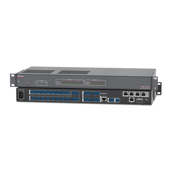
Extron electronics DMP 128 Plus Setup Manual
Hide thumbs
Also See for DMP 128 Plus:
- Setup manual (4 pages) ,
- User manual (187 pages) ,
- User manual (95 pages)
Advertisement
Quick Links
DMP 128 Plus • Setup Guide
This guide provides basic instructions for an experienced technician to install the DMP 128 Plus ProDSP
Processor. For more information, specifications, and the user guide, see the DMP 128 Plus product page on www.extron.com.
Disconnect Power and Mount the DMP 128 Plus
Disconnect power from the DMP 128 Plus and turn off all devices that will be connected to it. The DMP 128 Plus is housed in a
full rack width, 8.5 inch deep, 1U high metal enclosure that can be rack mounted or placed on a table with the provided rubber
feet. Select a suitable mounting location, then choose an appropriate mounting option. Mounting information can be found in the
DMP 128 Plus User Guide on www.extron.com.
Make all external device connections before applying power.
Rear Panel Connections
100-240V
0.7A MAX
1
2
3
IN
G
O1 O2
IN
G
O1 O2
IN
G
O1 O2
1
2
3
50 - 60 Hz
A
B
DMP 128 Plus Rear Panel
Figure 1.
AC Power — IEC power connector, 100—240 VAC, 50—60 Hz.
A
Digital I/O Ports — Connect up to eight 4-pole 3.5 mm captive screw connectors. These configurable digital input and
B
output ports are designed to connect to microphones with logic circuitry for mic mute and tally back functionality. Each port
provides a common ground.
Mic/Line Inputs — On inputs 1 through 8, use 3-pole 3.5 mm captive screw connectors to connect eight balanced or
C
unbalanced microphone or mono line level sources (see 3-pole Audio Input Wiring below). Inputs 1 through 8 provide
phantom power (all models) and AEC (C models only).
On inputs 9 through 12, use 6-pole 3.5 mm captive screw connectors to connect up to four balanced or unbalanced
microphone or mono line level sources or two stereo sources (see 6-pole Audio Input Wiring below).
3
" (5 mm) MAX. (typ)
16
Tip
Ring
Sleeve
Balanced Input
3-pole Audio INPUT Wiring
NOTES:
•
Balanced or unbalanced stereo sources can be connected to the
6-pole inputs.
•
When using the 5-pole CSR adapter, connect it so the far left plug
is inserted into the far left jack of the 6-pole input (see the example
to the right).
4
6
7
9
10
5
8
IN
G
O1 O2
IN
G
O1 O2
IN
G
O1 O2
IN
G
O1 O2
IN
G
O1 O2
11
12
4
5
6
7
8
C
Tip
Sleeve
Jumper
Unbalanced Input
1
2
3
4
DMP 128 Plus C V AT
5
6
7
8
RS-232
+V
+S
-S G
Tx
Rx
G
D
E
F
G
Tip
Ring
Sleeve
Tip
Ring
Sleeve
Balanced Input
6-pole Audio INPUT Wiring
5-pole CSR
Digital Matrix
™
I
1
2
3
(SEC)
(PRI)
4
USB AUDIO
RESET
2
1
H
J
K
Tip
Sleeve
Jumper
Tip
Sleeve
Jumper
Unbalanced Input
DO NOT
Connect Here
7
8
N
G
O 1
O 2
IN
9
G
O 1
7
O 2
1 0
8
1
1 1
1 1
2
1 2
1 2
3
4
5
6
D M
P 1
7
2 8
P l u
8
s C
V A
T
+ V
R S
+ S
- 2
- S
G
1
Advertisement

Summary of Contents for Extron electronics DMP 128 Plus
-
Page 1: Rear Panel Connections
Disconnect Power and Mount the DMP 128 Plus Disconnect power from the DMP 128 Plus and turn off all devices that will be connected to it. The DMP 128 Plus is housed in a full rack width, 8.5 inch deep, 1U high metal enclosure that can be rack mounted or placed on a table with the provided rubber feet. -
Page 2: Front Panel Features
(see the DMP 128 Plus User Guide for instructions on installation and operation). USB Audio Port — Connect a Windows or Mac computer to this USB mini type B port to interface with the DMP 128 Plus as a 4x4 USB audio device (see the DMP 128 Plus User Guide for USB audio interfacing capabilities). - Page 3 DMP 128 Plus Configuration When power is connected to the DMP 128 Plus and the rest of the audio system, audio output can easily be tailored to any listening environment. When configuration is required, changes are made using DSP Configurator.
- Page 4 Click Apply. Click OK to confirm changes and close the Device Settings dialog box. For more information on configuring a DMP 128 Plus AT model in Dante Controller, refer to the Dante Controller section of the DMP 128 Plus User Guide (www.extron.com). Extron Headquarters...


Need help?
Do you have a question about the DMP 128 Plus and is the answer not in the manual?
Questions and answers