Extron electronics DMP 64 Setup Manual
Hide thumbs
Also See for DMP 64:
- User manual (152 pages) ,
- Setup manual (2 pages) ,
- User manual (146 pages)
Advertisement
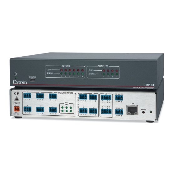
DMP 64 • Setup Guide
Disconnect Power and Mount the DMP 64
Disconnect power to the DMP 64 and turn off all devices connected to it. The DMP 64 is housed in a half rack width, 9.5 inches
deep, 1U high metal enclosure that can sit on a table with the provided rubber feet or can be rack mounted. Select a suitable
mounting location, then choose an appropriate mounting option.
DMP 64
POWER
12V
1.0A MAX
Connections
a
Connect the Power Supply — The included power supply is prewired.
Plug the captive screw connector into the DMP 64 power jack.
b
Mic/Line Inputs — Attach up to six microphone or mono line level
devices, balanced or unbalanced, to the DMP 64 using the audio input
wiring diagram shown at right.
c
Connect the Audio Outputs — For balanced or unbalanced mono audio
output, connect an audio output device to each of the four outputs. Wire
the connectors as shown in the audio output wiring diagram shown at
right.
d
Connect the I/O Ports — To control or monitor external devices, connect
up to six digital I/O ports (connections not shown). See the DMP 64 User
Guide for additional information.
e
Connect a Control System — There are three options to connect a
control system: LAN, RS‑232, and USB. Extron recommends using the
LAN port for configuration and remote control of the DMP 64.
LAN — Using a standard Ethernet cable, connect to a network via the LAN port (
table at right shows the default network settings.
NOTE:
To connect the DMP 64 directly to a computer, use a crossover Ethernet
cable.
RS-232 — Connect the host RS‑232 cable to the rear panel of the switcher (
provided 3‑pole captive screw connector (see the wiring diagram at right).
USB — Connect the host USB port to the front panel configuration port, (not shown), using
a USB A to mini‑B cable. The USB connection should be used only for configuration. Use
the RS‑232 or LAN port for remote control of the DMP 64.
When all connections have been made, power up the input and output devices, then apply
power to the DMP 64.
This guide provides basic instructions for an experienced technician
to install the DMP 64 ProDSP
DSP Configurator
DMP 64 User Guide found at www.extron.com.
1
2
3
MIC
+ 48V
1
2
6
4
5
4
5
™
Digital Matrix Processor and
software. For additional information see the
™
1
2
1 2 3 G
3
3
4
6
4 5 6 G
Tip
Ring
Sleeve
Balanced Input
Tip
Ring
Sleeve
Balanced Output
ATTENTION:
•
•
â
). The
à
) using the
RS-232 (1)
Tx Rx G
LAN
RESET
RS-232 (2)
Tx Rx G
3
" (5 mm) MAX. (typ)
16
Tip
Sleeve
Jumper
Unbalanced Input
Audio INPUT Wiring
Tip
NO Ground Here
Sleeve
Unbalanced Output
Audio OUTPUT Wiring
For unbalanced audio outputs, connect
the sleeves to ground.
DO NOT connect the sleeves to the
negative (–) contacts.
IP Address: 192.168.254.254
Subnet Mask: 255.255.0.0
Default Gateway: 0.0.0.0
DHCP: OFF
Do not tin
the wires!
RS-232
Device
Bidirectional
Transmit (Tx)
Transmit (Tx)
Receive (Rx)
Receive (Rx)
Ground (
)
Ground (
Tx
Rx
)
Advertisement
Table of Contents

Related Manuals for Extron electronics DMP 64


Summary of Contents for Extron electronics DMP 64
- Page 1 DMP 64 • Setup Guide This guide provides basic instructions for an experienced technician to install the DMP 64 ProDSP ™ Digital Matrix Processor and DSP Configurator software. For additional information see the ™ DMP 64 User Guide found at www.extron.com. Disconnect Power and Mount the DMP 64 Disconnect power to the DMP 64 and turn off all devices connected to it.
- Page 2 +1.919.850.1000 +86.21.3760.1568 +31.33.453.4040 +65.6383.4400 +91.80.3055.3777 +1.714.491.1517 FAX +1.919.850.1001 FAX +86.21.3760.1566 FAX +31.33.453.4050 FAX +65.6383.4664 FAX +91.80.3055.3737 FAX 68-1790-50 © 2013 Extron Electronics All rights reserved. All trademarks mentioned are the property of their respective owners. www.extron.com Rev. C 10 13...
Need help?
Do you have a question about the DMP 64 and is the answer not in the manual?
Questions and answers