Extron electronics AXI 22 AT Setup Manual
Audio expansion
interfaces
Hide thumbs
Also See for AXI 22 AT:
- User manual (45 pages) ,
- Setup manual (6 pages) ,
- User manual (42 pages)
Table of Contents
Advertisement
Quick Links
Download this manual
See also:
User Manual
AXI 22 AT and AXI 44 AT • Setup Guide
This guide provides basic instructions for an experienced technician to install the AXI 22 AT and AXI 44 AT Audio Expansion
Interfaces with Dante. For additional information and specifications, see the AXI 22 AT and AXI 44 AT product pages
at www.extron.com.
E
NOTE:
In this setup guide, the terms "AXI" and "device" are used to refer to the AXI 22 AT and the AXI 44 AT interchangeably.
CONTROL
GAIN LEVEL
+42
INPUT
+36
Disconnect Power and Mount the AXI
+30
1
+24
+18
2
CONFIG
+12
+6
Disconnect power from the AXI and turn off all devices that will be connected to it. The AXI is housed in a quarter rack width,
0
6 inch deep, 1U high metal enclosure that can be rack mounted or sit on a table with the provided rubber feet. Select a suitable
mounting location, then choose an appropriate mounting option. Mounting information can be found in the AXI 22 AT and
A
C
D
B
AXI 44 AT User Guide at www.extron.com.
Make all external device connections before applying power.
Rear Panel Connections
MIC / LINE INS
POWER
12V
1
2
0.5A MAX
A
B
12 VDC Power Inlet
A
Mic/Line Inputs
B
Line Outputs
C
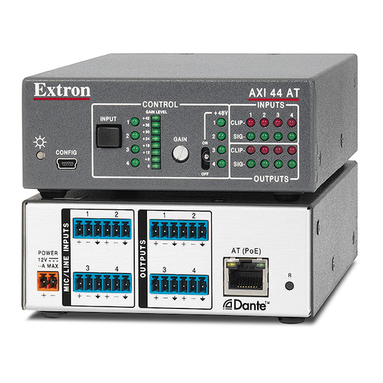
Figure 1.
AXI 22 AT and AXI 44 AT Rear Panel Connections
12 VDC Power Inlet — Connect the optional 12 VDC power supply to the rear panel captive screw connector and plug the
A
power cable into the IEC connector on the power supply (see figure 2 below and the attention notices on the next page). The
power LED on the front panel blinks as the unit is powering on and lights steadily when the unit is operational.
As an alternative to the optional external power supply, the AXI can be powered over Ethernet (PoE) using the AT (PoE) port.
Rear Panel
Power Receptacle
DC Power Cord
Captive Screw
Connector
Ridged
– Return
+12 VDC input
Smooth
Connecting the External Power Supply
Figure 2.
H
I
AXI 22 AT
INPUTS
1
2
CLIP -
+ 48V
1
SIG -
GAIN
ON
ON
2
CLIP -
SIG -
OFF
OFF
OUTPUTS
F
G
I
AT (PoE)
OUTPUTS
1
2
R
C
D
E
Ground
all devices.
External
Power Supply
12 VDC, 1 A max.
E
CONTROL
GAIN LEVEL
+42
INPUT
1
+36
+30
2
+24
GAIN
ON
ON
+18
3
CONFIG
+12
+6
4
0
OFF
OFF
A
C
D
B
F
G
1
2
1
2
POWER
12V
3
4
3
4
0.6A MAX
A
B
C
AT (PoE) Port
D
Reset Button
E
H
I
AXI 44 AT
INPUTS
+ 48V
1
2
3
4
1
CLIP -
2
SIG -
CLIP -
3
4
SIG -
OUTPUTS
I
AT (PoE)
R
D
E
1
Advertisement
Table of Contents

Related Manuals for Extron electronics AXI 22 AT


Summary of Contents for Extron electronics AXI 22 AT
-
Page 1: Rear Panel Connections
Interfaces with Dante. For additional information and specifications, see the AXI 22 AT and AXI 44 AT product pages at www.extron.com. NOTE: In this setup guide, the terms “AXI” and “device” are used to refer to the AXI 22 AT and the AXI 44 AT interchangeably. AXI 22 AT AXI 44 AT... - Page 2 Mic/Line Inputs — Use 3-pole 3.5 mm captive screw connectors to connect two balanced or unbalanced microphone or mono line level sources (AXI 22 AT) or four balanced or unbalanced microphone or mono line level sources (AXI 44 AT) (see 3-pole Audio Input Wiring in figure 3 below). Phantom power is available on all mic/line inputs.
-
Page 3: Front Panel Controls
Line Outputs — Use 6-pole 3.5 mm captive screw connectors to connect two balanced or unbalanced mono line level devices (AXI 22 AT) or four balanced or unbalanced mono line level devices (AXI 44 AT) (see 3-pole Audio Output Wiring in figure 5 below). - Page 4 DSP Configurator Software Installation In addition to the front panel controls, the AXI 22 AT and AXI 44 AT can be controlled with Extron DSP Configurator software using the USB or AT ports, or DataViewer using the USB port. Install DSP Configurator on a PC running Microsoft Windows .
- Page 5 For more information about using DSP Configurator, see the DSP Configurator Software section of the AXI 22 AT and AXI 44 AT User Guide or the DSP Configurator Help, which can be accessed by selecting Help >...
-
Page 6: Downloading And Installing Dante Controller Software
Extron Extron Extron Extron Extron Extron MPA 152 Plus MPA 152 Plus MPA 152 Plus AXI 22 AT AXI 22 AT AXI 22 AT Stereo Ampli er Stereo Ampli er Stereo Ampli er Audio Expansion Audio Expansion Audio Expansion Interface with... -
Page 7: Dante Network Setup
To simplify setup, connect only one Dante device to the network at a time. Finding a Dante Device IP Address Naming the AXI 22 AT and AXI 44 AT To find the IP address of a Dante device, the name of the device needs to be known (see on page 5). -
Page 8: Dante Operation
A Dante network is comprised of transmitters that output digital audio onto the Dante network and receivers that receive digital audio from the Dante network. The AXI 22 AT and AXI 44 AT mic/line inputs are Dante transmitters because the analog audio input is converted into digital audio and transmitted onto the Dante network.
Need help?
Do you have a question about the AXI 22 AT and is the answer not in the manual?
Questions and answers