
Related Manuals for Extron electronics SSP 200


Summary of Contents for Extron electronics SSP 200
- Page 1 User Guide Audio Products SSP 200 Surround Sound Processor 68-3281-01 Rev. A 02 21...
- Page 2 Safety Instructions...
- Page 3 Copyright © 2021 Extron. All rights reserved. Trademarks All trademarks mentioned in this guide are the properties of their respective owners. The following registered trademarks( ® , registered service marks( ), and trademarks( ) are the property of RGB Systems, Inc. or Extron (see the Terms of Use page at www.extron.com): current list of trademarks on the...
- Page 4 FCC Class A Notice This equipment has been tested and found to comply with the limits for a Class A digital device, pursuant to part 15 of the FCC rules. The Class A limits provide reasonable protection against harmful interference when the equipment is operated in a commercial environment.
- Page 5 Conventions Used in this Guide Notifications The following notifications are used in this guide: WARNING: Potential risk of severe injury or death. AVERTISSEMENT : Risque potentiel de blessure grave ou de mort. CAUTION: Risk of minor personal injury. ATTENTION : Risque de blessure mineure. ATTENTION: •...
-
Page 7: Table Of Contents
Downloading PCS from the Extron Website ..29 Securing an HDMI Connector ......10 Using PCS Software .......... 30 Front Panel Features .......... 11 Connecting to the SSP 200 ......30 Source Format ..........11 Main Menu ............ 31 Input Selection ..........12 I/O Panel ............ - Page 8 Outputs ............84 Error Responses ..........65 RS-232 ............85 Using the Command and Response Tables ..65 Roles and Permissions ........85 Symbol Definitions ..........65 Firmware ............86 Command and Response Tables ....... 69 SSP 200 • Contents viii...
-
Page 9: Introduction
The SSP 200 is compatible with all Extron (and non-Extron) products that accommodate analog balanced or unbalanced line level inputs. EXP expansion input connectivity allows the SSP 200 to integrate directly with EXP-enabled Extron products, such as the DMP Plus series and AXI 016 interface. -
Page 10: Ssp 200 Features
HDR, Deep Color up to 12-bit, 3D, and HD lossless audio formats. • HDMI Loop Output supports Downmix: Local monitor output audio modes. • • Original Audio – Multichannel or two channel. • Stereo Downmix – Independent of speaker output configuration. No Audio. • SSP 200 • Introduction... -
Page 11: Application Diagrams
PROTECT Extron ∞ ∞ 100-240V 0.6A, 50-60Hz XPA U 1002 SIGNAL ATTENUATION INPUTS REMOTE 8Ω/4Ω OUTPUTS SM 26 Extron Speakers XPA U 1002 Extron Extron Power Ampli er Figure 1. Typical Application with 5.1.4 Speaker Setup SSP 200 • Introduction... - Page 12 100-240V 1.0A, 50-60Hz Speakers 1 2 3 4 Power Ampli er XPA U 1004 SIGNAL ATTENUATION INPUTS REMOTE 8Ω/4Ω OUTPUTS Extron Extron Extron SM 26 Speakers Extron Extron Figure 2. Typical Application with 7.1 Speaker Setup SSP 200 • Introduction...
-
Page 13: Mounting
Mounting The SSP 200 can be set on a table, mounted on a rack shelf, or mounted under a desk, podium, or table. ATTENTION: • Installation and service must be performed by authorized personnel only. • L’installation et l’entretien doivent être effectués uniquement par un technicien qualifié. -
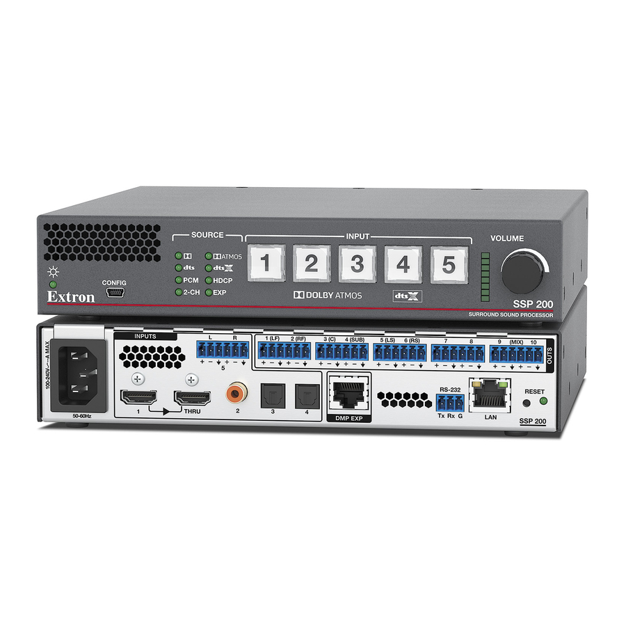
Page 14: Panel Features
4(SUB) 5(LS) 6(RS) (MIX) configurable (see Input/Output Config on page 32). • Input 2 accepts digital signals through a S/PDIF coaxial cable. • Inputs 3 and 4 accept digital signals through S/PDIF optical (TOSLINK) cables. SSP 200 • Panel Features RS-232... - Page 15 (see Product Configuration Software starting on page 29 and SIS Configuration and Control starting on page 62) REMOTE RS-232 RS-232 Device Bidirectional Transmit (Tx) Transmit (Tx) Receive (Rx) Receive (Rx) Ground(Gnd) Ground(Gnd) Figure 6. RS-232 Wiring Example SSP 200 • Panel Features...
- Page 16 INPUT LAN port — RJ‑45 connector allows the SSP 200 to be connected to a Local Area Network (LAN) connection for control and configuration. As with the RS‑232 and USB connections, the device can be controlled using SIS commands through an external control system or via PCS in order to configure the device and receive status information as required.
- Page 17 For unbalanced audio, connect the sleeves to the ground contact. DO NOT connect the sleeves to the negative (–) contacts. • Pour l’audio asymétrique, connectez les manchons au contact au sol. Ne PAS connecter les manchons aux contacts négatifs (–). SSP 200 • Panel Features...
-
Page 18: Securing An Hdmi Connector
Loosely place the included tie wrap around the HDMI connector and the LockIt lacing bracket as shown. While holding the connector securely against the lacing bracket, tighten the tie wrap, then remove any excess length. SSP 200 • Panel Features... -
Page 19: Front Panel Features
5(LS) 6(RS) (MIX) Input Source format indicators Status LED — This LED indicates the current power and boot status of the SSP 200. RESET RS-232 Configuration port — The SSP 200 can be configured via PCS or by using Extron THRU... -
Page 20: Input Selection
Input 1 accepts digital signals through an HDMI cable. • Input 2 accepts digital signals through a S/PDIF coaxial cable. • Inputs 3 and 4 accepts digital signals through S/PDIF optical cables. The SSP 200 supports TOSLINK or TOSLINK‑compatible optical connectors that conform to IEC‑958, S/PDIF standards. INPUTS All four digital inputs accept 16‑... -
Page 21: Volume Adjustment
When the Input 5 button is released, the input gain level control is deactivated. All active (input level) LEDs in the LED array bar deactivate momentarily, and then re‑activate to display the current volume setting. SSP 200 • Panel Features... -
Page 22: System Reset
SSP 200 settings to their defaults. For different reset levels, press and hold the button while the SSP 200 is running. Use a pointed stylus or small screwdriver (such as an Extron Tweeker) to press the button. -
Page 23: Front Panel Security Lockout (Executive Mode)
Mode 3 — All front controls are locked, except for input selection buttons. This feature can only be set using SIS commands (see SIS Configuration and Control page 62) or PCS (see Front Panel Lockout (Executive Mode) on page 52). SSP 200 • Panel Features... -
Page 24: Connecting To The Usb Port
The first screen offers to connect to Windows Update to search the web for the appropriate driver needed for the USB port to communicate with the SSP 200. This is not necessary if the USB driver is already on your PC. - Page 25 When the Completed screen appears, click Finish to close the wizard. NOTE: The wizard opens only on the first occasion you connect the SSP 200 to that USB port. The wizard reappears if you connect the unit to a different USB port or if you connect a different piece of equipment, requiring a different driver, to the same USB port.
-
Page 26: Speaker Setup
Left Height Back Left Back Right Height Back NOTE: All speakers should be angled inwards so that they face towards the listener. 0° 22° 22° 30° 30° 110° 110° 120° 120° Figure 17. Speaker 5.1 Setup SSP 200 • Speaker Setup... - Page 27 125° 0° 22° 22° 30° 30° 150° 30° 90° 90° 110° 110° Figure 19. Speaker 5.1.4 Setup 0° 22° 22° 30° 30° 90° 90° 110° 110° 135° 135° 150° 150° Figure 20. Speaker 7.1 Setup SSP 200 • Speaker Setup...
- Page 28 • The output channel used for the Left Back speaker in 7.1 configurations is also used for the Center Back speaker in 6.1 configurations. SSP 200 • Speaker Setup...
-
Page 29: Back Speakers
Mangement in addition to the LFE signal from the input source. If the subwoofer is disabled, the LFE signal is mixed with the bass information of all speakers in the system that are set to Large, except the center speaker. SSP 200 • Speaker Setup... -
Page 30: Speaker Delay Settings
SSP 200 analog input used as the active input. Signal generators are usually used to test specific decoding mode outputs. When the Active Input option is chosen, the speakers that receive the test signal can be specified. SSP 200 • Speaker Setup... -
Page 31: Output Channel Trim Settings
Listening Mode Settings The SSP 200 provides multiple output mode options for each supported input audio format. By default, the device selects the most appropriate output mode based upon the channel content of the input format and available output channels. This is referred to as Auto Mode. -
Page 32: Reference
HDMI only Master Audio DTS Express HDMI, Coax, Optical DTS:X 7.1.4 HDMI only NOTE: The SSP 200 down mixes any format to match the configuration if the speaker configuration has fewer channels than discrete audio channels. SSP 200 • Reference... -
Page 33: Dolby Digital Source Formats
Digital supports up to six discrete audio channels; five full range front and surround channels and a band‑limited LFE (Low frequency effects) subwoofer channel. Most legacy Dolby Digital formats are supported by the SSP 200 including ProLogic (I & II), EX, and 2.0. Dolby Digital formats are 16‑bit with up to 48 kHz sampling. -
Page 34: Pcm Digital Source Format (Pcm)
When this input is selected, the front panel 2-CH LED is active. Digital These include inputs 1 to 4 only. When the SSP 200 detects any two channel digital signal (including PCM 2‑channel, Dolby Digital 2/0, Dolby Digital 2/0 Surround, or DTS 2‑channel) the 2-CH LED lights. SSP 200 • Reference... -
Page 35: Sampling Frequency
Listening Mode Options and Usage Listening Mode Options The SSP 200 listening modes allow users to upmix or downmix audio content to match their speaker configuration. By default, all listening modes are set to Auto. The auto setting maximizes source formats to the required speaker configuration based on what is available in the room. - Page 36 The Dolby Surround upmixing engine is utilized to upmix input audio to some or all available output channels. DTS Neural:X The DTS Neural:X upmixing engine is utilized to upmix input audio to some or all available output channels. SSP 200 • Reference...
-
Page 37: Product Configuration Software
Product Configuration Software The SSP 200 surround sound processor can be configured using Extron Product Configuration Software (PCS). This section describes: • Downloading PCS from the Extron Website • Using PCS Software • Updating Firmware Using PCS Downloading PCS from the Extron Website Visit www.extron.com... -
Page 38: Using Pcs Software
Devices that are either networked or connected to the PC via USB are listed. Figure 25. PCS Device Discovery Screen Select the SSP 200 device by clicking on it to highlight it in the list ( Click Connect ( The Product Configuration Software opens to the device main menu (see figure 26... -
Page 39: Main Menu
Main Menu NOTE: The SSP 200 tab (top left) has a green indicator, indicating that the deivce connection is live. Figure 26. SSP 200 PCS Main Menu The configuration pages have a global navigation bar from which each of the individual configuration pages can be accessed. -
Page 40: I/O Panel
The fader on the bottom portion is the Main Volume. This sets the volume level for all active speaker outputs of the SSP 200. Below the Main Volume fader is a Mute button that mutes all active speakers (see figure 27). - Page 41 Figure 28. Input/Output Configuration Panel HDMI Input 1 Resolution — Displays the resolution of the HDMI input. HDCP Status — Indicates the HDCP status of the input source. The HDMI input negotiates and authenticates HDCP with the source device if the source requires HDCP encryption.
- Page 42 Output Configuration HDMI Loop Out Audio — Establishes which audio stream is routed to the HDMI Loop Out. The three options are No Audio, Follow Input audio, or the Downmix audio. HDCP Status — Indicates the HDCP status of the output device. The HDMI input negotiates and authenticates HDCP with the sink device, if the sink requires HDCP encryption.
-
Page 43: Edid Minder
EDID Minder EDID Minder manages the EDID information of the HDMI input. Click the EDID Minder tab on the global navigation bar to open the EDID Minder page. This section includes the following: EDID Minder Panels • • EDID Filters •... - Page 44 Figure 32. EDID Favorites Panel • Connected Outputs — Displays the EDID (color‑coded green) of the output connected to the SSP 200 HDMI Thru port (see figure 33). Figure 33. Connected Outputs Panel • Available EDID — Displays the available EDID located on the connected unit or the local PC (see figure 34).
- Page 45 EDID Filters The filters can be used to easily locate specific EDID. Applying a Filter Navigate to the Filters panel on the EDID Minder screen. Select an EDID setting from the drop‑down list of the associated filter. The available EDID that match the filter selection are displayed in the library. Repeat step 2 to apply more filters.
- Page 46 The following pop‑up window displays, indicating that the EDID file was added to your EDID library. Click Close to continue using the software. EDID Assignment The following can be assigned to the inputs of the connected SSP 200: • Extron factory‑default EDID EDID from the display connected to the SSP 200 output port •...
- Page 47 Click Assign. The EDID is assigned to the input and is displayed in the INPUTS panel Alternately, click Assign to All on the INPUTS panel if you would like to assign the same EDID to all inputs. EDID can also be assigned by dragging and dropping the desired EDID directly onto the Inputs panel.
- Page 48 Click Assign. The EDID is assigned to the input and is displayed in the INPUTS panel Alternately, click Assign to All on the INPUTS panel if you would like to assign the same EDID to all inputs. EDID can also be assigned by dragging and dropping the desired EDID directly onto the INPUTS panel.
-
Page 49: Audio Config
Audio Config The Audio Configuration page has four tabs. NOTE: The Audio Configuration tabs should be adjusted in the order they appear. • Speaker Configuration • Speaker Delay Test and Output Trim • • Speaker Equalization/Output EQ Speaker Configuration , on page 31). The Audio Click the Audio Config button (see figure 26, Configuration window opens to the Speaker Configuration panel (see figure 37). - Page 50 Configuration Display — This graphics box shows which speaker channels are active (see figure 37 on the previous page). Only the speakers enabled are displayed. If Full Range is selected for a particular channel then the speaker is represented by a large icon.
- Page 51 Use PCS to set speaker delays, using either of the following methods. Two Person Setup NOTE: Setting up speaker delays is easier with two people. If only one person is available, the position of the ears of the listener must be marked precisely. A pile of boxes could be used to ensure that the distances are consistently measured to the correct height.
- Page 52 Test signals are used during setup to calibrate the level of each channel and to ensure proper connection between the individual output channels of the SSP 200 and the line level input channels of an audio signal processor, a receiver with a built in amplifier, or a stand alone amplifier that powers the loudspeakers.
- Page 53 Signal Type buttons. The Dolby Noise and Pink Noise test signals are generated by the SSP 200. NOTE: If the active input is selected as the test signal, then its listening mode is set to Mono to All when the test sequence is active.
- Page 54 Output Trim The Output Trim sliders control the audio signal level for each individual channel output. Only channels that are enabled in the current speaker configuration are available. Output trim is adjustable from -24 dB to +0 dB. The current value for each output channel is shown in the text box.
- Page 55 All the properties of the SSP 200 parametric filters can be adjusted by the user. The numbers are used to select the filters for utilizing the copy/paste function or to change the focus on the graph to the left.
- Page 56 Filter Parameters These four fields (on the right side of the page) control the parameters that can also be adjusted in the graph. Filter number — Selects a filter to display on the graph or copy and paste functionality. • •...
- Page 57 Figure 44. Center and Outer Handles To modify Q (Parametric filters): In the Filter dialog box, select the filter to be modified. To do so, either click the filter number to the left of Filter menu or click the appropriate Frequency handle below the graph.
-
Page 58: General Settings
General Settings General Settings Click the General Settings button (see figure 26, , on page 31). The General Settings panel (see figure 46) allows you to adjust: • Dolby Settings • DTS Settings Dynamic Range Compression • • Mono Settings • Front Panel Lockout (Executive Mode) The General Settings panel also allows you to access: •... - Page 59 Dolby TrueHD streams. Mono Settings This setting determines how the SSP 200 outputs its mono channels when a mono listening mode is selected, either the center channel or both the front left and right only. SSP 200 • Product Configuration Software...
- Page 60 Front Panel Lockout (Executive Mode) This setting determines what functionality is available on the front of the device. • Unlock Front Panel — Allows all of the buttons to operate normally. Mode 1 — Removes the functionality of every button on the front of the device. •...
- Page 61 The Device Name panel allows you to assign or change the name or hostname of the connected device (see figure 48). Figure 48. Hardware Settings: Device Name NOTE: The device name is used as the hostname of the SSP 200. SSP 200 • Product Configuration Software...
- Page 62 To assign or change the hostname: Enter a name for the device in the name field (see figure 48, , on the previous page). This name can be up to 63 characters in length with no spaces between characters. Only alphanumeric characters and the hyphen are valid. The first character must be alphabetical, and the last one cannot be a hyphen (–).
- Page 63 • The factory configured passwords for all accounts on this device have been set to the device serial number. Passwords are case sensitive. If the SSP 200 is reset, the passwords revert to the default, which is extron. To create or change an administrator password: In the Administrator Password field ( ), enter the desired administrator password.
- Page 64 Hardware Settings panel. The Use DHCP check box ( ) directs the SSP 200 to ignore any entered IP addresses and obtain an IP address from a Dynamic Host Configuration Protocol (DHCP) server (if the network is DHCP capable). Contact the local system administrator to determine if this is the appropriate selection.
-
Page 65: Device Menu
Device Menu The Device menu (see the image on the right) allows the user to: Disconnect the device from PCS. Open the Hardware Settings Communication Settings. Reset Device to factory default. Update Firmware. View the SSP-200 Help file. View information About this Module. Reset Device This function resets all device settings to factory defaults with or without retaining the TCP/ IP settings. -
Page 66: Pcs Help File
) and click Extron PCS Help ( Updating Firmware Using PCS Firmware for the SSP 200 can be updated using PCS. Updates to the SSP 200 firmware are made available periodically via the Extron website. You can find out what version of firmware is currently loaded on your SSP 200 by entering the SIS ... -
Page 67: Loading The Firmware To The Ssp 200
Scroll down the page until you locate the firmware for the SSP 200. Click Download. The product download screen opens. Enter the required user login information. An executable (.exe) file downloads to the PC. Run this program to place the firmware on the PC. Make a note of the folder where the firmware file was saved. - Page 68 The Device menu drops down (see figure 57). Click Update Firmware ( ) and then Update Firmware to this Device... ( Figure 57. Update Firmware to this Device The Update Firmware window opens. Click Continue (see figure 58, Figure 58. Update Firmware Window The Update Firmware to this Device window opens.
- Page 69 Click Close. The software returns to the Device Discovery window (see figure 55 on page 59). Select the SSP 200 from the Device Discovery menu. A connection must be re‑established with the device before continuing to use the software. Click Connect, or double‑click the device. The device reconnects to the software.
-
Page 70: Sis Configuration And Control
The SSP 200 can be configured and controlled using SIS commands or internal web pages. Configure and control the SSP 200 remotely via a host computer or other device (such as a control system) by connecting to the rear panel RS‑232 port, LAN port, or the front panel USB Config port of the SSP device. -
Page 71: Ethernet (Lan) Port
SSP 200 are identical to the commands and actions the processor has when communicating with it via RS‑232. By default, Telnet communication on TCP port 23 is disabled on the SSP 200. You can use Telnet by setting the port using Dataviewer (see Connection Options on page 62) with... -
Page 72: Verbose Mode
If the correct password is entered, the unit responds with ] Login Administrator ] or ] Login User ] , depending on the password entered. If passwords are the same for both administrator and user, the unit defaults to administrator privileges. SSP 200 • SIS Configuration and Control... -
Page 73: Error Responses
Baud rate: 300, 600, 1200, 1800, 2400, 3600, 4800, 7200, 9600, 14400, 19200, 28800, 38400, 57600, 115200 (default=9600) = Parity: ven, one, ark, pace [only use the first letter] (default= =None) = Data bits: 7, 8 (default=8) SSP 200 • SIS Configuration and Control... - Page 74 = Input number: 1 to 5. = EXP assignment (HDMI and analog inputs are unavailable for EXP assignment): 0 = EXP off (default) 2 = Input 2 3 = Input 3 4 = Input 4 SSP 200 • SIS Configuration and Control...
- Page 75 1 = Auto: Encrypt as required by input. Continuous trials for HDMI sinks (Default) 2 = Always Encrypt Output. Continuous trials for HDMI sinks X5& = Output channel (channels 7 to 10 change depending on layout and downmix settings): 1 to 10 or 15 to 16. SSP 200 • SIS Configuration and Control...
- Page 76 = Text – up to 64 characters X12! = SNMP Trap target number (1 to 3) X12@ = SNMP Trap version for target (2 or 3) NOTE: Unless otherwise indicated, commands are not case‑sensitive. SSP 200 • SIS Configuration and Control...
-
Page 77: Command And Response Tables
[only use the first letter] (default= =None) X1& 0000 1000 = Data Pacing [specified in milliseconds between bytes]: – (default= ms). For host port(s), this value is ignored – always returns SSP 200 • SIS Configuration and Control... - Page 78 = Date/Time returned in 7 Hex bytes month, day, year, hour minutes, seconds, day of the week (1 begins on Sunday). SSP-200-01-23-4D = Default name: Combination of model‑name and last 3 pairs of MAC address (for example: SSP 200 • SIS Configuration and Control...
- Page 79 Set SSL port map S{port#}PMAP PmapS{port#} Reset SSL port map S443PMAP PmapS00443 Disable SSL port S0PMAP PmapS00000 View SSL port map SPMAP {port#} Set FTP port map F{port#}PMAP PmapF{port#} Reset FTP port map F21PMAP PmapF00021 SSP 200 • SIS Configuration and Control...
- Page 80 = NTP service mode: = Disable = Enable X12) = Text – up to characters X12! = SNMP Trap target number ( X12@ = SNMP Trap version for target ( SSP 200 • SIS Configuration and Control...
- Page 81 {responds with 4-bytes of file-size Retrieve file from user filenameSF flash memory + raw unprocessed data in file} Backup/Restore Box Configuration Save box configuration 1*{config type}XF Cfg1*{config type} (to filesystem) Restore box 0*{config type}XF Cfg0*{config type} configuration SSP 200 • SIS Configuration and Control...
- Page 82 Device control (no SIS) 1*2HSTM Hstm Disable port 1*0HSTM Hstm Query port mode X4)] 1HSTM KEY: = Serial Host‑control port mode: = Device Control (no SIS) = Standard Host control (SIS ‑ default) Disable Port SSP 200 • SIS Configuration and Control...
- Page 83 = Signal not detected = Signal detected = Input HDCP status: = No source is detected = Source is detected with HDCP = Source detected without HDCP = Enable or Disable: = Disable = Enable (default) SSP 200 • SIS Configuration and Control...
- Page 84 X5& 7–10 KEY: = Analog output channel (channels change depending on layout and downmix settings): (see Output Channels Table on page 68 for details). = Audio Mute: = Mute off (default) = Mute on SSP 200 • SIS Configuration and Control...
- Page 85 = Native resolution and refresh rate from currently assigned EDID, for example: EXP Port Get current device X8!] REXPP connection status X8!] ExppR Verbose modes 2/3 KEY: = Connection status: = Not connected = Connected SSP 200 • SIS Configuration and Control...
- Page 86 = Auto (follow source) = Stereo Mono = Stereo to all = Mono to all Dolby Surround (Upmixer) DTS Neural: X (Upmixer) Resets System reset (factory ZXXX default) Absolute reset including ZQQQ IP settings SSP 200 • SIS Configuration and Control...
- Page 87 = Mono to all Dolby Surround (Upmixer) DTS Neural: X (Upmixer) X10( = Volume level: 100% X11! -18 to +24 dB = Analog input gain: X11@ = Clip status: = Off (no clipping) = On (clipping) SSP 200 • SIS Configuration and Control...
-
Page 88: Internal Web Page
Overview of the Internal Web Page The SSP 200 internal web pages provide the software user interface for operating and configuring the SSP 200 via a PC on the same network. This allows you to: • View and edit the device name Set the date and time either manually or to sync with a connected PC •... -
Page 89: Web
Web Page Components The SSP 200 web page (see figure 63) has eight panels: Device Info Outputs Device Status RS-232 Network Settings Roles and Permissions Inputs Firmware Figure 63. Web Page Device Info The Device Info panel shows the current device name, description, part number, and manufacturer. -
Page 90: Device Status
) when done. You see the changes on the Device Status panel if the update has been successful. Click CANCEL ( ) to exit the process without making any changes. Figure 65. Device Status Settings SSP 200 • Internal Web Page... -
Page 91: Network Settings
Network Settings The Network Settings panel shows the current network settings for the SSP 200 (see figure 63 on page 81). To change the settings, click EDIT to access the Network Settings dialog box (see figure 66). Figure 66. Network Settings Dialog Box... -
Page 92: Inputs
). This panel is not user-configurable. The following status symbols may be displayed for the connected output: Symbol Definition The signal is HDCP compliant. The signal is not compliant. No display is connected. No Signal SSP 200 • Internal Web Page... -
Page 93: Roles And Permissions
• • The default admin name is admin and the default user name is user. • An indicator of the current login status is shown on the top right corner of the main screen. SSP 200 • Internal Web Page... -
Page 94: Firmware
On the Firmware panel, click Select File (see figure 69, ). This opens an Explorer window on your PC. Browse to the location of the firmware and select the file (see figure 70). Figure 70. Selecting the Firmware File SSP 200 • Internal Web Page... - Page 95 ). The firmware is uploaded to the connected device. NOTE: The original factory-installed firmware is permanently available on the SSP 200. If the attempted firmware upload fails for any reason, the processor reverts to the factory version. SSP 200 • Internal Web Page...
- Page 96 Extron Warranty Extron warrants this product against defects in materials and workmanship for a period of three years from the date of purchase. In the event of malfunction during the warranty period attributable directly to faulty workmanship and/ or materials, Extron will, at its option, repair or replace said products or components, to whatever extent it shall deem necessary to restore said product to proper operating condition, provided that it is returned within the warranty period, with proof of purchase and description of malfunction to: USA, Canada, South America,...
Need help?
Do you have a question about the SSP 200 and is the answer not in the manual?
Questions and answers