
Related Manuals for Mitsubishi Electric NZ2GFSS2 32D S1


Summary of Contents for Mitsubishi Electric NZ2GFSS2 32D S1
- Page 1 CC-Link IE Field Network Remote I/O Module (With Safety Functions) User's Manual -NZ2GFSS2-32D-S1 -NZ2GFSS2-8D-S1 -NZ2GFSS2-8TE-S1 -NZ2GFSS2-16DTE-S1 -NZ2EXSS2-8TE ‘TRANSLATION OF THE ORIGINAL INSTRUCTIONS’...
-
Page 3: Safety Precautions
SAFETY PRECAUTIONS (Read these precautions before using this product.) Before using this product, please read this manual and the relevant manuals carefully and pay full attention to safety to handle the product correctly. If the equipment is used in a manner not specified by the manufacturer, the protection provided by the equipment may be impaired. - Page 4 [Design Precautions] WARNING ● When the safety remote I/O module detects an error in a module power supply or an external power supply (IO power), or a failure in the module, it turns off the outputs. Configure an external circuit to ensure that the power source of a hazard is shut off by turning off the outputs.
- Page 5 [Design Precautions] CAUTION ● Do not install the control lines or communication cables together with the main circuit lines or power cables. Keep a distance of 100mm or more between them. Failure to do so may result in malfunction due to noise. ●...
- Page 6 [Wiring Precautions] WARNING ● Shut off the external power supply (IO power) used in the system in all phases before installation and wiring. Failure to do so may result in electric shock or cause the module to fail or malfunction. [Wiring Precautions] CAUTION ●...
- Page 7 [Startup and Maintenance Precautions] WARNING ● Do not touch any terminal while power is on. Doing so will cause electric shock or malfunction. ● Shut off the external power supply (IO power) used in the system in all phases before cleaning the module or retightening the terminal block mounting screw.
- Page 8 [Precautions for Using Products] WARNING ● Although MELCO has obtained the certification for Product's compliance to the international safety standards IEC 61508 and ISO 13849-1 from TUV Rheinland, this fact does not guarantee that Product will be free from any malfunction or failure. ●...
-
Page 9: Conditions Of Use For The Product
(2) Mitsubishi Electric prohibits the use of Products with or in any application involving, and Mitsubishi Electric shall not be liable for a default, a liability for defect warranty, a quality assurance, negligence or other tort and a product liability in these applications. -
Page 10: Table Of Contents
CONTENTS SAFETY PRECAUTIONS ..............1 CONDITIONS OF USE FOR THE PRODUCT . - Page 11 Safety input wiring selection function ............85 Safety input response time setting function.
- Page 12 Appendix 5 EMC, Low Voltage, and Machinery Directives......... . . 197 Measures to comply with the EMC Directive .
-
Page 13: Relevant Manuals
System configuration, parameter settings, and online e-Manual [SH-081215ENG] operations of GX Works3 e-Manual refers to the Mitsubishi Electric FA electronic book manuals that can be browsed using a dedicated tool. e-Manual has the following features: • Required information can be cross-searched in multiple manuals. -
Page 14: Terms
TERMS Unless otherwise specified, this manual uses the following terms. Term Description CC-Link IE Field Network A high-speed and large-capacity open field network that is based on Ethernet (1000BASE-T) Cyclic transmission A function by which data are periodically exchanged among stations on the same network using link devices (RX, RY, RWw, and RWr) Dedicated instruction An instruction that simplifies programming for using functions of intelligent function modules... -
Page 15: Chapter 1 Product Lineup
PRODUCT LINEUP Input module Module name Input specifications Module power Weight Model Reference supply current DC input module Negative Spring clamp terminal block 230mA 0.45kg NZ2GFSS2-32D-S1 Page 20 NZ2GFSS2-32D-S1 common type 24VDC, 32 points type main input module Spring clamp terminal block 150mA 0.25kg NZ2GFSS2-8D-S1... - Page 16 MEMO 1 PRODUCT LINEUP...
-
Page 17: Chapter 2 Part Names
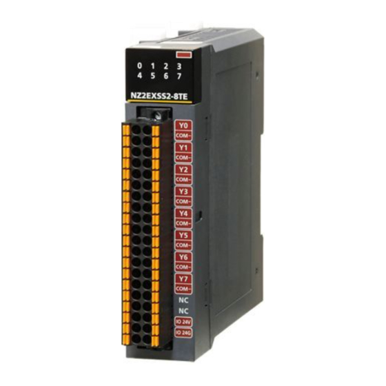
PART NAMES This chapter describes the part names of the safety remote I/O module. Main module ■NZ2GFSS2-32D-S1 ■NZ2GFSS2-8D-S1, NZ2GFSS2-8TE-S1, NZ2GFSS2-16DTE-S1 (11) 2 PART NAMES... - Page 18 Extension module ■NZ2EXSS2-8TE (10) Name Description PW LED Indicates the power supply status. On: Power supply ON Off: Power supply OFF RUN LED Indicates the operating status. On: Operating normally, in initial processing Off: A major error has occurred. MODE LED Indicates the mode status.
- Page 19 Name Description Ethernet port (P1) PORT1 connector for CC-Link IE Field Network (RJ45 connector) Connect an Ethernet cable. For the wiring method and wiring precautions, refer to the following. Page 60 Wiring of Ethernet cable L ER LED Indicates the port status. On: Abnormal data was received or loopback is being performed.
- Page 20 Safety remote I/O module status and LED status The following table lists the correspondence between the safety remote I/O module status and the LED status. For the status of the safety remote I/O module, refer to the following. Page 42 Operation mode and state transition For details on each error, refer to the following.
-
Page 21: Chapter 3 Specifications
SPECIFICATIONS This chapter describes the general specifications, performance specifications of each module, and function list. General Specifications Item Specifications Operating ambient 0 to 55 temperature Storage ambient -40 to 75 temperature Operating ambient 5 to 95%RH, non-condensing humidity Storage ambient humidity 5 to 95%RH, non-condensing Vibration resistance Compliant with JIS B 3502... -
Page 22: Performance Specifications
Performance Specifications NZ2GFSS2-32D-S1 type main input module Item NZ2GFSS2-32D-S1 CC-Link IE station type Remote device station Number of input points Single wiring: 32 points, double wiring: 16 points Rated input voltage 24VDC (ripple ratio: 5% or less) (allowable voltage range: 20.4 to 28.8VDC) Rated input current 6.0mA TYP. - Page 23 Item NZ2GFSS2-32D-S1 Module power supply Voltage 24VDC (ripple ratio: 5% or less) (allowable voltage range: 20.4 to 28.8VDC) Current 230mA Protection function Module power supply overvoltage protection function, module power supply overcurrent protection function Fuse 1.6A (user-unchangeable) Allowable momentary power failure Within 10ms time Weight...
- Page 24 ■External connection Module power supply and FG Pin number Signal name 24VDC +24V +24V +24V I/O terminal block Reverse IO24V connection 5VDC protection circuit 24VDC IO24V Voltage IO24G conversion IO24G circuit Safety switch Internal circuit A device such as safety sensor 24VDC Control 24V IN...
- Page 25 ■Terminal block and signal name Pin number Signal name Pin number Signal name Pin number Signal name Pin number Signal name COM+ COM+ COM+ COM+ COM+ COM+ COM+ COM+ IO24V IO24V IO24G IO24G COM- COM- Among the terminals with the same signal name, you can choose any terminals since they are internally connected. In addition, NC is reserved.
- Page 26 NZ2GFSS2-8D-S1 type main input module Item NZ2GFSS2-8D-S1 CC-Link IE station type Remote device station Number of input points Single wiring: 8 points, double wiring: 4 points Rated input voltage 24VDC (ripple ratio: 5% or less) (allowable voltage range: 20.4 to 28.8VDC) Rated input current 7.0mA TYP.
- Page 27 *1 Only one wire can be connected to a terminal of the terminal block for module power supply and FG. Multiple wires cannot be connected to a terminal. Connecting two or more wires may cause a poor contact. *2 For the power supply to be connected to the main module or the power supply of the devices to be connected to the input part, use the product that meets the following conditions: ...
- Page 28 ■Terminal block and signal name Pin number Signal name Pin number Signal name COM+ COM+ COM- COM- COM- COM- COM- COM- COM- COM- COM- COM- IO24V IO24V IO24G IO24G Among the terminals with the same signal name, you can choose any terminals since they are internally connected. In addition, NC is reserved.
- Page 29 NZ2GFSS2-8TE-S1 type main output module Item NZ2GFSS2-8TE-S1 CC-Link IE station type Remote device station Number of output points Single wiring: 8 points, double wiring: 4 points Rated load voltage 24VDC (ripple ratio: 5% or less) (allowable voltage range: 20.4 to 28.8VDC) Maximum load current 0.5A/point Isolation method...
- Page 30 *1 Only one wire can be connected to a terminal of the terminal block for module power supply and FG. Multiple wires cannot be connected to a terminal. Connecting two or more wires may cause a poor contact. *2 To connect to the main module, use the power supply that meets the following conditions: ...
- Page 31 ■Terminal block and signal name Pin number Signal name Pin number Signal name COM+ COM+ COM- COM- COM- COM- COM- COM- COM- COM- COM- COM- IO24V IO24V IO24G IO24G Among the terminals with the same signal name, you can choose any terminals since they are internally connected. In addition, NC is reserved.
- Page 32 NZ2GFSS2-16DTE-S1 type main I/O combined module Item NZ2GFSS2-16DTE-S1 CC-Link IE station type Remote device station Number of input points Single wiring: 8 points, double wiring: 4 points Rated input voltage 24VDC (ripple ratio: 5% or less) (allowable voltage range: 20.4 to 28.8VDC) Rated input current 7.0mA TYP.
- Page 33 Item NZ2GFSS2-16DTE-S1 Cyclic transmission RX/RY points 80 points RWr/RWw points 32 points SA\X/SA\Y points 32 points Applicable safety protocol version 2 (fixed) Communication cable An Ethernet cable that meets the 1000BASE-T standard: Category 5e or higher (double shielded, STP), straight cable Availability of connecting extension module Connectable *2*4...
- Page 34 ■External connection Terminal block for module power supply and FG Pin No. Signal name 24VDC +24V +24V I/O terminal block Reverse +24V IO24V connection protection circuit 24VDC IO24V IO24G IO24G Safety switch A device such as safety sensor 24VDC Control 24V IN output 1 Control...
- Page 35 ■Terminal block and signal name Pin number Signal name Pin number Signal name COM+ COM+ COM- COM- COM- COM- COM- COM- COM- COM- COM- COM- IO24V IO24V IO24G IO24G Among the terminals with the same signal name, you can choose any terminals since they are internally connected. In addition, NC is reserved.
- Page 36 NZ2EXSS2-8TE type extension output module Item NZ2EXSS2-8TE Number of output points Single wiring: 8 points, double wiring: 4 points Rated load voltage 24VDC (ripple ratio: 5% or less) (allowable voltage range: 20.4 to 28.8VDC) Maximum load current 0.5A/point 4A/common (horizontal installation), when any installation method other than the horizontal installation is performed, refer to the derating chart.
- Page 37 ■Derating chart (except horizontal installation) Common current (A/common) Ambient temperature (°C) ■External connection I/O terminal block +24V Reverse connection IO24V protection 5VDC IO24V 24VDC circuit Voltage IO24G conversion IO24G circuit Safety relay Load Safety relay Internal circuit COM- COM- COM- 3 SPECIFICATIONS 3.2 Performance Specifications...
- Page 38 ■Terminal block and signal name (A) I/O terminal block Signal Signal number name number name COM- COM- COM- COM- COM- COM- COM- COM- COM- COM- COM- COM- COM- COM- COM- COM- IO24V IO24V IO24G IO24G Among the terminals with the same signal name, you can choose any terminals since they are internally connected. In addition, NC is reserved.
- Page 39 The safety response time of the safety remote I/O module is shown below. For the response time including the network delay time, refer to the following. Mitsubishi Electric Safety Programmable Controller MELSEC iQ-R Series Machinery Directive (2006/42/EC) Compliance ■Input Transmission interval monitoring time ...
- Page 40 Calculating current consumption To supply power to multiple modules with the transition wiring, configure the system so that the current consumption does not exceed the maximum rated current. The following shows how to calculate the current consumption using the system configuration shown below as an example.
- Page 41 ■Calculating the current consumption of each power supply port Use each current consumption in the system and the current value of the maximum rated current in the system for the calculation and check that the current consumption does not exceed the maximum rated current. •...
-
Page 42: Function List
Function List This section describes the function list, operation modes, and state transition. Function list : Available, : Not available Item Description Availability Reference NZ2GFSS2- NZ2GFSS2- NZ2GFSS2- NZ2GFSS2- 32D-S1 8D-S1 8TE-S1 16DTE-S1 Safety input wiring Selects double wiring or single wiring of Page 85 Safety input selection function the input wiring. - Page 43 The safety remote I/O module does not support the CC-Link IE Field Network synchronous communication function. 3 SPECIFICATIONS 3.3 Function List...
- Page 44 Operation mode and state transition The following describes the state transition and transition conditions of the safety remote I/O module. (1) Power supply OFF state (2) Initial processing state (3) Unit test mode (6) Moderate error status (4) Standby mode (7) Major error status (5) Safety operation mode *1 When a moderate error or major error has occurred, the state is changed into an error state.
-
Page 45: Chapter 4 Procedures Before Operation
PROCEDURES BEFORE OPERATION Procedures Before Operation Consideration of system configuration Complete the following items prior to the module installation. Determine a safety category required for configuring the safety system. Determine function wiring required for configuring the safety system. Determine the network number and station number of the safety remote I/O module. Module installation, wiring, and parameter setting Mounting the module Mount the safety remote I/O module on the panel surface or a DIN rail. -
Page 46: Module Replacement Procedure
Module Replacement Procedure Preparation for module replacement Complete the following items prior to the module replacement. Checking operations of a new module Perform the unit test of the new safety remote I/O module. Page 126 Unit Test Setting station numbers of the new module Set station numbers of the new safety remote I/O module. -
Page 47: Chapter 5 System Configuration
SYSTEM CONFIGURATION This chapter describes the system configuration using a safety remote I/O module. For CC-Link IE Field Network configuration, refer to the following. MELSEC iQ-R Ethernet/CC-Link IE User's Manual (Startup) Safety Remote I/O Module System Configuration The following shows system configurations using safety remote I/O modules. For the NZ2GFSS2-32D-S1 (1) Main module (2) Safety extension module... -
Page 48: Applicable Systems
Applicable Systems Applicable products When using a safety remote I/O module, use the following products. For the model of the Safety CPU and safety function module, refer to the following. MELSEC iQ-R Module Configuration Manual Module Firmware version Safety CPU 29 or later Safety function module 29 or later... -
Page 49: Safety Standards
Safety Standards This product complies with the following standards. Standard EN ISO 13849-1: 2015 EN ISO 13849-2: 2012 EN 61508 Parts 1-7: 2010 EN 61131-2: 2007 (clauses 6.1-6.3, 8) IEC 61131-2: 2017 (clauses 5.2.1, 5.3, 7) EN 61000-6-7: 2015 The revisions of the standards are subject to update. For the latest information, visit the TUV Rheinland's website (www.tuv.com) and check the EC Type-Examination Certificate. -
Page 50: Chapter 6 Installation And Wiring
INSTALLATION AND WIRING This chapter describes the installation and wiring. Setting of Network Number and Station Number Set the network number and station number to the safety remote I/O module. To set the network number, use the engineering tool. To set the station number, use the rotary switch on the front of the module. For the setting of the network number, refer to the following. -
Page 51: Installation Environment And Installation Position
Installation Environment and Installation Position Installation environment Installation location Do not install the safety remote I/O module to the place where: • Ambient temperature is outside the range of 0 to 55; • Ambient humidity is outside the range from 5 to 95% RH; •... -
Page 52: Installation Direction
Installation direction The safety remote I/O module can be installed in six directions. Use the DIN rail to install the module. Downward installation DIN rail Horizontal installation Vertical installation Horizontal installation (upside down) Upward installation The figure above shows the examples for the NZ2GFSS2-32D-S1 and NZ2EXSS2-8TE. The installation directions other than the horizontal installation have restrictions on the maximum number of simultaneous input points and maximum load current. -
Page 53: Installation
Installation Installation of extension modules The numbers of input points and output points can be increased by connecting extension modules. Number of extension modules connectable to a main module Module model name Model name of connectable extension modules Number of connectable extension modules NZ2GFSS2-32D-S1 NZ2EXSS2-8TE •... - Page 54 Insert the connector of the extension module into that of the main module so that they are securely engaged. Do not tilt the extension module when inserting the connector. Lock the module joint levers (four points) on the side of the extension module.
- Page 55 Lock the module joint levers (two points) on the side of Lock the extension module. Slide the levers toward the module. Check that the extension module is securely connected after locking the levers. Lock ■Precautions Lock the module joint levers securely. Failure to do so may cause malfunction, failure, or drop of the module. Removal procedure Disconnect the extension module by reversing the connection procedure.
-
Page 56: Mounting The Module On A Din Rail
Mounting the module on a DIN rail The following procedure is just an example of fixing the module with a DIN rail stopper. When fixing the module, refer to the manual of the DIN rail stopper used. Installation procedure Pull down all DIN rail hooks on the back of the module. The hooks should be pulled down until they click. - Page 57 Hitch the upper hook of the DIN rail stopper to the top of Hitch the hook to the DIN rail. top of the DIN rail Slide the DIN rail stopper up to the left side of the DIN rail module. stopper Hold the DIN rail stopper in the direction opposite to the DIN rail...
- Page 58 Removal procedure Remove the module from the DIN rail by reversing the installation procedure. Applicable DIN rail model (compliant with JIS C 2812/IEC 60715) • TH35-7.5Fe • TH35-7.5Al Interval between DIN rail mounting screws Tighten the screws at intervals of 200mm or less. DIN rail stopper Use a stopper that is attachable to the DIN rail.
-
Page 59: Wiring
Wiring Wiring of terminal block for module power supply and FG Tightening torque Tighten the terminal block mounting screws within the following specified torque range. Tightening the screws too much may damage the module case. Screw type Tightening torque range Terminal block mounting screw (M2.5 screw) 0.2 to 0.3Nm Wire to be used... - Page 60 Connecting a cable To connect a cable, push the open/close button with a flathead screwdriver, insert the wire into the wire insertion opening, and remove the screwdriver. When using a bar solderless terminal, insert the wire with a bar solderless terminal into the wire insertion opening and push it in.
- Page 61 List of bar solderless terminals When using a bar solderless terminal, the products listed below are recommended. For a processing method of the cable terminal, such as the stripping length of the cable, follow the specifications of the terminal used. Use UL listed bar solderless terminals, and for processing, use a tool recommended by manufacturers of solderless terminals.
-
Page 62: Wiring Of Ethernet Cable
Wiring of Ethernet cable Connecting the Ethernet cable ■Connecting Power off the module power supply of the safety remote I/O module and the power supply of the external device. Push the Ethernet cable connector into the safety remote I/O module until it clicks. Pay attention to the connector's direction. - Page 63 • PORT1 and PORT2 need not to be distinguished. When only one connector is used in star topology, either PORT1 or PORT2 can be connected. Either one can be used. • When two connectors are used in line topology or ring topology, an Ethernet cable can be connected to the connectors in any combination.
- Page 64 Precautions ■Laying Ethernet cables • Place the Ethernet cable in a duct or clamp it. If not, dangling cable may swing or inadvertently be pulled, resulting in damage to the module or cables or malfunction due to poor contact. • Do not touch the core of the connector of the cable or the module, and protect it from dirt and dust. If any oil from your hand, or any dirt or dust sticks to the core, it can increase transmission loss, causing data link to fail.
-
Page 65: Wiring Of Terminal Block For The External Power Supply And I/O Signals
Wiring of terminal block for the external power supply and I/O signals Tightening torque Tighten the terminal block mounting screws within the following specified torque range. Tightening the screws too much may damage the module case. Screw type Tightening torque range Terminal block mounting screw (M2 screw) 0.1 to 0.2Nm Wire to be used... - Page 66 ■Installation procedure Install the terminal block. Tighten the terminal block mounting screws. Securely install the terminal block with the terminal block mounting screws. Failure to secure the terminal block Terminal block may cause drop, short circuit, malfunction. mounting screw Connecting a cable To connect a cable, push the open/close button with a flathead screwdriver, insert the wire into the wire insertion opening, and remove the screwdriver.
- Page 67 Processing method of the cable terminal • When using a stranded wire, strip the cable 10mm from the tip. Stripping the cable too long may cause electric shock or short circuit between adjacent terminals because the conductive part sticks out of the terminal block. Stripping the cable too short may cause a poor contact to the spring clamp terminal part.
-
Page 68: Precautions For Wiring The Safety Remote I/O Module To Safety Devices
Precautions for wiring the safety remote I/O module to safety devices This section describes the precautions for the wiring. To wire the safety remote I/O module to each safety device according to Category 4, perform both of the following for the safety remote I/O module. •... - Page 69 Wiring of the external power supply If the external power supply is off when the module power supply is turned on, a moderate error or minor error (external power supply voltage error) occurs. Power on the external power supply at the same timing of power-on of the module power supply. 6 INSTALLATION AND WIRING 6.4 Wiring...
-
Page 70: Chapter 7 Various Settings
VARIOUS SETTINGS Overview of the parameter setting procedure Preparation Perform the following before parameter settings. • Configure the system. • Start the engineering tool. • Set the Safety CPU to the test mode. For details on the test mode of the Safety CPU, refer to the following. ... -
Page 71: Network Configuration Settings
Network Configuration Settings The following parameters are required to use the safety remote I/O module. The parameters are automatically set when a main module is added in the "Network Configuration Settings". Change the start number and end number of the RX/RY Setting or RWr/RWw Setting as necessary. - Page 72 Setting procedure The following shows the procedure to set module parameters of the master station from the "Network Configuration Settings" window. When the user authentication function of the CPU module is enabled, perform the logon of the user authentication function in advance. For the user authentication function, refer to the following. Page 109 User Authentication Function Operating procedure For preparation before setting module parameters, follow the steps below.
- Page 73 Drag and drop the icon of the main module from "Module List" to the lower window. At this time, "STA#", "Station Type", "RX/RY Setting", and "RWw/RWr Setting" are automatically input. Change a value as necessary. To use an extension module, drag and drop the icon of the extension module from "Module List" to the right side of the main module icon. Close the "CC IE Field Configuration"...
-
Page 74: Parameter Settings
Parameter Settings This section shows lists of the module parameters of the safety remote I/O module. The following parameters cannot be set from a program. Window 7 VARIOUS SETTINGS 7.2 Parameter Settings... - Page 75 Parameter list ■NZ2GFSS2-32D-S1 Item Setting range Reference Station parameter Transmission interval monitoring time 4 to 1000ms (default: 35) Page 37 Safety remote I/O module safety response time Operation setting of external power supply voltage error detection 0: Stop safety communication Page 110 Operation Setting (default) Function at Detection of...
- Page 76 ■NZ2GFSS2-8D-S1 Unit Item Setting range Reference Station parameter Safety setting Transmission interval monitoring 4 to 1000ms (default: 35) Page 37 Safety remote I/O time module safety response time I/O LED indication setting at error occurrence 0: No indication of error point (default) 1: Indication of error point 0 to 20 (default: 0) ...
- Page 77 ■NZ2GFSS2-8TE-S1 Unit Item Setting range Reference Station parameter Safety setting Transmission interval monitoring 4 to 1000ms (default: 35) Page 37 Safety remote I/O time module safety response time I/O LED indication setting at error occurrence 0: No indication of error point (default) 1: Indication of error point 0 to 20 (default: 0) ...
- Page 78 ■NZ2GFSS2-16DTE-S1 Unit Item Setting range Reference Station parameter Safety setting Transmission interval monitoring 4 to 1000ms (default: 35) Page 37 Safety remote I/O time module safety response time I/O LED indication setting at error occurrence 0: No indication of error point (default) 1: Indication of error point 0 to 20 (default: 0) ...
- Page 79 Unit Item Setting range Reference Basic module Wiring selection of input Wiring selection of input X0 to Wiring 0: Not used (default) Page 85 Safety input wiring parameter_main selection of input X7 1: Double wiring (NC/NC) selection function module 2: Single wiring Input response time [main Input response time X0 to Input 0: 1.0ms (default)
- Page 80 Parameter setting procedure The following shows the procedure to set module parameters of the safety remote I/O module from the "Network Configuration Settings" window. When the user authentication function of the CPU module is enabled, perform the logon of the user authentication function in advance.
- Page 81 Set "Method selection" to "Parameter write" so that a value can be set in an item of "Write Value". Set values in all the items of "Write Value". If an item where a value is not set exists, the parameters cannot be written. For the module parameter list for the safety remote I/O module, refer to the following.
- Page 82 After writing parameters is completed, visually check that the module parameters have been normally written to the module. To check the module parameters, refer to the following. GX Works3 Operating Manual Perform the operations from "Parameter write" to the visual check of the module parameters for all safety remote I/O modules connected.
- Page 83 Select "Local Network" in "Communication Destination" and the "Select the target module for the Safety Communication Setting" window is displayed. Select the target safety remote I/O module and click the [Add] button. The parameters of the safety remote I/O module selected on the "Select the target module for the Safety Communication Setting"...
- Page 84 When parameter writing to the programmable controller is completed, select the target safety remote I/O module in the "Network Configuration Settings" and display the "Command Execution of Device Station" window. [Network Configuration Settings] Select the target main module. [CC IE Field Configuration] [Online] [Command Execution of Device Station] Select "Start of checking the module position"...
- Page 85 Perform the operations from "Start of checking the module position" to "Stop of checking the module position" for all safety remote I/O modules connected. Select "Safety module validation" in "Method selection" and click the [Execute] button. Clicking the [Execute] button displays the following confirmation window. Check the contents, and if the operations mentioned on the window are completed, click the [Yes] button.
-
Page 86: Chapter 8 Functions
FUNCTIONS This chapter describes the functions available in the safety remote I/O module, and the setting procedures for those functions. For details on safety remote I/O signals, remote control/monitor signals, and remote buffer memory, refer to the following. • Page 158 Safety Remote I/O Signals •... -
Page 87: Safety Input Function
Safety Input Function This function safely inputs external signals. This function cannot be used in any modes other than the safety operation mode. All the safety remote inputs (SA\X) are off in any modes other than the safety operation mode. Safety input wiring selection function This function is used to select double wiring or single wiring of the input wiring. - Page 88 Single wiring function This function can connect input devices with single wiring. Safety remote I/O module • To satisfy SIL3, Category 4 and PL e, use the double wiring function. • Systems using single wiring do not comply with SIL3 or Category 4 PL e, although the wiring can be used for input using safety devices.
- Page 89 ■States of safety remote inputs (SA\X0, SA\X1) for X0 and X1 (double wiring) Double input discrepancy detection state Input terminal status: X0 Input terminal status: X1 SA\X0 SA\X1 (1) Even when the input terminal X0 turns on, SA\X0 does not turn on because X1 is off. (2) When the double inputs are on (X0 and X1 are on), SA\X0 and SA\X1 turn on.
-
Page 90: Safety Input Response Time Setting Function
Safety input response time setting function The safety input response time setting function is used to set the filter time to reduce incorrect inputs caused by noise in input signals. The longer the input response time is, the higher tolerance for chattering and noise the module has. But the response to input signals becomes slower. -
Page 91: Safety Output Function
Safety Output Function This function safely outputs signals. This function cannot be used in any modes other than the safety operation mode. All the safety remote outputs (SA\Y) are off in any modes other than the safety operation mode. Safety output wiring selection function This function is used to select double wiring or single wiring of the output wiring. - Page 92 Single wiring function This function can connect output devices with single wiring. IO24V Load External power supply Safety remote I/O module IO24G COM- • To satisfy SIL3, Category 4 and PL e, use the double wiring function. • Systems using single wiring do not comply with SIL3 or Category 4 PL e, although the wiring can be used for output using safety devices.
- Page 93 Combination of double outputs Both terminals of double outputs are turned on only when both safety remote outputs (SA\Y) are on. The safety remote I/O module evaluates the logic of safety remote outputs (SA\Y) and determines the state of the output terminals. The following table lists the correspondence between each state of safety remote output (SA\Y) and output terminal for double outputs.
-
Page 94: Number Of Safety Output On Times Integration Function
Number of safety output ON times integration function This function counts the number of ON times of each output point within the range of 0 to 2147483647. The integration value remains even though the output module is powered off. Whether to enable or disable the function can be set for each output point from the module parameter setting window of the engineering tool or the program. -
Page 95: Input Diagnostic Function
Input Diagnostic Function Double input discrepancy detection function This function discriminates failures by monitoring the discrepancy state of doubled safety remote inputs (SA\X). Double input discrepancy detection ■Double input discrepancy detection (with discrepancy detection time specified) If "Double input discrepancy detection setting" is set to "0: Detect" and "Double input discrepancy detection type" is set to "0: Discrepancy detection time specified"... - Page 96 ■Double input discrepancy detection (with discrepancy detection time not specified) When "Double input discrepancy detection setting" is set to "0: Detect" and "Double input discrepancy detection type" is set to "1: Discrepancy detection time not specified" from the "Parameter Processing of Device Station" window, no input error occurs even though the discrepancy state of double inputs continues.
- Page 97 • When a double input discrepancy detection error occurs When the discrepancy (ON/OFF or OFF/ON) state of input terminals continues for longer than 500ms after changed from ON/ ON state, the double input discrepancy is detected and the double input discrepancy detection state is applied. The error (double input discrepancy detection error) does not occur.
- Page 98 ■Application and example of double input discrepancy detection (with discrepancy detection time not specified) When a certain double input discrepancy detection time cannot be applied for the application, this function is used. Even if a double input discrepancy is detected, a double input discrepancy detection error does not occur immediately. The error occurs only when certain conditions are satisfied.
- Page 99 ■Setting method Configure the double input discrepancy detection setting in "Double input discrepancy detection setting" and "Double input discrepancy detection type" from the "Parameter Processing of Device Station" window of the engineering tool. For the procedure to display the "Parameter Processing of Device Station" window, refer to the following. Page 72 Parameter Settings Item Setting range...
- Page 100 ■Setting method Set the double input discrepancy detection time in "Double input discrepancy detection time" from the "Parameter Processing of Device Station" window of the engineering tool. For the procedure to display the "Parameter Processing of Device Station" window, refer to the following. Page 72 Parameter Settings Item Setting range...
- Page 101 Double input discrepancy auto recovery function When a double input discrepancy detection error has occurred, removing the error factor recovers the module into the normal state automatically. By enabling this function, the reset operation of the safety remote I/O module to reset errors is not required.
- Page 102 ■Monitor signal for the double input discrepancy detection state When "Double input discrepancy auto recovery setting" is set to "1: Used", the detection state of a double input discrepancy can be monitored using Double input discrepancy detection state. For details on Double input discrepancy detection state, refer to the following.
-
Page 103: Input Dark Test Function
Input dark test function This function outputs test pulses to turn off the external input signals (X) that are on and diagnoses contacts including external devices for failure. Failures including circuit fixing and short-circuit faults can be detected. The OFF time for test pulses and the number of pulse outputs used in one diagnostic can be set depending on the usage environment. - Page 104 Operation at error detection When an error is detected in a diagnostic of the input dark test, the error (input dark test error) state is applied. For details on the error state, refer to the following. Page 138 Error codes related to the safety remote I/O module •...
- Page 105 Setting method Set the following parameters for the input dark test function. There is a mutual relation of the parameter values of the input response time and input dark test. When setting parameters, set values that meet the mutual relation. For details, refer to the following. Page 88 Relation of the parameters for the input response time and input dark test ■Input dark test execution setting Set whether to perform the input dark test or not in "Input dark test execution setting"...
-
Page 106: Internal Input Dark Test Function
Internal input dark test function This function outputs test pulses to the input circuit of the safety remote I/O module to detect a circuit-fixing failure. The test pulses turn off the external input signals (X0 to X1F) that are on to detect the failure. Test pulse Test pulse Test pulse output circuit... -
Page 107: Output Diagnostic Function
Output Diagnostic Function Output dark test function This function outputs test pulses to turn off the external output signal Y that is on and diagnoses the internal circuit for failure. The read-back circuit checks the test pulse and output circuit fixing can be detected. The OFF time for test pulses and the number of pulse outputs used in one diagnostic can be set depending on the usage environment. - Page 108 Setting method ■Output dark test execution setting Set whether to perform the output dark test or not in "Output dark test execution setting" from the "Parameter Processing of Device Station" window of the engineering tool. For the procedure to display the "Parameter Processing of Device Station" window, refer to the following. Page 72 Parameter Settings Item Setting range...
-
Page 109: Output Read-Back Function
Output read-back function This function reads back output results and diagnoses whether the external output signal Y is correctly on or off. The read- back circuit checks the status of output terminals and diagnoses whether it matches with the output status of the control program to detect output operation errors in the module. -
Page 110: Protection Functions
Protection Functions The following table lists the protection functions. Function name Purpose Description Module power supply overvoltage Prevents ignition or burnouts from/of the safety remote I/O This function operates when the module power supply is in protection module due to overvoltage on the primary side. the overvoltage state. -
Page 111: User Authentication Function
User Authentication Function This function limits the users (persons and personal computers) that can access the CPU module or safety remote I/O module. Using this function permits only the specified users to access the CPU module or safety remote I/O module. This function is implemented in the CPU module used. -
Page 112: Operation Setting Function At Detection Of External Power Supply Voltage Error
Operation Setting Function at Detection of External Power Supply Voltage Error Users can select whether to continue safety communication or stop it when an external power supply voltage error occurs. Restoration The following table shows how the module operation will be restored from the external power supply voltage error. Item Restoration Operation at the error... - Page 113 Stop safety communication ■Output interlock After an external power supply voltage error is detected, safety communications stop and the outputs are interlocked. For the NZ2GFSS2-32D-S1 Module operation mode Standby mode Safety operation mode Moderate error state Status of the external power Normal Error supply...
- Page 114 Continue safety communication (Without output interlock) ■Output interlock If safety outputs are turned off due to an external power supply voltage error detection, the outputs are interlocked. If the outputs are interlocked, the safety output control stops and the output signals (Y) are turned off. For the NZ2GFSS2-32D-S1 Module operation mode Standby mode...
- Page 115 ■Output interlock cancellation After causes of an external power supply voltage error are eliminated, the safety output control restarts and safety outputs and test pulse outputs restart. For the NZ2GFSS2-32D-S1 Module operation mode Safety operation mode Status of the external power Error Normal supply...
- Page 116 Continue safety communication (With output interlock) ■Output interlock In the following cases, the outputs are interlocked. • Module operation mode is switched from standby mode to safety operation mode. • Safety outputs are turned off due to an external power supply voltage error detection. If the outputs are interlocked, the safety output control stops and the output signals (Y) are turned off.
- Page 117 ■Output interlock cancellation After causes of the external power supply voltage error are eliminated, the safety output control will start by canceling the output interlock by the CPU module. For the NZ2GFSS2-32D-S1 Operating procedure After checking that External power supply status is on, turn on Safety output control initial processing request flag (SA\Y2E).
- Page 118 <When the module shifts to the safety operation mode> Module operation mode Standby mode Safety operation mode External power supply status Normal <When an external power supply voltage error has occurred> Module operation mode Safety operation mode External power supply status Error Normal External power supply status...
-
Page 119: Functions Available When Extension Modules Are Connected
Functions Available When Extension Modules Are Connected The functions of the safety extension module or the standard extension module are available when the extension module is connected. Functions that can be used when a safety extension module is connected The following lists the functions that can be used when a safety extension module is connected. Function Reference Page 89 Safety Output Function... - Page 120 Functions that can be used when a standard extension module is connected The following lists the functions that can be used when a standard extension module is connected. Item Description Input function Acquires the ON/OFF status of the inputs. Output function Controls the ON/OFF status of the outputs.
-
Page 121: Chapter 9 Maintenance And Inspection
MAINTENANCE AND INSPECTION This chapter describes the maintenance and inspection of the safety remote I/O module. Read [Startup and Maintenance Precautions] in the safety precautions carefully before performing the inspection, and observe the precautions. Daily Inspection The following table lists the items that must be inspected on a daily basis. Item Inspection item Inspection method... - Page 122 Item Inspection item Inspection method Judgment criterion Corrective action LED status in PW LED Check that the LED is on. Refer to the following and take operation corrective actions. RUN LED Check that the LED is on. Page 123 Checking the LEDs MODE LED Check that the LED is on.
-
Page 123: Periodic Inspection
Periodic Inspection This section describes items that must be inspected one or two times every six months to one year. When the equipment has been relocated or modified, or cable laying has been changed, inspect the module for the items. Item Inspection item Inspection method... -
Page 124: Chapter 10 Troubleshooting
TROUBLESHOOTING This chapter describes the troubleshooting of the safety remote I/O module. 10.1 CC-Link IE TSN/CC-Link IE Field Diagnostics For details on CC-Link IE TSN/CC-Link IE Field diagnostics, refer to the following. MELSEC iQ-R CC-Link IE Field Network User's Manual (Application) Remote reset Perform the following operations to reset the selected safety remote I/O module through the remote operation. -
Page 125: Checking The Leds
10.2 Checking the LEDs This section describes how to troubleshoot the system by the LEDs. Depending on an LED status of the RUN LED, ERR. LED, or SAFETY LED, the error status can be judged as follows. RUN LED ERR. LED SAFETY LED Error status Reference on errors... - Page 126 When the I/O PW LED does not turn on Check item Action Is the external power supply turned on? (Only for • Set the external power supply voltage within the range of performance specifications. ( Page 20 the NZ2GFSS2-8D-S1, NZ2GFSS2-8TE-S1, or Performance Specifications) NZ2GFSS2-16DTE-S1) •...
- Page 127 When the I/O LED flashes Check item Action Has any error related to safety I/O occurred when Identify the error factor of the safety remote I/O module with the engineering tool and take corrective "I/O LED indication at error occurrence" is set to actions.
-
Page 128: Unit Test
10.3 Unit Test Run a unit test to check if there is any hardware failure in the safety remote I/O module. Power off the module power supply. Connect the PORT1 and PORT2 connectors of the safety remote I/O module with an Ethernet cable. Ethernet cable Set the station number setting switch as follows. -
Page 129: Troubleshooting By Symptom
10.4 Troubleshooting by Symptom This section describes troubleshooting for each phenomenon. Perform the troubleshooting by symptom when the safety remote I/O module does not operate properly with no error. When an error has occurred in the safety remote I/O module, check the engineering tool or the status of the master station, and identify the cause of the error. - Page 130 When the safety remote I/O module cannot be accessed Check item Action Is the D LINK LED on? Check the D LINK LED. When the LED is not on, refer to the following to perform troubleshooting. • Page 124 When the D LINK LED turns off •...
-
Page 131: Fault Examples With The Safety Remote I/O Module
10.5 Fault Examples with the Safety Remote I/O Module Input circuit troubles and corrective actions An input signal does not turn off. ■Cause Operation by a switch with LED indicator DC input Leakage current (1) Safety remote I/O module ■Action Connect an appropriate resistor as shown below so that the leakage current flowing into the safety remote I/O module would fall below the OFF current. - Page 132 When the resistor (R) is 2.0k, for example, the power capacity (W) of the resistor (R) becomes 0.41W. (Input voltage) 28.8 = 0.41 [W] 2000 [Ω] Because the resistor requires a power capacity that is 3 to 5 times larger than the actual current consumption, the resistor connected to the terminal should be 2.0k;...
-
Page 133: Output Circuit Troubles And Corrective Actions
Output circuit troubles and corrective actions The load in the off state momentarily turns on at power off (transistor output). ■Cause When an inductive load is connected, the load [2] in the off state may turn on due to a sneak current from the back EMF at the shutoff [1]. -
Page 134: How To Check Error Codes
10.6 How to Check Error Codes When the data link is established between the safety remote I/O module and the master station, errors can be checked on the engineering tool. • Page 132 Checking with CC-Link IE TSN/CC-Link IE Field diagnostics •... - Page 135 Right-click on the module selected, and select "Error History" from the menu. Click the [Yes] button. 10 TROUBLESHOOTING 10.6 How to Check Error Codes...
- Page 136 Checking with "Command Execution of Device Station" The following describes how to check errors with "Command Execution of Device Station" in the "Network Configuration Settings". Select the safety remote I/O module in "List of stations" on the "CC IE Field Configuration" window. Open the "Command Execution of Device Station"...
- Page 137 ■For the NZ2GFSS2-32D-S1 Item Description Storage example Error and Solution Error codes and error details of the errors that have occurred are displayed. Error classification The error classifications of safety error subset codes are stored. Error item number The error item numbers of safety error subset codes are stored.
- Page 138 Checking error codes and warning codes The latest error code and warning code of the safety remote I/O module can be checked with the remote register of the master station. ■Checking error codes Check the error codes with the remote register of the master station. [Online] ...
-
Page 139: List Of Error Codes
10.7 List of Error Codes Error classification by error number Error codes are classified by error number as follows. Module model name Error code Classification Reference NZ2GFSS2-32D-S1 0000H to 3FFFH Safety remote I/O module error Page 138 Error codes related to the safety remote I/O module D529H, D52BH D000H to DFFFH CC-Link IE Field Network error... -
Page 140: Error Codes Related To The Safety Remote I/O Module
Error codes related to the safety remote I/O module Errors of the safety remote I/O module are classified into the following three types. Error status Description Major error Error because of which the module stops, such as hardware failure. The safety functions (safety I/O, safety diagnostics, and safety communications) stop. - Page 141 Error code Safety error subset code Classification Error name Description and Action (hexadecimal) cause Error Error item classification number (hexadecimal) 0105H 0105H Moderate error Date out of Incorrect clock data There may be an influence from range error was received from noise or a hardware failure.
- Page 142 Error code Safety error subset code Classification Error name Description and Action (hexadecimal) cause Error Error item classification number (hexadecimal) 0204H 0204H Minor error Double input A double input • Match the ON timing of the Recoverable discrepancy discrepancy was external power supply with the detection error detected in a pair of...
- Page 143 Error code Safety error subset code Classification Error name Description and Action (hexadecimal) cause Error Error item classification number (hexadecimal) 0207H 0207H Minor error Output read- A discrepancy of an • Match the ON timing of the back error output read-back external power supply with the value and an output ON timing of the module power...
- Page 144 Error code Safety error subset code Classification Error name Description and Action (hexadecimal) cause Error Error item classification number (hexadecimal) 020BH 020BH Minor error External power An external power • Match the ON timing of the supply voltage supply error was external power supply with the error detected.
- Page 145 Error code Safety error subset code Classification Error name Description and Action (hexadecimal) cause Error Error item classification number (hexadecimal) 0530H 0530H Moderate error Parameter data An incorrect value • Correct the module parameter Recoverable error (input dark or parameter (input settings (input dark test test execution dark test execution...
- Page 146 *1 Detailed information of the error is stored in Error code details in Error history data. For Error code details, refer to the following. Page 149 Error code details (NZ2GFSS2-32D-S1) *2 If power-off of the module power supply coincides with the safety diagnostics, an error of the hardware failure can be logged in the error history.
- Page 147 ■NZ2GFSS2-8D-S1, NZ2GFSS2-8TE-S1, NZ2GFSS2-16DTE-S1 Error code Classification Error name Description and cause Action (hexadecimal) 0001H Major error Hardware failure A hardware failure was There may be an influence from noise or a hardware failure. If detected. the same error occurs again even after measures have been taken against noise, the module may be in failure.
- Page 148 Error code Classification Error name Description and cause Action (hexadecimal) 010AH Moderate error Output dark test During an output dark test, • Match the ON timing of the external power supply with the error test pulses were not detected. ON timing of the module power supply. •...
- Page 149 Error code Classification Error name Description and cause Action (hexadecimal) 0209H Minor error Safety module The safety module validation • Check that no error other than "Safety module validation Recoverable validation failure failed. failure" has occurred on the module using the ERR. LED of the module and error history.
- Page 150 Error code Classification Error name Description and cause Action (hexadecimal) 0580H Moderate error Parameter data A value with an error or • Correct the module parameter setting and module Recoverable error (module parameter data (module configuration. identification code) identification code) out of the •...
- Page 151 Error code details (NZ2GFSS2-32D-S1) Error details of the following error codes are stored in Error code details (hexadecimal) in Error history data. ■External power supply voltage error (error code: 0103H or 020BH) An external power supply status (normal or error) is stored in Error code details 1. •...
- Page 152 ■I/O data error (error code: 0206H) The cause of an I/O data error is stored in Error code details 1. • Error code details 1 0 (fixed) (1) Cause of an I/O data error 10 or 11: Error detected by internal input dark test The diagnostic result of an internal input dark test (normal or error) is stored in Error code details 2 and Error code details 3.
- Page 153 Error code details (NZ2GFSS2-8D-S1, NZ2GFSS2-8TE-S1, NZ2GFSS2-16DTE-S1) ■External power supply voltage error (error code: 0102H or 020CH) An external power supply status (normal or error) is stored in Error code details 1. • Error code details 1 0 (fixed) (1) External power supply voltage (main module) 00: Normal 01: Error ■Module configuration changed error (error code: 0103H)
- Page 154 ■I/O data error (error code: 010BH) The cause of an I/O data error is stored in Error code details 1. This error occurs only for the NZ2GFSS2-8D-S1 and the NZ2GFSS2-16DTE-S1. • Error code details 1 0 (fixed) (1) Cause of an I/O data error 01: All input points error 10 or 11: Error detected by internal input dark test Error detection point information is stored in Error code details 2.
- Page 155 ■Input dark test error (error code: 0205H) The diagnostic result of an input dark test (normal or error) is stored in Error code details 1. This error occurs only for the NZ2GFSS2-8D-S1 and the NZ2GFSS2-16DTE-S1. • Error code details 1 0 (fixed) 0: Normal 1: Error...
-
Page 156: Error Codes Related To The Cc-Link Ie Field Network
Error codes related to the CC-Link IE Field Network This section describes CC-Link IE Field Network error codes. Communication errors refer to CC-Link IE Field Network communication related errors and safety communication related errors. The ERR. LED does not turn on when a communication error occurs. - Page 157 Communication errors where the D LINK LED does not change The following table lists the communication errors of the CC-Link IE Field Network where the D LINK LED does not change at an error. These errors are automatically eliminated after occurrence of an error. Therefore, they are not displayed in the CC- Link IE TSN/CC-Link IE Field diagnostics of the engineering tool.
-
Page 158: Error Codes Related To Safety Communication
Error codes related to safety communication The following table lists safety communication error codes. The ERR LED does not turn on when a communication error related to the safety communication occurs, the same as a case when a communication error of the CC-Link IE Field Network occurs. When an error occurs, the SAFETY LED turns off and the D LINK LED does not change. - Page 159 Error code Safety error subset code Classification Error name Description Action (hexadecimal) and cause Error Error item classification number (hexadecimal) 8402H 0001H Communication Safety Response • Correct "Sending Interval error communication monitoring timeout Monitoring Time" of the module connection being was detected while parameter as well as "Safety established...
-
Page 160: Appendices
APPENDICES Appendix 1 Safety Remote I/O Signals Safety remote I/O signals are dedicated for safety control and are assigned to the safety device of the master station. The following table shows the list of safety remote I/O signals for the master station. Item Description Safety remote input (SA\X) -
Page 161: List Of Safety Remote I/O Signals
List of safety remote I/O signals Do not use any "Use prohibited" safety remote I/O signals. If any of the signals are used, correct operation of the module cannot be guaranteed. NZ2GFSS2-32D-S1 ■Safety remote input (SA\X) Signal direction: Safety remote I/O module Master station Device No. - Page 162 ■Safety remote output (SA\Y) Signal direction: Master station Safety remote I/O module Device No. Name SA\Y0 to SA\Y2D Use prohibited SA\Y2E Safety output control initial processing request flag SA\Y2F Safety output control start flag *1 Use this signal when "Operation setting of external power supply voltage error detection" is set to "2: Continue safety communication (With output interlock)".
- Page 163 NZ2GFSS2-8TE-S1 ■Safety remote input (SA\X) Signal direction: Safety remote I/O module Master station Device No. Name SA\X0 to SA\X1C Use prohibited SA\X1D External power supply status SA\X1E Safety output control READY SA\X1F Safety output control initial processing completion flag *1 Use this signal when "Operation setting of external power supply voltage error detection"...
- Page 164 NZ2GFSS2-16DTE-S1 ■Safety remote input (SA\X) Signal direction: Safety remote I/O module Master station Device No. Name SA\X0 Safety input signal X0 SA\X1 Safety input signal X1 SA\X2 Safety input signal X2 SA\X3 Safety input signal X3 SA\X4 Safety input signal X4 SA\X5 Safety input signal X5 SA\X6...
- Page 165 NZ2GFSS2-32D-S1 + NZ2EXSS2-8TE ■Safety remote input (SA\X) Signal direction: Safety remote I/O module Master station Device No. Name SA\X0 Safety input signal X0 SA\X1 Safety input signal X1 SA\X2 Safety input signal X2 SA\X3 Safety input signal X3 SA\X4 Safety input signal X4 SA\X5 Safety input signal X5...
- Page 166 ■Safety remote output (SA\Y) Signal direction: Master station Safety remote I/O module Device No. Name SA\Y0 Safety output signal Y0 SA\Y1 Safety output signal Y1 SA\Y2 Safety output signal Y2 SA\Y3 Safety output signal Y3 SA\Y4 Safety output signal Y4 SA\Y5 Safety output signal Y5 SA\Y6...
-
Page 167: Details Of Safety Remote I/O Signals
Details of safety remote I/O signals Safety input signals ■Device No. Model Name Device No. NZ2GFSS2-32D-S1 Safety input signal X0 to Safety input signal X1F SA\X0 to SA\X1F NZ2GFSS2-32D-S1 + NZ2EXSS2-8TE NZ2GFSS2-8D-S1 Safety input signal X0 to Safety input signal X7 SA\X0 to SA\X7 NZ2GFSS2-16DTE-S1 ■Description... - Page 168 Safety output control READY ■Device No. Model Name Device No. NZ2GFSS2-32D-S1 Safety output control READY SA\X2E NZ2GFSS2-32D-S1 + NZ2EXSS2-8TE NZ2GFSS2-8D-S1 SA\X1E NZ2GFSS2-8TE-S1 NZ2GFSS2-16DTE-S1 ■Description This signal indicates that the safety output control is enabled. It is used for the 'operation setting function at detection of external power supply voltage error', and turns on when all of the following conditions are met.
- Page 169 Control signals for safety output interlock cancellation ■Device No. Model Name Device No. NZ2GFSS2-32D-S1 Safety output control initial processing completion flag SA\X2F NZ2GFSS2-32D-S1 + NZ2EXSS2-8TE Safety output control initial processing request flag SA\Y2E Safety output control start flag SA\Y2F NZ2GFSS2-8D-S1 Safety output control initial processing completion flag SA\X1F NZ2GFSS2-8TE-S1...
- Page 170 ■Operation In the safety operation mode, Safety output control READY turns on and the safety output control is enabled by performing the following operations. For the NZ2GFSS2-32D-S1 After checking that External power supply status is on, turn on Safety output control initial processing request flag (SA\Y2E).
- Page 171 Safety output signal ■Device No. Model Name Device No. NZ2GFSS2-8TE-S1 Safety output signal Y0 to safety output signal Y7 SA\Y0 to SA\Y7 NZ2GFSS2-16DTE-S1 NZ2GFSS2-32D-S1 + NZ2EXSS2-8TE ■Description These signals turn on or off the external output signal (Y) of the safety remote I/O module. However, depending on the settings of the output wiring selection function, the ON/OFF state of the safety output signals Y...
-
Page 172: Appendix 2 Remote Control/Monitor Signals
Appendix 2 Remote Control/Monitor Signals Remote control/monitor signals are used for controlling and monitoring the functions other than the safety functions. Do not use these signals in a program that operates the safety functions. If any of the signals is used, the correct operation of the module cannot be guaranteed. - Page 173 Signal direction: Safety remote I/O module Master station Device No. Name RX40 External input monitor X10 RX41 External input monitor X11 RX42 External input monitor X12 RX43 External input monitor X13 RX44 External input monitor X14 RX45 External input monitor X15 RX46 External input monitor X16 RX47...
-
Page 174: Details Of Remote Control/Monitor Signals
Details of remote control/monitor signals Warning status flag ■Device No. Model Name Device No. NZ2GFSS2-32D-S1 Warning status flag NZ2GFSS2-8D-S1 NZ2GFSS2-8TE-S1 NZ2GFSS2-16DTE-S1 ■Description Warning status flag (RX) turns on when a minor error occurs. Five seconds after the cause of the minor error is eliminated, 0000H is automatically stored in Warning code (RX) and Warning status flag (RX) turns off. - Page 175 Error status flag ■Device No. Name Device No. Error status flag ■Description Error status flag (RXA) turns on when a moderate error or major error occurs. For the NZ2GFSS2-32D-S1 and NZ2EXSS2-8TE Error Error code 0000H (Error code) (RX10 to RX1F) Error status flag (RXA) Remote READY...
- Page 176 Error code ■Device No. Model Name Device No. NZ2GFSS2-32D-S1 Error code RX10 to RX1F NZ2GFSS2-8D-S1 RX20 to RX2F NZ2GFSS2-8TE-S1 NZ2GFSS2-16DTE-S1 ■Description An error code is stored when a moderate error or major error occurs. Errors that occurred in the past can be checked with Error history area (address: 0H).
-
Page 177: Appendix 3 Remote Register
Appendix 3 Remote Register The safety remote I/O modules use the remote register areas for the safety communication. When I/O signal channels are not assigned because an extension module is not connected, the use of remote registers corresponding to the channels is prohibited. - Page 178 Output Y OFF information ■Device No. Name Device No. Output Y OFF information RWr1F ■Description Whether output Y has been turned off or not can be checked with Output Y OFF information (RWr1F). The amount of time delay from when Output Y OFF information (RWr1F) changes until the external output accordingly changes is not more than output response time.
- Page 179 Output Y OFF information clear request ■Device No. Name Device No. Output Y OFF information clear request RWw1F ■Description This remote register area is used to clear Output Y OFF information (RWr1F). Clear processing continues while the bit of Output Y OFF information clear request (RWw1F) is on. Off: Output Y OFF information is not cleared.
-
Page 180: Appendix 4 Remote Buffer Memory
Appendix 4 Remote Buffer Memory The remote buffer memory areas are classified into the following three area types. • Error history area: Stores the history of errors detected by the module. Page 191 Error history area • Monitoring area: Stores the current module status. Page 192 Monitoring area •... - Page 181 ■Error history area Up to 15 errors generated in the safety remote I/O module are recorded in chronological order. Address Name Default value Read/Write (hexadecimal) 0000H Error history data 1 Error code 0000H 0001H Error classification 0000H 0002H Error item number 0000H 0003H [Error time] First two digits of the year/Last two...
- Page 182 ■Module control data area Address Name Default value Read/Write (hexadecimal) 1000H Error history clear command 0000H 1001H Error history clear completed 0000H 1002H Parameter area initialization command 0000H 1003H Parameter area initialization completed 0000H 1004H System area 1005H Safety module enabled flag 0000H ...
- Page 183 ■Parameter area Address Name Default value Read/Write (hexadecimal) 0000H Safety setting Transmission interval monitoring time setting 0001H I/O LED indication setting at error occurrence 0000H 0002H Cyclic data update watch time setting 0000H 0003H Extension I/O setting Input response time setting 0005H ...
- Page 184 ■Monitoring area Address Name Default value Read/Write (hexadecimal) 0500H to 060FH Use prohibited 0610H to 061FH Number of ON times integration value Y 0620H to 06FFH Use prohibited 0700H to 07FFH Extension module *1 Default values are not determined in the monitoring areas.
- Page 185 ■Module control data area Address Name Default value Read/Write (hexadecimal) 1000H Error history clear command 0000H 1001H Error history clear completed 0000H 1002H Parameter area initialization command 0000H 1003H Parameter area initialization completed 0000H 1004H Use prohibited 1005H Safety module enabled flag 0000H ...
-
Page 186: Details Of Remote Buffer Memory Areas
Details of remote buffer memory areas Parameter area ■Transmission interval monitoring time Set the safety input data transmission interval time of the safety remote I/O module for each module. This time is to be monitored by the master station. Address Name Setting range Default value... - Page 187 ■Input response time setting [extension I/O setting] Set the input response time of the extension I/O. Address Name Setting range Default value (hexadecimal) 0003H Input response time setting 0: 0ms 0005H 1: 0.2ms 2: 1.0ms 3: 1.5ms 4: 5ms 5: 10ms 6: 20ms 7: 70ms This setting is for the standard extension module and unavailable for the main module.
- Page 188 ■Wiring selection of input Set the wiring method. Address Name Setting range Default value (hexadecimal) 0110H to 0111H Wiring selection of input 0: Not used 0000H 1: Double wiring (NC/NC) 2: Single wiring Address: 0110H Wiring selection of input X3 Wiring selection of input X2 Wiring selection of input X1 Wiring selection of input X0...
- Page 189 ■Double input discrepancy detection type Set the detection type of the double input discrepancy. Address Name Setting range Default value (hexadecimal) 0131H Double input discrepancy detection type 0: Discrepancy detection time specified 0000H 1: Discrepancy detection time not specified 0 (fixed) The following describes the setting range of the parameter.
- Page 190 ■Input dark test execution setting Set whether to perform the input dark test function of the diagnostic function in the safety remote I/O module. Address Name Setting range Default value (hexadecimal) 0150H Input dark test execution setting 0: Perform 0000H 1: Do not perform 0 (fixed) When "0: Not used"...
- Page 191 ■Wiring selection of output Set the wiring selection of output. Address Name Setting range Default value (hexadecimal) 0180H to 0181H Wiring selection of output 0: Not used 0000H 1: Double wiring (Source/Source) 2: Single wiring Address: 0180H Wiring selection of output Y3 Wiring selection of output Y2 Wiring selection of output Y1 Wiring selection of output Y0...
- Page 192 ■Number of pulse output for output dark test Set the number of pulse output for output dark test. Address Name Setting range Default value (hexadecimal) 01B0H to 01B7H Number of pulse output for output dark test 0: 1 time 0000H 1: 2 times 2: 3 times When "0: Not used"...
- Page 193 Error history area ■Error history data 1 to 15 The following table shows the configuration of the data and contents stored in each error history data area. • NZ2GFSS2-32D-S1 Error history data 1 Bit position b15 to b8 b7 to b0 0000H Error code 0001H...
- Page 194 Monitoring area ■Number of ON times integration value This area stores the integration value of the number of ON times integration function. ( Page 92 Number of safety output ON times integration function) • NZ2GFSS2-8TE-S1, NZ2GFSS2-16DTE-S1 Address Name Setting range Default value (hexadecimal) 0610H to 061FH...
- Page 195 Module control data area These areas are used for controlling the module data of the safety remote I/O module. ■Error history clear command This area is used to clear error history stored in the module. Address Name Setting range Default value (hexadecimal) 1000H Error history clear command...
- Page 196 ■Parameter area initialization command Set the parameters stored in a remote buffer memory and nonvolatile memory to the default value. Address Name Setting range Default value (hexadecimal) 1002H Parameter area initialization command 0: Not commanded 1: Commanded • Operation of the parameter area initialization When Parameter area initialization command (address: 1002H) is set to Commanded (1), the parameters stored in a nonvolatile memory is set to the default value.
- Page 197 ■Number of ON times integration value clear command This area is used to clear Number of ON times integration value Y (address: 0610H to 061FH, 0710H to 071FH, 0720H to 072FH). ( Page 92 Checking and clearing the number of ON times) •...
- Page 198 ■Number of ON times integration value clear completed This area indicates whether the clear operation for Number of ON times integration value Y (address: 0610H to 061FH, 0710H to 071FH, 0720H to 072FH) is completed or not. ( Page 92 Checking and clearing the number of ON times) •...
-
Page 199: Appendix 5 Emc, Low Voltage, And Machinery Directives
Appendix 5 EMC, Low Voltage, and Machinery Directives In each country, laws and regulations concerning electromagnetic compatibility (EMC) and electrical safety are enacted. For the products sold in the European countries, compliance with the EU's EMC Directive has been a legal obligation as EMC regulation since 1996, as well as the EU's Low Voltage Directive as electrical safety regulation since 1997. - Page 200 The leakage of radio waves can be suppressed by directly applying an EMI gasket on the paint surface. The tests were conducted by Mitsubishi Electric Corporation using a control panel having damping characteristics of 37dB (maximum) and 30dB (average) (measured at 3m distance, 30 to 300MHz).
- Page 201 Cables Use a shielded cable for a cable extended out of the control panel such as an I/O signal line (including a common line) and cable for communications. If a shielded cable is not used or not grounded properly, the noise immunity will not meet the requirement. ■Cables for the CC-Link IE Field Network The precautions for using CC-Link IE Field Network cables are described below.
- Page 202 Others ■Ferrite core A ferrite core is effective for reducing radiated noise in the 30MHz to 100MHz frequency band. It is recommended to install a ferrite core if a shielded cable extended out of the control panel does not provide sufficient shielding effects.
-
Page 203: Measures To Comply With The Low Voltage Directive
Measures to comply with the Low Voltage Directive Module The module operates at the rated voltage of 24VDC. The Low Voltage Directive is not applied to the modules that operate at the rated voltage of less than 50VAC and 75VDC. External wiring ■24VDC external power supply To connect to the module, use the power supply that meets the following conditions:... -
Page 204: Measures To Comply With The Machinery Directive
Measures to comply with the Machinery Directive The Machinery Directive (2006/42/EC) requires that machinery satisfy the three pillars of safety: mechanical safety, electrical safety, and worker safety. This product is suitable for establishing safety functions for general industrial machinery and complies with the Machinery Directive (2006/42/EC). -
Page 205: Appendix 6 Checking Serial Number And Function Version
MAC address (only for a main module) PASSED Serial number Function version MODEL Relevant regulation standards QR code SERIAL TOKYO 100-8310, JAPAN MADE IN Manufactured: MITSUBISHI ELECTRIC EUROPE BV D-40882 RATINGEN, GERMANY APPX Appendix 6 Checking Serial Number and Function Version... - Page 206 Checking with CC-Link IE TSN/CC-Link IE Field diagnostics Operating procedure Connect the engineering tool to the CPU module. Start the CC-Link IE TSN/CC-Link IE Field diagnostics from the menu. [Diagnostics] [CC-Link IE TSN/CC-Link IE Field Diagnostics] Right-click on the device station of which the production information is displayed, and select "Production Information". The production information is displayed.
-
Page 207: Appendix 7 External Dimensions
Appendix 7 External Dimensions Main module ■NZ2GFSS2-32D-S1 (Unit: mm) (1) DIN rail center ■NZ2GFSS2-8D-S1, NZ2GFSS2-8TE-S1, NZ2GFSS2-16DTE-S1 135.5 (Unit: mm) (1) DIN rail center APPX Appendix 7 External Dimensions... - Page 208 Extension module ■NZ2EXSS2-8TE DIN rail center (Unit: mm) (Unit: mm) (1) DIN rail center APPX Appendix 7 External Dimensions...
-
Page 209: Index
INDEX ... . . 38 ...42 Calculating current consumption Operation mode and state transition ..136 Checking error codes and warning codes Output HOLD/CLEAR setting [extension I/O setting] . - Page 210 MEMO...
-
Page 211: Revisions
Japanese manual number: SH-082610-A This manual confers no industrial property rights or any rights of any other kind, nor does it confer any patent licenses. Mitsubishi Electric Corporation cannot be held responsible for any problems involving industrial property rights which may occur as a result of using the contents noted in this manual. -
Page 212: Warranty
1. Limited Warranty and Product Support. a. Mitsubishi Electric Company ("MELCO") warrants that for a period of eighteen (18) months after date of delivery from the point of manufacture or one year from date of Customer's purchase, whichever is less, Mitsubishi MELSEC Safety programmable logic controllers (the "Products") will be free from defects in material and workmanship. - Page 213 g. The Product information and statements contained on MELCO's website and in catalogs, manuals, technical bulletins or other materials provided by MELCO are provided as a guide for Customer's use. They do not constitute warranties and are not incorporated in the contract of sale for the Products. h.
-
Page 214: Trademarks
TRADEMARKS QR Code is either a registered trademark or a trademark of DENSO WAVE INCORPORATED in the United States, Japan, and/or other countries. The company names, system names and product names mentioned in this manual are either registered trademarks or trademarks of their respective companies. - Page 216 SH(NA)-082611ENG-A(2306)MEE MODEL: CCIEF-SFIO-S1-U-E MODEL CODE: 13JX9C HEAD OFFICE: TOKYO BLDG., 2-7-3, MARUNOUCHI, CHIYODA-KU, TOKYO 100-8310, JAPAN NAGOYA WORKS: 1-14, YADA-MINAMI 5-CHOME, HIGASHI-KU, NAGOYA 461-8670, JAPAN When exported from Japan, this manual does not require application to the Ministry of Economy, Trade and Industry for service transaction permission. Specifications subject to change without notice.