Table of Contents
Advertisement
Quick Links
Advertisement
Table of Contents
Troubleshooting

Related Manuals for A&D Omniace III RA2300A


Summary of Contents for A&D Omniace III RA2300A
- Page 1 RA2300A OmniaceⅢ INSTRUCTION MANUAL 1AV7001754-R01...
- Page 2 OmniaceⅢ RA2300A Instruction Manual...
- Page 3 Introduction We thank you for your purchase of our product Thermal-Dot Recorder OMNIACEⅢ RA2300A Please read this manual before operating this instrument. This manual provides the information necessary to operate the RA2000Aseries recorder safely. Place this manual within reach of the RA2300A. This manual covers basic functions and operations of the RA2300A and handling precautions.
-
Page 4: Safety Measures - Warning And Cautions
Safety Measures - Warning and Cautions To safely use products The RA2300A is a product conforming to the IEC standard safety class I. The recorder is manufactured with safety in mind, however, accidents may occur due to misuse by the user. To avoid such accidents, read this manual carefully before use. - Page 5 WARNING Connection of Input Signals Be sure to ground the grounding terminal of this recorder before connecting to the measurement target. Also, when connecting this recorder to another measurement instrument, be careful not to exceed the maximum allowable common mode input voltage range. A voltage exceeding the range can cause damage to this recorder.
- Page 6 CAUTION Caution in Handling When using this recorder, always follow the precautions below. Improper handling may lead to erroneous operations and damages. Users who are not familiar with the operation of this recorder should avoid using it. Storage environment The storage temperature of the input units is –10 to 60C (except for chart recording paper).
-
Page 7: Warranty - General
Warranty - General We ship our products after conducting quality control, which covers from design to manufacturing. It is, however, possible that failures may occur in the products. If the product does not operate correctly, please make a check of the power supply, cable connections, or other conditions before returning this product to us. -
Page 8: Terms And Symbols In This Manual
Terms and Symbols in This Manual Terms and symbols used in this manual denote as follows. Terms and Symbols Description This indicates a condition or practice that could result in personal injury or loss of WARNING life, or may result in light injury or physical damage if this equipment is misused due to neglect of a Warning. -
Page 9: Overview Of Windows Xp Embedded
Overview of Windows XP Embedded This product employs Windows XP Embedded as the OS. Please read and understand the following instructions carefully before use. (1) License The Windows XP Embedded is provided as built-in only license. This product cannot function as general purpose PC, it is limited exclusively for RA2300A use. -
Page 10: Table Of Contents
Introduction ........................1 Before Using ..........................1 Safety Measures - Warning and Cautions ................2 Warranty - General ........................5 Limited Warranty ........................5 Terms and Symbols in This Manual ..................6 Liquid Crystal Display ......................6 ... - Page 11 5. Input Signal Monitor....................5-1 5.1. Observing Input Signals ....................5-2 5.2. Displaying Input Waveform Monitor ................5-3 6. Auto Setup ....................... 6-1 6.1. Function Overview ......................6-2 6.2. Auto Range ........................6-2 6.3. Auto Sampling ........................6-3 6.3.1. Target Setup Conditions ......................6-3 6.3.2.
- Page 12 11.3.1. Error Generation........................11-6 12. X-Y Recorder....................... 12-1 12.1. Overview of X-Y Recorder Mode ................12-2 12.2. Screen Operation ......................12-3 12.3. Printing Operation ......................12-6 12.3.1. Restrictions during X-Y Printing ....................12-6 12.3.2. Exception (Error) ........................12-6 13. Trigger Settings ....................13-1 13.1.
- Page 13 14.8.3. Specifying CSV Delimiter ...................... 14-10 14.8.4. Specifying Number of Skip in CSV ..................14-11 14.8.5. Specifying File Save Destination ..................14-11 14.8.6. Execution of Data Output ..................... 14-11 14.9. X-Y Waveform Display ....................14-12 15. Display and Printing ................... 15-1 15.1.
- Page 14 17. How to Use Optional Units ................17-1 17.1. Connecting optional units .................... 17-2 17.2. Remote Unit (RA23-144) ....................17-3 17.2.1. Overview ........................... 17-3 17.2.2. Connector/Pin Location ......................17-3 17.2.3. To Synchronize to External Pulse and Perform Waveform Chart Printing and Printing .. 17-4 17.2.4.
- Page 15 20.2. Basic Specifications ..................... 20-4 20.2.1. Recorder Unit Specifications ....................20-4 20.2.2. Recording Function ........................20-5 20.2.3. Amp Unit Function ........................20-5 20.2.4. Trigger Function ........................20-6 20.2.5. File Function..........................20-7 20.2.6. Monitor displaying and setting function ................. 20-8 20.3. Specifications by each measurement mode ............. 20-9 20.3.1.
-
Page 17: Ra2300A Overview
1. RA2300A Overview... -
Page 18: Basic Specifications
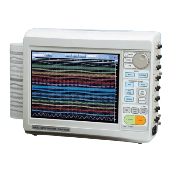
1. RA2300A Overview 1.1. Basic Specifications 1.1.1.Overview and features RA2300A is the product based on the concept of Simple Measurement for Anyone at Anywh ere. New features such as the dynamic waveform view on a large display and the visualized amp setting screen provide simple operation for Pen Recorder users to make quick measur ement In addition, built-in large-capacity HD and memory enable a long continuous recording with multi channels. -
Page 19: Configuration
1. RA2300A Overview 1.2. Configuration 1.2.1. Model The recorder comprises the main recorder unit, amp units, optional units, and standard accessories. Product name Model Remark Command displays can be chosen to be English or Omniace III RA2300A Japanese when placing an order. 1.2.2. -
Page 20: Other Accessories And Consumables
1. RA2300A Overview 1.2.4. Other Accessories and Consumables (1) Accessories for event unit (AP11-105) Name Type No. Remark 0311-5007 2 cables per unit Logic IC cable IC clip cable 0311-5008 4 cables per bag, 2 bags per unit Alligator clip cable 0311-5009 4 cables per bag, 2 bags per unit (2)... -
Page 21: Name And Function Of Each Block
2. Name and Function of Each Block... -
Page 22: Overview Of Blocks
2. Name and Function of Each Block 2.1. Overview of Blocks The RA2300A consists of the following blocks. Display block Operation panel For details 2-3 page For details 2-4 page Front view Printer block Amp block For details 2-6 page Left side Right side Grip... -
Page 23: Display Block
2. Name and Function of Each Block 2.2.Display Block The RA2300A has TFT color LCD with touch panel. This LCD displays screen for setup and user can make settings by touching the setting items that is displayed on the LCD. Turn on the recorder that has the factory default settings. -
Page 24: Operation Panel
2. Name and Function of Each Block 2.3. Operation Panel This section explains button functions on the operation panel block. Buttons related to the job dial Waveform monitoring selection buttons Buttons related to signal recording (11) (10) (12) Buttons related to recording and printing (13) (14) (15) - Page 25 2. Name and Function of Each Block Replay: Replay of recorded data The replay monitor screen, which has gray background, offers replay and observation of the data stored in memory, internal HDD, and external media. Replay format can be selected from among waveform, value, and X-Y.
-
Page 26: Right-Side Block
2. Name and Function of Each Block 2.4. Right-side Block Up to eight optional amps can be installed in this block. (This is an example that installs eight 2CH High-Speed DC Amp Units) Faceplate Power voltage input range and power dissipation is indicated. Power switch This switch turns on or off this recorder. -
Page 27: Upper Surface Block
2. Name and Function of Each Block 2.5. Upper Surface Block Grip Use this grip when carrying. Reserved This slot is a blank slot. RS-232C RS-232C unit (RA23-142, optional) is inserted in this portion. Connection to external machines such as the host computer is made. EVENT Event unit (RA23-145, optional) is inserted in this portion. -
Page 29: Pre-Measurement Procedures
3. Pre-measurement Procedures... -
Page 30: Before Switching On The Power
3. Pre-measurement Procedures 3.1. Before Switching on the Power The preparations for using this recorder and the cautions are explained below. 3.1.1. Usage Environment CAUTION Cautions regarding the installation site. ・Use this recorder on a flat surface. ・Use this recorder in a place that meets the requirements of Installation Category II (CAT II) of the Safety Standards for Electrical Measurement Instrument, JIS-C-1010-1(IEC61010-1). -
Page 31: Ac Power Cable
3. Pre-measurement Procedures This recorder mu t be grounded before power is applied. CAUTION This grounding protection is for the safety of this recorder, as well as for that of the user and peripheral equipment. ・If AC power cable that comes with this recorder is connected to a 3-pin power outlet equipped with a protective conductor pin, the recorder is automatically grounded. -
Page 32: Paper Loading
3. Pre-measurement Procedures 3.2. Paper Loading Load either a paper roll or z-fold paper into this recorder. 3.2.1. Paper Roll Attach the paper holders to the paper roll. Attach a paper holder to both ends of the paper roll. If loading a partially used roll, trim the edges for ease of loading, as shown in the figure below. -
Page 33: Loading Z-Fold Paper
3. Pre-measurement Procedures Pull out the paper Insert the paper in the opening under the platen roller (block roller) of the recording section and pull it out about 10 cm.. (1) Insert the paper under the platen roller Recording chart paper (2) Pull the paper out about 10 cm Platen roller Close the cover... - Page 34 3. Pre-measurement Procedures The procedures for loading the z-fold paper are explained as follows. Place the recorder on top of the paper case Set the paper case on a flat surface with its opening on the left. Then place this recorder on top of the case, aligning the rubber legs with the metal fittings of the case.
- Page 35 3. Pre-measurement Procedures Open the recording section cover by raising the lever After opening the cover, pull out the paper from the case through the opening under the cover. Recording paper cover Pull out the paper through the opening under the cover Thread the paper through the z-fold paper adapter Thread the paper pulled out from under the cover through the z-fold paper adapter as shown below.
- Page 36 3. Pre-measurement Procedures (11) Close the cover After pulling out the paper, making sure it is straight, close firmly pressing with both hands on the both sides of the cover Pull the paper wound on the paper adaptor out the cover as shown route. Place the cover of the box containing the paper in front of the recording section cover to TIPS...
-
Page 37: Insert The Amp Unit
3. Pre-measurement Procedures 3.3. Insert the Amp Unit CAUTION Caution in handling When replacing an amp unit, disconnect the power cable and the signal input cable from the recorder after turning off the power. Replacement of the unit while the power switch is on causes a damage of the unit and the recorder. -
Page 38: Turning On The Power
3. Pre-measurement Procedures 3.4. Turning on the Power When all the preparations are complete, turn on the recorder. <Points to be checked before applying power> Has this recorder been set on a safe place? ● Has this recorder been set under a proper environment? ●... - Page 39 3. Pre-measurement Procedures After power application After applying power, check the following. Confirm that the image is properly displayed on the screen The [Input Monitor] screen will be displayed immediately after power application. Confirm that the paper is fed correctly This can be confirmed by pressing the [Feed] key on the operation panel.
-
Page 41: Operation Flow
4. Operation Flow Flow of Measurement, Basic Settings and Operations... - Page 42 4. Operation Flow (Flow of Measurement, Basic Settings and Operations) 4.1. Operation Flow This recorder records, stores, and replays input signals, following the procedures described below. Before power application Confirm that this recorder has been set in a safe place, and that all the accessories are properly attached.
-
Page 43: Making Basic Settings
4. Operation Flow (Flow of Measurement, Basic Settings and Operations) 4.2. Making Basic Settings This section explains various setting items and icons on the screen. As the display is of a touch panel, settings can be made by directly touching the keys on the display screen. Operation panel Display 4.2.1. -
Page 44: Explanation Of Setting Keys
4. Operation Flow (Flow of Measurement, Basic Settings and Operations) Control block This block is always displayed on the top of the screen and is used for setting function and switching the screen. The contents of the control block change in accordance with a measurement mode and a setting item being selected. - Page 45 4. Operation Flow (Flow of Measurement, Basic Settings and Operations) ● Check boxes When a check box is pressed, a check will alternatively appear and disappear. Several selections are available. ● Radio button When a radio button is pressed, a check will alternatively appear and disappear. Select only one among two or more items.
-
Page 46: Explanation Of Standard Setting Windows
4. Operation Flow (Flow of Measurement, Basic Settings and Operations) 4.2.3. Explanation of standard setting windows This recorder uses common setting windows to set values that are commonly used. ● Numeral input window Use this window to enter numerical values. Current setting Current input value Allowable setting range... - Page 47 4. Operation Flow (Flow of Measurement, Basic Settings and Operations) 3: Input operation section This section operates input character strings from various keys. [Delete line] Erases only the line indicated by the cursor Capital letters and symbols can be input by pressing the [SHIFT] key When the key is pressed, images displayed on the keyboard are changed after the key is highlighted, thereby capital letters and symbols can be input.
-
Page 49: Input Signal Monitor
5. Input Signal Monitor Observing Input Signals... - Page 50 5. Input Signal Monitor (Observing Input Signals) 5.1. Observing Input Signals To observe the signals that are input, use the Input Signal screen. This screen displays the signals that are input in real time. The waveforms can be frozen as necessary. The signals can be seen in Amp, Recording Condition, and Trigger screens, too.
-
Page 51: Displaying Input Waveform Monitor
5. Input Signal Monitor (Observing Input Signals) 5.2. Displaying Input Waveform Monitor The screen below is a screen appears when the Input Signal button is pressed in the Memory Recorder Mode. (8) TOP bar (7) REC icon (6)Value indication (5) Signal name (4) Amplitude scale (1) Waveform display block (3) Position marker... - Page 52 5. Input Signal Monitor (Observing Input Signals) REC icon Status of printing and recording is shown. The contents differ depending on the measurement mode. For more information, see descriptions of measurement modes in Chapters 8 to 12. TOP bar (10) Temporary stop (14) Timer indication (9) Trigger sync (15) Time...
- Page 53 5. Input Signal Monitor (Observing Input Signals) (13) Digital indication Input signal values are indicated in the form of digital value. Pressing this button switches between No and Digital Value. (14) Timer indication f the timer printing is set, the recording time for the next session. If it is not set, nothing is indicated. 16 System Settings (15) Time This portion indicates the current time.
-
Page 55: Auto Setup
6. Auto Setup Automatically Setting Recording Conditions... -
Page 56: Function Overview
6. Auto Setup (Automatically Setting Recording Conditions) 6.1. Function Overview The auto setup function automatically sets recording conditions by referencing the signals currently input. The following parameters are automatically set. ● Auto range (for analog amps only) ● Auto sample To execute this function, press the Auto button. -
Page 57: Auto Sampling
6. Auto Setup (Automatically Setting Recording Conditions) 6.3. Auto Sampling The auto sampling function sets the monitor displaying speed, chart paper feed speed, memory sampling rate, and file recording rate based on the signals currently input. 6.3.1. Target Setup Conditions The relation between settable conditions and mode are as follows. -
Page 59: Amp Units
7. Amp Units... -
Page 60: Settings For Input Units
7. Amp Units 7.1. Settings for Input Units This section covers how to make settings on the Amp Basics and Amp Details screens. For detailed settings for amps, see Instruction Manual Amplifier Units for RA2000A/DL2800A/DF1000A . To set range and waveform printing for input unit, the Amp screen is used. The following screen appears after pressing the Amp button. -
Page 61: Amp Details Screen
7. Amp Units 7.1.2. Amp Details Screen The Amp Details screen appears when the Channel button is pressed on the Amp Basic screen. Detailed channel settings can be made. The following screen is a screen for 2CH High-Resolution DC Amp (AP11-101). (1)Channel (2) Extra Event (3) Batch... -
Page 63: Pen Recorder
8. Pen Recorder Recording Low-speed Signal for Long Time... -
Page 64: Overview Of Pen Recorder Mode
8. Pen Recorder (Recording Low-speed Signal for Long Time) 8.1 Overview of Pen Recorder Mode The Pen Recorder mode offers a pen recorder function, which is dedicated to waveform printing. Chart feed speed and amp settings are made on a screen, which are exactly equivalent to the operability of a pen recorder. -
Page 65: Screen Operation
8. Pen Recorder (Recording Low-speed Signal for Long Time) 8.1. Screen Operation Open the following screen by pressing one button among Input Signal, Amp, Recording Condition, and Trigger buttons in the Pen Recorder mode. (4) Annotation printing (3) Chart feed speed (1) Waveform display block (2) Amp setup block Waveform display block... -
Page 66: Printing Operation
8. Pen Recorder (Recording Low-speed Signal for Long Time) 8.2. Printing Operation Pressing the Start button on the Operation Panel starts printing. Pressing the Stop button stops printing. Sample printing (1) Waveform printing (3) Mark printing (2)System annotation (above) (5)Scale (4) Signal name AAAA... -
Page 67: Stop Due To Error
8. Pen Recorder (Recording Low-speed Signal for Long Time) Marking Marking is printed by pressing the Marking button on the Operation Panel during recording.. Marking time is also printed after ↓M. Example: ↓M17:06:20 2004/11/29 Signal name Character strings set by user by channel are printed. The position of printing is near the zero level of each signal. -
Page 69: Memory Recorder
9. Memory Recorder Recording High-speed Signals... -
Page 70: Overview Of Memory Recorder Mode
9. Memory Recorder (Recording High-speed Signals) 9.1. Overview of Memory Recorder Mode The Memory Recorder mode is useful for recording high-speed signals since the this mode features a highest sampling rate of 1 s. Data recording of a certain period of time before trigger is available. Automatic printing of data on chart recording paper (Auto Copy) or file saving (Backup Filing) is also available. -
Page 71: Recording Condition Setup
9. Memory Recorder (Recording High-speed Signals) 9.2. Recording Condition Setup Open the following screen by pressing the Recording Condition button on the Operation Panel to set the recording conditions for Memory Recorder. The recording condition setup should be made while the recorder stops its operation. -
Page 72: Memory Recording Condition Setup Block
9. Memory Recorder (Recording High-speed Signals) 9.2.2. Memory Recording Condition Setup Block (1) Sampling rate (2) Memory Block Size (3) Memory Block & Status Indication (4) Sample recording image (5) Pre-trigger (6) Memory Recording Operation (7) Auto data output (8) Output range (9) File output path Sampling rate Sampling rate for memory recording is set. - Page 73 9. Memory Recorder (Recording High-speed Signals) Recording sample Trigger position for entire recording and sample for output range is displayed. Recording time: Pre-trigger and post-trigger and total recording time is displayed. Pre-trigger Recording size before trigger can be set in percentage. Changing this setting renews the sample recording image, which enables a user to confirm recording time allocation.
- Page 74 9. Memory Recorder (Recording High-speed Signals) File output path The file save target path can be specified. Pressing the button opens the following dialog box. File save path a) b) c) d) a) Save target path Save target path is specified. As well as internal HDD, USB storage drive can be specified. b)...
-
Page 75: Recording Operation
9. Memory Recorder (Recording High-speed Signals) 9.3. Recording Operation Pressing the Start button on the Operation Panel starts the Memory Recording. After the recording start, the recorder is in the wait status for trigger detection. Pressing the Stop button stops the operation forcibly. -
Page 77: Hd Recorder
10. HD Recorder Recording Data in Internal... -
Page 78: Overview Of Hd Recorder Mode
10. HD Recorder (Recording data in the internal HDD) 10.1. Overview of HD Recorder Mode The HD Recorder mode can record data in the internal hard disk, which is suitable for a long-time measurement. In addition, waveform chart paper printing can be made with the HD recording at the same time. -
Page 79: Recording Condition Setup
10. HD Recorder (Recording data in the internal HDD) 10.2. Recording Condition Setup Open the following screen by pressing the Recording Condition button on the Operation Panel to set the recording conditions for HD Recorder. The recording condition setup should be made while the recorder stops its operation. -
Page 80: Hd Recording Setup Block
10. HD Recorder (Recording data in the internal HDD) 10.2.2. HD Recording Setup Block (1) File save path (2) Recording rate (4) Recording length (3) Free space in internal HDD (5) Recording start (7) Data format (6) Filing format (8) Waveform chart printing (1) File save path Save target path for HD recording is indicated. -
Page 81: Recording Operation
10. HD Recorder (Recording data in the internal HDD) (4) Recording length The length of recording in HD is indicated in data count and re cording time. Setup can be made in the setup dialog box that i s displayed when the button is pressed. D... - Page 82 10. HD Recorder (Recording data in the internal HDD) (7) Data format Setup item Description Peak One data consist of two values: maximum and minimum values. Regardless of recording speed, peak data is stored with the highest A/D conversion speed of amp. It is possible to observe waveform having high-frequency element for long period of time.
-
Page 83: Start Of Measurement
10. HD Recorder (Recording data in the internal HDD) 10.3. Recording Operation Pressing the Start button on the operation panel starts HD recording. While recording is made, pressing the Stop button forcibly stops the recording. 10.3.1. Start of Measurement Pressing the Start button on the operation panel starts HD recording. If the setup in which the start of recording is initiated with a trigger signal, the start of recording is made with a trigger detection. -
Page 84: Hd Recording Specifications
10. HD Recorder (Recording data in the internal HDD) 10.4. HD Recording Specifications 10.4.1. Recording File Size Calculation This section covers how to calculate file capacity in HD recording. The file size can be calc ulated using the following parameters. Parameter Remark Recording length... -
Page 85: Multi Recorder
11. Multi Recorder Separately Executing Waveform Printing, Memory Recording and HD Recording... -
Page 86: Overview Of Multi Recorder Mode
11. Multi Recorder - Separately Executing Waveform Printing, Memory Recording and HD Recording 11.1.Overview of Multi Recorder Mode Multi Recorder enables operations of Memory Recorder, HD Recorder, and waveform printing at the same time. This Recorder is suitable to the measurement such that data before or after the trigger is precisely recorded while long-time recording is made. -
Page 87: Recording Condition Setup
11. Multi Recorder - Separately Executing Waveform Printing, Memory Recording and HD Recording 11.2. Recording Condition Setup Open the following screen by pressing the Recording Condition button on the Operation Panel to set the recording conditions for HD Recorder. The recording condition setup should be made while the recorder stops its operation. -
Page 88: Multi Recorder - Setup For Recording Condition
11. Multi Recorder - Separately Executing Waveform Printing, Memory Recording and HD Recording Multi Recorder - Setup for Recording Condition 11.2.2. ① File output path Memory Block ②Memory recording setup block The setup steps are the same as in 9. Memory Recorder. Pretrigger Logging Mode Filing recording... - Page 89 11. Multi Recorder - Separately Executing Waveform Printing, Memory Recording and HD Recording ① File output path The path for file save can be specified. Pressing the key opens the following dialog box. a) Path for file save Specify the path for file save. You can choose a USB storage drive other than internal HDD. b)...
-
Page 90: Recording Operation
11. Multi Recorder - Separately Executing Waveform Printing, Memory Recording and HD Recording The fastest chart feed speed is 100 mm/s. If the value equivalent to recording speed NOTE exceeds this value, printing with fastest speed will be made. Chart feed speed setup c)... -
Page 91: X-Y Recorder
12. X-Y Recorder... -
Page 92: Overview Of X-Y Recorder Mode
12. X-Y Recorder 12.1. Overview of X-Y Recorder Mode The X-Y Recorder mode is a mode that is specialized to real-time X-Y printing, which outputs X-Y waveforms on chart paper. Data sample speed and amp settings are available on a screen. To set the recorder to the X-Y recorder mode, use the Measurement Mode tab on the System screen. -
Page 93: Screen Operation
12. X-Y Recorder 12.2. Screen Operation Press any button among Input Signal, Amp, Recording Condition, and Trigger buttons. The following screen appears. (5) Print Icon (7) X-Y Recorder control block (6) File Icon (8) X-Y axis settings (4) Amp settings (3) Y axis scale (2) X axis scale (1) X-Y monitor... - Page 94 12. X-Y Recorder (5) Print Icon Pressing this icon executes the printout for the X-Y monitor currently displayed. The following table illustrates the X-Y printing status during X-Y recording. Normal To execute Error (6) File Icon Pressing this icon button sets file recording to ON or OFF. Setting to ON saves data of X-Y recording in internal HDD file.
- Page 95 12. X-Y Recorder (8) XY-axis setting a) Channel setting (X axis) a) Channel settings (Y axis) b) Pen-up and down (Y axis 1) a) Channel setting (Y axis 2) b) Pen-up and down (Y axis 2) a) Channel settings (Y axis 3) b) Pen-up and down (Y axis 3) a) Channel settings One channel for X axis and three channels for Y axes can be made.
-
Page 96: Printing Operation
12. X-Y Recorder 12.3. Printing Operation Pressing the Start button on the operation panel clears X-Y data display from the X-Y monitor and, shortly after that, re-displays the X-Y data display again. Pressing the Stop button stops the X-Y monitor and prints the X-Y waveforms on chart paper. If the file saving is set to be valid during this period, recording data can be saved in a file. -
Page 97: Trigger Settings
13. Trigger Settings Capturing Target Data to be Recorded... -
Page 98: Trigger Mode Description
13. Trigger Settings (Capturing Target Data to be Recorded) 13.1. Trigger Mode Description This recorder provides with four trigger modes: OR, AND, WINDOW, and OFF. Other than these modes, there are manual trigger and external triggers, which are valid regardless of the input signal. 13.1.1. -
Page 99: Trigger Mode - Operation At Window
13. Trigger Settings (Capturing Target Data to be Recorded) 13.1.3. Trigger Mode – Operation at WINDOW When the signal level enters into the pre-set range of the trigger source channel (i.e. IN) or goes out of the range of the trigger source channel (i.e. OUT), a trigger is generated. The trigger setup can be made for all analog channels. -
Page 100: Manual Trigger/External Trigger
13. Trigger Settings (Capturing Target Data to be Recorded) 13.2. Manual Trigger/External Trigger Regardless of trigger modes, trigger is activated manually or externally, thereby initiating the recording. 13.2.1. Manual Trigger Pressing the Manual/Marking button on the operation panel generates a trigger irrespective of other trigger settings. -
Page 101: External Trigger Input/Output Circuit
13. Trigger Settings (Capturing Target Data to be Recorded) 13.2.4. External Trigger Input/Output Circuit External trigger input circuit ● Input signal: 0 to 5-V voltage signal (falling edge) +3.3V +3.3V 10kΩ TRIGGER 100Ω トレラント 機能付 低電圧 ロジック External trigger output circuit ●... -
Page 102: Method Of Trigger Settings
13. Trigger Settings (Capturing Target Data to be Recorded) 13.3. Method of Trigger Settings Trigger is a timing signal to start recording. The RA2300A has a variety of trigger function, thus enabling efficient data recording and printing. Pressing the Trigger button on the Operation Panel, opens the Trigger Settings screen. -
Page 103: Settings By Trigger Mode
13. Trigger Settings (Capturing Target Data to be Recorded) 13.4. Settings by Trigger Mode 13.4.1. Trigger Mode OR Trigger is generated upon the satisfaction of either of the trigger conditions set as the trigger source. The OR setting for all channels are available. Setting the trigger mode to OR. -
Page 104: Trigger Mode Window
13. Trigger Settings (Capturing Target Data to be Recorded) 13.4.3. Trigger Mode WINDOW When the signal level enters into the pre-set range of the trigger source channel (i.e. IN) or goes out of the range of the trigger source channel (i.e. OUT), a trigger is generated. The trigger setup can be made for all analog channels. -
Page 105: Trigger Mode Off
13. Trigger Settings (Capturing Target Data to be Recorded) 13.4.4. Trigger Mode OFF Trigger caused by a signal input into amp is not made. Only the manual and external triggers are effective. Setting the trigger mode to OFF When printing is made, only the trigger made after the startup is effective. If the trigger NOTE condition is satisfied before the start of recording, the status enters into the wait for next trigger condition. -
Page 106: Trigger Settings For Event Amp
13. Trigger Settings (Capturing Target Data to be Recorded) 13.6. Trigger Settings for Event Amp Trigger settings for event amp differs from those of other amps. The settings are made in the following screen. Trigger settings are made when the check box is ticked. -
Page 107: Trigger Settings For Event Unit
13. Trigger Settings (Capturing Target Data to be Recorded) 13.7. Trigger Settings for Event unit Trigger settings for event Unit (Optional RA23-145) and event Box (Optional RA23-146) differs from those of other amps. The settings are made in the following screen. AND: When all trigger conditions that have been set are satisfied, a trigger is activated. -
Page 109: Replay Display
14. Replay Display Displaying Recording Data... -
Page 110: Overview Of Replay Monitor
14. Replay Display (Displaying Recording Data) 14.1. Overview of Replay Monitor The Replay screen is used to display the data recorded in memory or file. Waveform display for recorded data is available after the data is selected in the list. (10) (11) (12) -
Page 111: Replay Data Selection
14. Replay Display (Displaying Recording Data) 14.2. Replay Data Selection To select the screen to be displayed on the Replay monitor, open the following screen by pressing the Data Selection button. (1) Reference path (2) Data list (3) Data selection (4) Recording info Reference path This indicates data reference target path. -
Page 112: Waveform Display Region
14. Replay Display (Displaying Recording Data) 14.3. Waveform Display Region The thumbnail that indicates waveform display region is displayed on the Replay Monitor screen and the Y-T waveform. (1) Waveform display region (3) Thumbnail (2) Cursor position (4) Auto scroll (4) Auto scroll Waveform Display Region This is the time axis domain currently being displayed. -
Page 113: Digital Indication
14. Replay Display (Displaying Recording Data) 14.4. Digital Indication Indications for digital values and cursor position information for measurement values can be made. 14.4.1. Digital Indication Measurement values are indicated in digital values. Time-axis position to be displayed changes depending on the LED status. X1 LED On ●... -
Page 114: Signal Settings
14. Replay Display (Displaying Recording Data) 14.5. Signal Settings It is possible to confirm the recording conditions for channel of the signal that are recorded as data and change the setup for waveform display. Press the Signal Setting button on the upper part of the Replay screen. -
Page 115: Jump
14. Replay Display (Displaying Recording Data) 14.6. Jump Jump of Y-T waveform display position can be made after the time axis position is specified. Pressing the Jump button on the upper part of the Replay screen displays the following screen. 14.6.1Basic Jump 14.6.2Time Jump 14.6.1. -
Page 116: Maximum/Minimum Search & Jump
14. Replay Display (Displaying Recording Data) 14.6.4. Maximum/Minimum Search & Jump Searching for maximum and minimum values for all analog channels is available. Jump to the searched position is possible after listing the result. Operation steps for the maximum and minimum values search are as follows. Use the Max and Min tab on the jump screen. -
Page 117: Event Jump
14. Replay Display (Displaying Recording Data) 14.6.5. Event Jump Marking information that is recorded in the recorded data is searched and jump is made. The Event tab on the Jump screen is displayed. Marking jump is executed when a search direction button is pressed. -
Page 118: Output Setup
14. Replay Display (Displaying Recording Data) 14.8. Output Setup Displayed data can be printed out or exported into a file. To execute data output, press the Output Setup button on the upper part of the Replay screen. Then the following screen opens. 14.8.1. -
Page 119: Specifying Number Of Skip In Csv
14. Replay Display (Displaying Recording Data) 14.8.4. Specifying Number of Skip in CSV Use the (4) button to specify the number of skip in CSV save. Data will be rough if skipping is specified but it is possible to make file size small. TIPS 14.8.5. -
Page 120: X-Y Waveform Display
14. Replay Display (Displaying Recording Data) 14.9. X-Y Waveform Display To display replay data in the X-Y graph, press the X-Y icon on the top of the screen. If the recorded data is the Sample format, X-Y display is made; if the data is the Peak format, X-Y display is not made. Data selection This portion displays the data file name whose data is being displayed. -
Page 121: Display And Printing
15. Display and Printing Settings for Monitor Display and Printing... -
Page 122: Settings For Display And Printing
15. Display and Printing (Settings for Monitor Display and Printing) 15.1. Settings for Display and Printing Display and Printing is used to set X-Y display of waveforms or printing format for waveform. Pressing the Display and Printing button on the Operation Panel opens the screen for settings. (10) (11) 15.1.1. -
Page 123: Cursor Value Indication
15. Display and Printing (Settings for Monitor Display and Printing) 15.1.5. Cursor Value Indication To display the cursor position information on the replay monitor, tick the check box of (7) on the Display and Printing screen. 15.1.6. Waveform Segmentation It is possible to set the number of waveform segmentation with the (8) button on the Display and Printing screen. -
Page 125: System Setup
16. System Setup Other Functions... -
Page 126: System Setup List
16. System Setup (Other Functions) 16.1.System Setup List 16.1. System Setup List ......................16-2 16.2. Commonly Used System Screen ................. 16-3 16.2.1. Termination..........................16-3 16.2.2. USB Drive Disconnection ....................... 16-3 16.3. Measurement Mode ....................... 16-4 16.3.1. Screen Display upon Startup ....................16-4 16.3.2. -
Page 127: Commonly Used System Screen
16. System Setup (Other Functions) 16.2.Commonly Used System Screen Termination and USB Storage Disconnection, which are frequently used in the System screen, are placed on the front. 16.2.2USB Drive Disconnection 16.2.1Termination 16.2.1. Termination This button initiates the termination processing of the recorder. After message of “You can shut off the power”... -
Page 128: Measurement Mode
16. System Setup (Other Functions) 16.3. Measurement Mode In the Measurement Mode screen of the System screen, measurement mode settings for this recorder as well as saving, readout, and initialization of all setup information can be made. Pressing the System button and the Measurement Mode tab on the operation panel displays the following screen. -
Page 129: Setup Value Save
16. System Setup (Other Functions) 16.3.3. Setup Value Save The settings of this recorder can be saved in or read from the internal memory. Comments can be entered, which makes it useful to recognize file. Additionally, setup can be indicated as a list. Setup value save and readout (My Setup) Comment Time... -
Page 130: File Operations
16. System Setup (Other Functions) 16.4. File Operations File operations are made for the drives through the File Operation tab on the System screen. Press the System button on the operation panel and the File Operation tab to show the following screen. Current Folder Browse File Name... -
Page 131: Copy
16. System Setup (Other Functions) 16.4.1. Formatting Formatting of the current referenced drive can be made. Pressing the Format button in the File Operation tab in System displays the following screen. Date in the drive is deleted when formatting is made. It is recommended to back up the NOTE important data in other media. - Page 132 16. System Setup (Other Functions) 16.4.5. Memory Save The block data stored in memory can be saved. The following screen appears by pressing the Memory Save button after moving to the folder where data will be saved in the File Operation tab in the System screen.
- Page 133 16. System Setup (Other Functions) 16.4.6. Environment Save Setup information can be saved in a file. It is useful to save the setup information in external media or read out it from another RA2300A recorder. The following screen appears by pressing the Environment Save button after moving to the folder where saving is made using the File Operation tab in the System screen.
-
Page 134: Recording Settings
16. System Setup (Other Functions) 16.5. Recording Settings Press the System button, and then press the Recording Settings tab. The following screen appears. 16.5.1Recording Channels 16.5.2Data No. Setting 16.5.3Print Settings 16.5.4Recording Speed Table 16.5.5Time-axis Representation 16.5.6Timer Recording Settings 16.5.7External Sync Rate Setting 16.5.1. -
Page 135: Data No. Setting
16. System Setup (Other Functions) 16.5.2. Data No. Setting The number that is assigned to the measurement data can be changed. In the System screen use the Recording Settings screen. Pressing Data No. displays numeric pad, enabling value data entry. The data number increments automatically after recording. -
Page 136: Recording Speed Table
16. System Setup (Other Functions) 16.5.4. Recording Speed Table User can sets the speed for waveform chart printing, memory recording, and HD recording. Press the System screen, and then press the Recording Settings screen. Pressing Recording Table button displays the following screen. 16.5.5. -
Page 137: External Sync Rate Setting
16. System Setup (Other Functions) Specify the start interval of time (1 H) Specify the operation time. (20min) The actual recording operation time may be shortened depending on the recording length settings. When the timer function is set, a symbol of clock is displayed upper part of the TIPS screen. -
Page 138: Communication Settings
16. System Setup (Other Functions) 16.6. Communication Settings Press the Communication Settings tab on the System button on the Operation Panel. The following screen appears. (1) UPS Connection (2) Communication Function RS-232C Settings (4) LAN Settings To use the USP or RS-232C function, RS-232C Unit (RA23-142, optional) is necessary. NOTE UPS Connection Connection to uninterruptible power supply (UPS) can be made by ticking the check box. - Page 139 16. System Setup (Other Functions) RS-232C Settings RS-232C communication protocol can be set. Pressing this button displays the screen below. Set the RS-232C conditions in this screen. Line speed Data bits Stop bits Parity EVEN Flow control Delimiter Time-out Cancel LAN Settings Communication protocol setup for the LAN connection is made.
-
Page 140: Auxiliary Settings
16. System Setup (Other Functions) 16.7. Auxiliary Settings Press the System button on the Operation Panel, and then press the Auxiliary Settings tab. The following screen appears. 16.7.1Buzzer/Clicking Sound 16.7.2Auto Display Light-off 16.7.3Screen Copy Output Destination 16.7.4Key lock Password Settings 16.7.5Feed Length Setting 16.7.1. -
Page 141: Key Lock Password Settings
16. System Setup (Other Functions) 16.7.4. Key lock Password Settings Pressing button (4) on the Auxiliary Settings screen displays character entry screen and enables registration of key lock password. The key lock password is used to resume from the key lock condition. -
Page 142: Maintenance
16. System Setup (Other Functions) 16.8. Maintenance Press the System button on the Operation Panel and Maintenance. The following screen appears. 16.8.1Version Indication 16.8.2Test Print 16.8.3Data Printing 16.8.4Time Calibration 16.8.1. Version Indication Product serial number and program version are indicated. Press the Version Indication button on the Maintenance screen in System. -
Page 143: Test Print
16. System Setup (Other Functions) 16.8.2. Test Print Test printing is made in order to check the printer printing quality. Pressing the Test Print button on the Maintenance screen in System opens the confirmation screen. Pressing “Execute” button starts the test print. -
Page 145: How To Use Optional Units
17. How to Use Optional Units... -
Page 146: Connecting Optional Units
17. How to Use Optional Units 17.1.Connecting optional units Please insert blank panel into empty slots when optional units are not connected in WARNING order to avoid electrical shock and to prevent damages to the recorder unit caused by irruptions of extraneous substances Please turn the power off and unplug power strip from the recorder unit before CAUTION connecting or disconnecting optional units. -
Page 147: Remote Unit (Ra23-144)
17. How to Use Optional Units 17.2. Remote Unit (RA23-144) 17.2.1. Overview Start/Stop of recording/printing, chart feed, marking, input/output for synchronized operations can be controlled by electric signals. Also, waveform printing synchronized to an external pulse signal (chart feed) and memory acquisition are possible. Other features include prevention of data file destructions by electric power failure and output of recorder unit error, etc. -
Page 148: To Synchronize To External Pulse And Perform Waveform Chart Printing And Printing
17. How to Use Optional Units 17.2.3. To Synchronize to External Pulse and Perform Waveform Chart Printing and Printing Waveform recording, input monitor, filing acquisitions can be synchronized to external pulse. Instructions on how to connect remote terminals and how to set up the recorder unit are explained in the below. -
Page 149: Compatibilities With Conventional Products (Waveform Chart Printing)
17. How to Use Optional Units 17.2.4. Compatibilities with Conventional Products (Waveform Chart Printing) This product is compatible with the conventional products, so it is possible to set up external pulse control. Setup is done by changing external synchronization ratios from acquisition set up tab in System Screen. -
Page 150: Start/Stop Recording (Start/Stop Button)
17. How to Use Optional Units 17.2.6. Start/Stop recording (Start/Stop button) It functions the same way as pressing the Start button on the panel and it starts acquisition. The A3 pin (REC IN) of remote terminal is controlled externally. For the common, use the A4 pin. REC IN Signal ↑... -
Page 151: Parallel Operation
17. How to Use Optional Units 17.2.11. Parallel Operation This product can perform recording, chart feed, marking functions simultaneously by connecting remote terminals in parallel with multiple recorder units. Instructions below show how to connect (1) as a master recorder unit. Name Pin No. -
Page 152: Event Unit (Ra23-145)
17. How to Use Optional Units 17.3.Event Unit (RA23-145) 17.3.1.Overview Event unit performs level judgment (H Level, L Level judgment) of power voltage. It is possible to manage up to 16 inputs. 17.3.2. Connector/Pin Location Connector Type : 8850-034-170-LD Attached cables Name of Signal Color of Color of... -
Page 153: Connector/Pin Location
17. How to Use Optional Units 17.4.Event Box (RA23-146) 17.4.1.Overview and features This event box is the unit for check of both voltage input level (H level and L level) and contact input level (H: Short and L: Open). The event box (RA23-146) comprises following elements: 1) Event box I/F (RA23-327) 2) Event box (RA23-328) 3) Cable (0311-5257) -
Page 154: Rs-232C Unit (Ra23-142)
17. How to Use Optional Units 17.5. RS-232C Unit (RA23-142) 17.5.1.Names of each parts and their functions Function Connect to host computer and control Omni ace by command. Specification JIS X5101 (former C6361)compliant Data Format Bit Serial Transfer speed 38400, 19200, 9600, 4800, and 2400[bps] Transfer format asynchronous communication, total square transmission method... -
Page 155: Ac Bridge Excitation Unit (Ra23-143)
17. How to Use Optional Units 17.6. AC Bridge Excitation unit (RA23-143) 17.6.1.Names of each parts and their functions Connector INT:OSC power voltage output EXT:OSC power voltage input Select Switch INT(Internal):Mater (LED ON) (LED ON):Slave(LED OFF) Function Bridge excitation when 2CH AC Strain Amp Unit (AP11-104) is in use. Bridge excitation 2 Vrms, sin wave 5kHz Possible to synchronize with other RA2300A with internal AC Bridge Excitation... -
Page 157: Maintenance And Cleaning
18. Maintenance and Cleaning... -
Page 158: Handling And Storing Recording Paper And Data
18. Maintenance and Cleaning This is precision equipment, so do not allow anyone other than a qualified WARNING technician from our company to open the main unit case. 18.1.Handling and Storing Recording Paper and Data NOTE Care is required when handling the thermo-sensitive paper used by this instrument. -
Page 159: Cleaning And Preserving The Thermal Head
18. Maintenance and Cleaning 18.4.Cleaning and Preserving the Thermal Head 18.4.1. Cleaning If recording for long periods of time, the heat dissipating part of this instrument's thermal head may become clogged with paper remains, etc. If the head is dirty, the quality of the printing and image reproduction will be reduced, so in this case the head will require cleaning. -
Page 161: Troubleshooting
19. Troubleshooting... -
Page 162: Troubleshooting And Inspection
19. Troubleshooting 19.1.Troubleshooting and Inspection If the recorder does not operate normally or need to be repaired after following the NOTE instructions for abnormal conditions, please contact our sales offices listed at the end of this manual. Problem Possible cause Instruction Refer to Chapter... -
Page 163: Frequently Asked Questions (Q&A)
19. Troubleshooting 19.2.Frequently Asked Questions (Q&A) This section covers frequently asked questions. Question List Q 1: A copy of a screen can be saved into a file? ................. 19-4 Q 2: Please inform details of the folder or directory that automatically generated after acquisition..19-4 Q 3: What is the relation between the available acquisition time and the media (recording medium) space? ............................ - Page 164 19. Troubleshooting Q 1: A copy of a screen can be saved into a file? Answer The copy can be saved in bitmap format. Select the sub setting tab by the System button and specify the folder in Save Screen Copy Destination.
- Page 165 19. Troubleshooting Q 3: What is the relation between the available acquisition time and the media (recording medium) space? Answer The available time depends on Media space, a Data type, and a Channel Number. The available time can be roughly estimated by the following formulas. Sample time: Acquisition length = (media space –...
- Page 166 19. Troubleshooting Q 7: After changing the speed of recording paper feeding or acquisition, the view of an input monitor is also changed. Answer A memory external synchronization is recorded by gating 1μs internal clock with an external clock. A recording operation is available up to about 1μs but the 1μs maximum delay from an external clock develops.
- Page 167 19. Troubleshooting Q 14: What is the “peak” format? Answer One-point data is composed of both maximum and minimum values. Maximum and minimum points are detected at the maximum rate of amp. This controls the number of data and allows completely catching changes in a signal. The following data is peak format.
-
Page 169: Specifications
20. Specifications... -
Page 170: Configuration
20. Specifications 20.1.Configuration 20.1.1. Model This product is configured with the recorder unit, optional units, and a set of standard accessories. Description Model Comment OMNIACE III RA2300A If you wish to purchase the English version, specify this when making an order. 20.1.2. -
Page 171: Options And Consumables
20. Specifications 20.1.4. Options and Consumables Options for Event Amp Unit (AP11-105) Description Model Comment Logic IC Code 0311-5007 2 pieces per unit IC Clip Code 0311-5008 4 pieces per a bag, 2 bags per unit Alligator Clip Code 0311-5009 4 pieces per a bag, 2 bags per unit Options for Remote Unit (RA23-144) Description... -
Page 172: Basic Specifications
20. Specifications 20.2.Basic Specifications 20.2.1. Recorder Unit Specifications Input part Slot Number 8 (mixing different amp units are available) Display Equipment 12.1 inches TFT color LCD Display Part Available Display Area 245.88mm x 184.3mm (1024 x 768 dots) Internal Acquisition data capacity: 2MW/Ch memory Internal HDD Drive 40GB (including approx 5GB of system area) -
Page 173: Recording Function
20. Specifications 369.5±2(W)×164.5±2(H)×301±2(D)mm (including rubber legs) Dimension Excluding protrusion (knurl screws in an Amp part and a jog dial) Apperance/ Approx. 7.0kg Main body only (excluding Amps and options) Weight Approx. 7.8kg with options and 4 units of 2CH High -resolution DC amps Weight installed (including RS-232C, AC Bridge Power Supply, and Recording paper. -
Page 174: Trigger Function
20. Specifications 20.2.4. Trigger Function Basic Function Internal Trigger Trigger by input signals from each amp. Trigger Source Manual Trigger Trigger by manual trigger key on the operation panel External Trigger Trigger by trigger inputs Pre-trigger From 0 to 100%, 1% step Trigger Filter From 1 to 65534 samples Trigger... -
Page 175: File Function
20. Specifications 20.2.5. File Function Available Drive Drive Name Drive No. Available Media (Drive) Built-in HDD C fixed 40GB (including approx 5GB of system area) External (USB) C to I USB memory Connecting Drive The USB memory with a security function cannot be used. *Only recommended drives and media are supported. -
Page 176: Monitor Displaying And Setting Function
20. Specifications 20.2.6. Monitor displaying and setting function Use the Operation Panel (including jog dial) and the touch panel to configure various settings Input Setting Screen Use this screen to configure the waveform of input signals and input setting. Digital values and cursor values of an input signal can be displayed. Operation Panel Configuration Input... -
Page 177: Specifications By Each Measurement Mode
20. Specifications 20.3.Specifications by each measurement mode 20.3.1. Memory Recorder mode Use this mode to acquire measuring data of input signals to the main body’s memory This mode is mainly used for measuring high-speed phenomenon based on the trigger After the recording, the data can be displayed on a playback monitor and be copied. -
Page 178: Hd Recorder Mode
20. Specifications 20.3.2. HD Recorder Mode Use this mode to acquire measuring data of input signals directly to a built-in HDD. Acquisition method can be configured sample or peak. Acquisition Push Start key on the operation panel to start. (Staring with built-in timer is Operation also available) Acquisition Drive... -
Page 179: Multi Recorder Mode
20. Specifications 20.3.5. Multi Recorder mode Memory Recording The speed is set with sampling cycle. 1 to 999 s, 1 to 999 ms, and 1 to 100 s. Recording speed 1 to 999 s, 1 to 999 ms, 1 to 100 s can be set for Users 1 and 2. * Recording started by external clock synchronization (External sampling input from remote unit) Memory size... -
Page 180: Acquisition Data Output
20. Specifications 20.4.Acquisition Data Output Record a part of or all recording data. In addition, the data can be saved in a different format. Where to output Output Format Output Method Waveform Narrowing and Extending the time axis of a wave form is Recording available. -
Page 181: Remote Unit (Ra23-144:Optional)
20. Specifications 20.7.Remote Unit (RA23-144:Optional) Electric signals controls start or stop of recording/recording, paper feeding, mark input, and input/output for synchronized operation. In addition, recording waveforms and Function acquiring memory synchronized external pulse signals are available. External input enables preventing the corruption of data files by power failure and the output of a main unit’s errors. -
Page 182: Event Unit(Ra23-145:Optional)
20. Specifications 20.8.Event Unit(RA23-145:Optional) Event Unit is the unit to judge voltage level(H-Level、 L-Level judgement). One unit Function accepts up to 16 inputs. Input Voltage Rangex Dectation Levelx Input Current Specification HIGH Level more than 2.0 V Resistance 1 k ohm 0 to +5V LOW Level less than 0.8V pull-up +5V... - Page 183 20. Specifications 20.9.Event Box (RA23-146: Optional extras)) This event box is the unit for check of both voltage input level (H level and L level) Function and contact input level (H: Short and L: Open). 16.inputs are usable. The event box (RA23-146) comprises following elements: 1) Event box I/F (RA23-327) Constitution 2) Event box (RA23-328)
-
Page 184: Rs-232C Unit (Ra23-142:Optional)
20. Specifications 20.10.RS-232C Unit (RA23-142:Optional) Function Access host computer, control OMNIACE by commands. JIS X5101 (formerly C6361)compliance Data type Bit Serial Transmission 38400, 19200, 9600, 4800, and 2400[bps] Speed Transmission Start-Stop Transmission, Full-duplex transmission Specification Mode Start Bit 1[bit] Data Bit 7,8[bit] Stop Bit 1,2[bit]... -
Page 185: Dimensions Of Ra2300A
20. Specifications 20.13.Dimensions of RA2300A 20.13.1.Dimensions of RA2300A Standard Unit 369.5 14 150.5 } 2 6 { Ì Å è p l W L ø l W [ ³ M4 ~ 5mm 21.50 325.5 } 0.3 22.50 20-17 RA2300A Recorder (7001754-R01) -
Page 186: Option Unit Outline Drawing
20. Specifications 20.13.2. Option Unit Outline Drawing RS-232C Unit Remote Unit 20-18 RA2300A Recorder (7001754-R01) - Page 187 20. Specifications Event Unit AC Bridge Power Supply Unit 20-19 RA2300A Recorder (7001754-R01)
- Page 188 20. Specifications Event Box 20-20 RA2300A Recorder (7001754-R01)
-
Page 189: Cables・Probes・Spare Parts List
・ ・ 21. Cables Probes Spare Parts List... -
Page 190: Cables List
21. Cables・Probes・Spare Parts List 21.1. Cables List Name(model) Form Comment AC Power Code Length 2.5m 100 V (0311-5044) AC Power Code Length 3.5m 200 V (0311-5112) Signal input cable Safety BNC Length 2m (0311-5175) ←→Alligator Clip Black - Signal input cable Safety BNC Length 2m (0311-5177) - Page 191 21. Cables・Probes・Spare Parts List Name (System) Form Comment Logic IC code Round DIN8P Plug Length 1.5m (0311-5007) ←→EI Connector Blown, Black Red, Black Orange, Black Yellow, Black Thin wire color Blown, Black 1ch Red, Black Orange, Black Yellow, Black IC clip code EI Connector Length 15cm Blown...
- Page 192 21. Cables・Probes・Spare Parts List Name(System) Form Comment Event input cable Round DIN8P Length 1.5m (0311-5001) Thin cable color Blown ……1ch ……2ch Orange ……3ch Yellow ……4ch Shield ……GND(0V) White ……+15V Output *When the white+15V output wire is not used, make sure to terminate.
- Page 193 21. Cables・Probes・Spare Parts List Name(System) Form Comment Trigger input cable Length 2m (0311-5084) ←→Alligator Clip Red…+ Black…- Mold Color : Red Output cable BNC←→BNC Length 2m (47226) Remote cable Connector:28 pin Length 1.5m (00311-5251-0000) No cut Event cable Connector:34 pin Length 1.5m (00311-5252-0000) No Cut...
- Page 194 21. Cables・Probes・Spare Parts List 21.2. Probes・Clamp Meter List Name(System) Form Comment Floating voltage probe 4 Input (1539) Alligator Clip ←→Round DIN8P Plug Voltage regulation 1 Input probe (1540: 100/120 VAC) (1543: 220/240 VAC) ・Alligator Clip ←→Round DIN8P Plug ・Banana Plug ←→Pin Chip 21.3.Spare Parts List System...
- Page 195 To Ensure Prolonged Use A&D Company,Limited. Thank you for purchasing an A&D Company,Limited. product. To ensure prolonged use of the product that you have purchased, we offer the following lineup of maintenance services. 1. Warranty Period The warranty period for this product is one year from the date of purchase. In case of a failure, the product will be repaired free of charge (only if the failure is ascribable to the responsibility of A&D).
- Page 196 (1) This manual may not be reproduced to any form in whole or in part. (2) Then contents in this manual may be updated without prior notice. OmniaceⅢ RA2300A MAINFRAME Instruction Manual (7001754-R01) Edition: March 2013 Edition: June 2014 Edition: June 2014 Edition:...