Sign In
Upload
Manuals
Brands
A&D Manuals
Measuring Instruments
Omniace III RA2300A
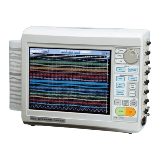
A&D Omniace III RA2300A Manuals
Manuals and User Guides for A&D Omniace III RA2300A. We have
1
A&D Omniace III RA2300A manual available for free PDF download: Instruction Manual
A&D Omniace III RA2300A Instruction Manual (196 pages)
Brand:
A&D
| Category:
Measuring Instruments
| Size: 4.84 MB
Table of Contents
Safety Measures - Warning and Cautions
4
Warranty - General
7
Terms and Symbols in this Manual
8
Liquid Crystal Display
8
Overview of Windows XP Embedded
9
Table of Contents
10
RA2300A Overview
17
Basic Specifications
18
Overview and Features
18
Features
18
Configuration
19
Model
19
Recorder and Amp Unit
19
Standard Accessories (Display in Japanese and 100VAC)
19
Other Accessories and Consumables
20
Other Optional Equipment
20
Name and Function of each Block
21
Overview of Blocks
22
Display Block
23
Operation Panel
24
Right-Side Block
26
Upper Surface Block
27
Pre-Measurement Procedures
29
Before Switching on the Power
30
Usage Environment
30
Before Connecting AC Power Cable
30
AC Power Cable
31
Paper Loading
32
Paper Roll
32
Loading Z-Fold Paper
33
Insert the Amp Unit
37
Turning on the Power
38
Operation Flow
41
Making Basic Settings
43
Explanation of Basic Screen Settings
43
Explanation of Setting Keys
44
Explanation of Standard Setting Windows
46
Input Signal Monitor
49
Observing Input Signals
49
Displaying Input Waveform Monitor
51
Auto Setup
55
Function Overview
56
Auto Range
56
Auto Sampling
57
Target Setup Conditions
57
Adjustment Range
57
Amp Units
59
Settings for Input Units
60
Amp Basics Screen
60
Amp Details Screen
61
Pen Recorder
63
Overview of Pen Recorder Mode
64
Screen Operation
65
Printing Operation
66
Stop Due to Error
67
Memory Recorder
69
Overview of Memory Recorder Mode
70
Recording Condition Setup
71
Description of Icons
71
Memory Recording Condition Setup Block
72
Recording Operation
75
HD Recorder
77
Overview of HD Recorder Mode
78
Recording Condition Setup
79
REC Icon
79
HD Recording Setup Block
80
Recording Operation
81
Start of Measurement
83
To Finish Measurement (Forced Termination)
83
Waveform Chart Printing
83
Upon Error Generation
83
HD Recording Specifications
84
Recording File Size Calculation
84
Recording Speed Execution Restriction
84
Multi Recorder
85
Overview of Multi Recorder Mode
86
Recording Condition Setup
87
REC Icon
87
Multi Recorder - Setup for Recording Condition
88
Recording Operation
90
Error Generation
90
X-Y Recorder
91
Overview of X-Y Recorder Mode
92
Screen Operation
93
Printing Operation
96
Restrictions During X-Y Printing
96
Exception (Error)
96
Trigger Settings
97
Trigger Mode Description
98
Trigger Mode - Operation at or
98
Trigger Mode - Operation at and
98
Trigger Mode - Operation at WINDOW
99
Trigger Mode - Operation at off
99
Manual Trigger/External Trigger
100
Manual Trigger
100
External Trigger (TRIG IN)
100
External Trigger Output (TRIG OUT)
100
External Trigger Input/Output Circuit
101
Method of Trigger Settings
102
Settings by Trigger Mode
103
Trigger Mode or
103
Trigger Mode and
103
Trigger Mode WINDOW
104
Trigger Mode off
105
Trigger Filter
105
Trigger Settings for Event Amp
106
Trigger Settings for Event Unit
107
Replay Display
109
Overview of Replay Monitor
110
Replay Data Selection
111
Waveform Display Region
112
Shift of Waveform Display Region
112
Shift of Cursor Position
112
Digital Indication
113
Cursor Display Information
113
Digital Indication Switching
113
Signal Settings
114
Jump
115
Basic Jump
115
Time Jump
115
Address Jump
115
Maximum/Minimum Search & Jump
116
Event Jump
117
Time Axis Magnification
117
Output Setup
118
Specifying Output Time Range
118
Specifying File Save Format
118
Specifying CSV Delimiter
118
Specifying Number of Skip in CSV
119
Specifying File Save Destination
119
Execution of Data Output
119
X-Y Waveform Display
120
Display and Printing
121
Settings for Display and Printing
122
Scale Indication
122
Grid Display
122
Digital Value Display
122
Signal Name Indication
122
Cursor Value Indication
123
Waveform Segmentation
123
Thumbnail
123
System Setup
125
System Setup List
126
Commonly Used System Screen
127
Termination
127
USB Drive Disconnection
127
Measurement Mode
128
Screen Display Upon Startup
128
Setup Value Save
129
Initialize
129
File Operations
130
Copy
131
CSV Save
131
Recording Settings
134
Recording Channels
134
Data No. Setting
135
Print Settings
135
Recording Speed Table
136
Time-Axis Representation
136
Timer Recording Settings
136
External Sync Rate Setting
137
Communication Settings
138
Auxiliary Settings
140
Buzzer/Clicking Sound
140
Auto Display Light-Off
140
Screen Copy Output Destination
140
Key Lock Password Settings
141
Feed Length Setting
141
Maintenance
142
Version Indication
142
Test Print
143
Data Printing
143
Time Calibration
143
How to Use Optional Units
145
Connecting Optional Units
146
Remote Unit (RA23-144)
147
Overview
147
Connector/Pin Location
147
To Synchronize to External Pulse and Perform Waveform Chart Printing and Printing
148
Compatibilities with Conventional Products (Waveform Chart Printing)
149
Memory Acquisition Using External Sampling
149
Start/Stop Recording (Start/Stop Button)
150
Chart Feed
150
Mark Printing
150
Protecting File Data (UPS DOWN)
150
Monitoring Errors on Recording Areas
150
Parallel Operation
151
Event Unit (RA23-145)
152
Overview
152
Connector/Pin Location
153
Event Box (RA23-146)
153
Overview and Features
153
Built-In and Connection
153
RS-232C Unit (RA23-142)
154
Names of each Parts and Their Functions
154
AC Bridge Excitation Unit (RA23-143)
155
Names of each Parts and Their Functions
155
Set up for Synchronization
155
Maintenance and Cleaning
157
Handling and Storing Recording Paper and Data
158
Storing the Recording Paper
158
Caution for Handling and Storage of Recorded Data
158
Battery Backup
158
Cleaning the Display
158
Cleaning and Preserving the Thermal Head
159
Cleaning
159
Life
159
Platen Roller Storage
159
Dealing with Power Outages, Etc
159
Cautions When Disposing of this Instrument
159
Troubleshooting
161
Troubleshooting and Inspection
162
Frequently Asked Questions (Q&A)
163
Specifications
169
Configuration
170
Model
170
Main Unit/Amp Unit
170
Standard Options (Japanese Version/100Vac System)
170
Options and Consumables
171
Other Options
171
Basic Specifications
172
Recorder Unit Specifications
172
Recording Function
173
Amp Unit Function
173
Trigger Function
174
File Function
175
Monitor Displaying and Setting Function
176
Specifications by each Measurement Mode
177
Memory Recorder Mode
177
HD Recorder Mode
178
Pen Recorder Mode
178
X-Y Recorder Mode
178
Multi Recorder Mode
179
Acquisition Data Output
180
Standard Function
180
Interface
180
LAN (Standard)
180
USB (Standard)
180
TRIG IN/TRIG out (Standard)
180
Remote Unit (RA23-144:Optional)
181
Event Unit(RA23-145:Optional)
182
RS-232C Unit (RA23-142:Optional)
184
AC Bridge Power Supply Unit (RA23-143:Optional)
184
Dimensions of RA2300A
185
Dimensions of RA2300A Standard Unit
185
Option Unit Outline Drawing
186
Cables・Probes・Spare Parts List
189
Cables List
190
Advertisement
Advertisement
Related Products
A&D Omniace RA2000 series
A&D Omniace RA2800A
A&D Omniace RA2300MK II
A&D RA2300MKII
A&D RA3100 Omniace
A&D AD-1611
A&D AD-4212A-100
A&D AD-4212A-1000
A&D AD-4212A-200
A&D AD-4212A-600
A&D Categories
Scales
Blood Pressure Monitor
Accessories
Analytical Instruments
Measuring Instruments
More A&D Manuals
Login
Sign In
OR
Sign in with Facebook
Sign in with Google
Upload manual
Upload from disk
Upload from URL