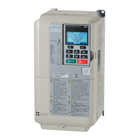
YASKAWA A1000 Technical Manual
High performance vector control drive
type: cimr-a series
models: 200 v class: 0.55 to 110 kw,
400 v class: 0.55 to 630 kw
Hide thumbs
Also See for A1000:
- Technical manual (544 pages) ,
- Quick start manual (358 pages) ,
- Installation manual (70 pages)
Table of Contents
Advertisement
Quick Links
YASKAWA AC Drive A1000
High Performance Vector Control Drive
Technical Manual
Type: CIMR-A
Models: 200 V Class: 0.55 to 110 kW
400 V Class: 0.55 to 630 kW
MANUAL NO. SIEP C710616 27G
1
1
Receiving
2
2
Mechanical Installation
3
3
Electrical Installation
Start-Up Programming &
4
4
Operation
5
5
Parameter Details
6
6
Troubleshooting
Periodic Inspection &
7
7
Maintenance
Peripheral Devices &
8
8
Options
A
A
Specifications
B
B
Parameter List
MEMOBUS/Modbus
C
C
Communications
D
D
Standards Compliance
E
E
Quick Reference Sheet
Advertisement
Chapters
Table of Contents
Troubleshooting

Related Manuals for YASKAWA A1000


Summary of Contents for YASKAWA A1000
- Page 1 YASKAWA AC Drive A1000 High Performance Vector Control Drive Technical Manual Type: CIMR-A Models: 200 V Class: 0.55 to 110 kW 400 V Class: 0.55 to 630 kW Receiving Mechanical Installation Electrical Installation Start-Up Programming & Operation Parameter Details Troubleshooting Periodic Inspection &...
- Page 2 YASKAWA. No patent liability is assumed with respect to the use of the information contained herein. Moreover, because YASKAWA is constantly striving to improve its high-quality products, the information contained in this manual is subject to change without notice.
- Page 3 Refer to Drive Alarms, Faults, and Errors on page 330 Refer to Troubleshooting without Fault Display on page 368. Standards Compliance Refer to on page 577. Refer to UL Standards on page 586. YASKAWA ELECTRIC SIEP C710616 27G YASKAWA AC Drive A1000 Technical Manual...
- Page 4 YASKAWA ELECTRIC SIEP C710616 27G YASKAWA AC Drive A1000 Technical Manual...
-
Page 5: Table Of Contents
A1000 Model Selection ........ - Page 6 Switching Between LOCAL and REMOTE ....... . . 106 YASKAWA ELECTRIC SIEP C710616 27G YASKAWA AC Drive A1000 Technical Manual...
- Page 7 C5: Automatic Speed Regulator (ASR) ........188 YASKAWA ELECTRIC SIEP C710616 27G YASKAWA AC Drive A1000 Technical Manual...
- Page 8 5.11 U: Monitor Parameters ..........319 YASKAWA ELECTRIC SIEP C710616 27G YASKAWA AC Drive A1000 Technical Manual...
- Page 9 Connected Machinery Vibrates When Motor Rotates ......370 YASKAWA ELECTRIC SIEP C710616 27G YASKAWA AC Drive A1000 Technical Manual...
- Page 10 A.1 Heavy Duty and Normal Duty Ratings ........436 YASKAWA ELECTRIC SIEP C710616 27G YASKAWA AC Drive A1000 Technical Manual...
- Page 11 YASKAWA SMRA Series SPM Motor ........
- Page 12 User Setting Table ........... 604 Index ..........................610 YASKAWA ELECTRIC SIEP C710616 27G YASKAWA AC Drive A1000 Technical Manual...
-
Page 13: Yaskawa Electric Siep C710616 27G Yaskawa Ac Drive A1000 Technical Manual
Revision History ......................624 YASKAWA ELECTRIC SIEP C710616 27G YASKAWA AC Drive A1000 Technical Manual... - Page 14 YASKAWA ELECTRIC SIEP C710616 27G YASKAWA AC Drive A1000 Technical Manual...
-
Page 15: I.1 Preface
Preface & General Safety This section provides safety messages pertinent to this product that, if not heeded, may result in fatality, personal injury, or equipment damage. YASKAWA is not responsible for the consequences of ignoring these instructions. PREFACE ............16 GENERAL SAFETY . -
Page 16: Applicable Documentation
YASKAWA must be promptly provided to the end user. YASKAWA offers an express warranty only as to the quality of its products in conforming to standards and specifications published in the YASKAWA manual. NO OTHER WARRANTY, EXPRESS OR IMPLIED, IS OFFERED. YASKAWA assumes no liability for any personal injury, property damage, losses, or claims arising from misapplication of its products. - Page 17 • When ordering a new copy of the manual due to damage or loss, contact your YASKAWA representative or the nearest YASKAWA sales office and provide the manual number shown on the front cover.
- Page 18 Do not attempt to modify or alter the drive in any way not explained in this manual. Failure to comply could result in death or serious injury. YASKAWA is not responsible for any modification of the product made by the user. This product must not be modified.
-
Page 19: I.2 General Safety
Crush Hazard Do not carry the drive by the front cover. Failure to comply may result in minor or moderate injury from the main body of the drive falling. YASKAWA ELECTRIC SIEP C710616 27G YASKAWA AC Drive A1000 Technical Manual... - Page 20 Failure to comply may cause damage to the electrical components in the drive. Do not pack the drive in wooden materials that have been fumigated or sterilized. Do not sterilize the entire package after the product is packed. YASKAWA ELECTRIC SIEP C710616 27G YASKAWA AC Drive A1000 Technical Manual...
-
Page 21: Application Notes
Fast Stop function is able to. Options The B1, B2, -, +1, +2, and +3 terminals are used to connect optional devices. Connect only A1000-compatible devices. Repetitive Starting/Stopping Cranes (hoists), elevators, punching presses, and other such applications with frequent starts and stops often exceed 150% of their rated current values. - Page 22 Selecting a Circuit Breaker or Leakage Circuit Breaker YASKAWA recommends installing equipment for residual current monitoring/detection (RCM/RCD) to the power supply side. The RCM/RCD should be designed for use with an AC drive (e.g. Type B according to IEC/EN 60755).
-
Page 23: Notes On Motor Operation
Vibration and Shock A1000 lets the user choose between high carrier PWM control and low carrier PWM. Selecting high carrier PWM can help reduce motor oscillation. • Take particular caution when using a variable speed drive for an application that is conventionally run from line power at a constant speed. -
Page 24: Applications With Specialized Motors
Contact YASKAWA or your YASKAWA agent if you plan to use a motor that does not fall within these specifications. • In Open Loop Vector Control for PM motors, braking torque is less than 125% when running between 20% to 100% speed, even with a braking resistor. -
Page 25: Drive Label Warnings
Ne Pas toucher. 危 険 けが.感電のおそれがあります。 ● ● 据え付け、 運転の前には必ず取扱説明書を読むこと。 ● 通電中および電源遮断後5分以内はフロントカバー ● を外さない事。 400V級インバータの場合は、電源の中性点が接地 ● ● されていることを確認すること。( 対応) ● 保守・点検、配線を行う場合は、出力側開閉器を 遮断後5分待って実施してください。 高温注意 インバータ上部、両側面は高温になります。 ● 触らないでください。 ● Figure i.3 Warning Information Position YASKAWA ELECTRIC SIEP C710616 27G YASKAWA AC Drive A1000 Technical Manual... -
Page 26: Warranty Information
Restrictions A1000 was not designed or manufactured for use in devices or systems that may directly affect or threaten human lives or health. Customers who intend to use the product described in this manual for devices or systems relating to transportation, health care, space aviation, atomic power, electric power, or in underwater applications must first contact their YASKAWA representatives or the nearest YASKAWA sales office. -
Page 27: Receiving
COMPONENT NAMES ..........35 YASKAWA ELECTRIC SIEP C710616 27G YASKAWA AC Drive A1000 Technical Manual... -
Page 28: Section Safety
Ensure that the motor is suitable for drive duty and/or the motor service factor is adequate to accommodate the additional heating with the intended operating conditions. YASKAWA ELECTRIC SIEP C710616 27G YASKAWA AC Drive A1000 Technical Manual... -
Page 29: General Description
<3> These values assume the carrier frequency is set to 2 kHz. Note: Current derating is required when setting the carrier frequency higher. Refer to Carrier Frequency Derating on page 446 details. YASKAWA ELECTRIC SIEP C710616 27G YASKAWA AC Drive A1000 Technical Manual... - Page 30 1.2 General Description Control Mode Selection Table 1.2 gives an overview of the A1000 control modes and their various features. Table 1.2 Control Modes and their Features Motor Type Induction Motors Permanent Magnet Motors Comments Control Mode V/f w/PG...
-
Page 31: General Description
Overvoltage during regeneration. Never use this Suppression function with hoist or crane applications. High Frequency YES (IPM Greatly increases the speed control range Injection motor) of an IPM motor. YASKAWA ELECTRIC SIEP C710616 27G YASKAWA AC Drive A1000 Technical Manual... -
Page 32: Model Number And Nameplate Check
Refer to Parameter Differences for models CIMR-A for details. <2> The address of the head office of YASKAWA Electric Corporation (responsible for product liability) is shown on the nameplate. Figure 1.1 Nameplate Information Model Number CIMR - A C 2... -
Page 33: Drive Models And Enclosure Types
Note: 1. Set C6-01 to select Normal duty and Heavy duty (default). 2. Refer to Drive Models and Enclosure Types on page 34 for differences regarding enclosure protection types and component descriptions. YASKAWA ELECTRIC SIEP C710616 27G YASKAWA AC Drive A1000 Technical Manual... -
Page 34: Drive Models And Enclosure Types
– 4A1200A <1> Removing the top protective cover from an IP20/NEMA 1, UL Type 1 enclosure drive voids NEMA 1, UL Type 1 protection but still keeps IP20 conformity. YASKAWA ELECTRIC SIEP C710616 27G YASKAWA AC Drive A1000 Technical Manual... -
Page 35: Component Names
CIMR-A4A0007F through 0011F. Drives CIMR-A2A0004F through 0012F and CIMR-A4A0002F through 0005F do not have a cooling fan or a cooling fan cover. Figure 1.2 Exploded View of IP20/NEMA 1, UL Type 1 Enclosure Components (CIMR-A2A0030F) YASKAWA ELECTRIC SIEP C710616 27G YASKAWA AC Drive A1000 Technical Manual... - Page 36 E – Drive Cover K – Cooling fan F – Front cover screw L – Fan cover G – Terminal cover Figure 1.3 Exploded View of IP00 Enclosure Components (CIMR-A2A0110A) YASKAWA ELECTRIC SIEP C710616 27G YASKAWA AC Drive A1000 Technical Manual...
-
Page 37: Component Names
E – USB port (type-B) F – Digital operator L – Heatsink G – Drive cover M – Mounting hole Figure 1.4 Exploded view of IP00 Enclosure Type Components (CIMR-A4A0165A) YASKAWA ELECTRIC SIEP C710616 27G YASKAWA AC Drive A1000 Technical Manual... -
Page 38: Ip00 Enclosure
H – Front cover screw <1> The following drive models come with a built-in circulation fan. CIMR-A2A0360, 2A0415 CIMR-A4A0362 Figure 1.5 Exploded view of IP00 Enclosure Type Components (CIMR-A4A0362A) YASKAWA ELECTRIC SIEP C710616 27G YASKAWA AC Drive A1000 Technical Manual... - Page 39 F – Drive cover 1 G – Drive cover 2 N – Heatsink H – Terminal cover O – Mounting hole Figure 1.6 Exploded view of IP00 Enclosure Type Components (CIMR-A4A0414A) YASKAWA ELECTRIC SIEP C710616 27G YASKAWA AC Drive A1000 Technical Manual...
- Page 40 N – Heatsink G – Drive cover 2 O – Fan guard H – Terminal cover P – Mounting hole Figure 1.7 Exploded view of IP00 Enclosure Type Components (CIMR-A4A0515A, 0675A) YASKAWA ELECTRIC SIEP C710616 27G YASKAWA AC Drive A1000 Technical Manual...
- Page 41 R – Heatsink J – Drive cover 1 S – Fan guard K – Drive cover 2 T – Mounting hole Figure 1.8 Exploded view of IP00 Enclosure Type Components (CIMR-A4A0930A) YASKAWA ELECTRIC SIEP C710616 27G YASKAWA AC Drive A1000 Technical Manual...
-
Page 42: Front Views
M – Option card connector (CN5-B) G – Jumper S3 (Refer to Sinking/Sourcing N – Option card connector (CN5-A) Mode Selection for Safe Disable Inputs on page Figure 1.9 Front View of Drives YASKAWA ELECTRIC SIEP C710616 27G YASKAWA AC Drive A1000 Technical Manual... -
Page 43: Mechanical Installation
MECHANICAL INSTALLATION ........46 YASKAWA ELECTRIC SIEP C710616 27G YASKAWA AC Drive A1000 Technical Manual... -
Page 44: Section Safety
Do not attempt to flip the drive over or leave the drive unattended while it is suspended by the wires. Failure to comply may result in serious injury or death from falling equipment. YASKAWA ELECTRIC SIEP C710616 27G YASKAWA AC Drive A1000 Technical Manual... - Page 45 This is also applicable when an existing explosion-proof motor is to be operated with the drive. Since the drive itself is not explosion-proof, always install it in a safe place. Never lift the drive up while the cover is removed. This can damage the terminal board and other components. YASKAWA ELECTRIC SIEP C710616 27G YASKAWA AC Drive A1000 Technical Manual...
- Page 46 Installation Orientation and Spacing Install the drive upright as illustrated in Figure 2.1 to maintain proper cooling. Figure 2.1 Figure 2.1 Correct Installation Orientation YASKAWA ELECTRIC SIEP C710616 27G YASKAWA AC Drive A1000 Technical Manual...
- Page 47 Note: When installing drives of different heights in the same enclosure panel, the tops of the drives should line up. Leave space between the top and bottom of stacked drives for easy cooling fan replacement if required. YASKAWA ELECTRIC SIEP C710616 27G YASKAWA AC Drive A1000 Technical Manual...
-
Page 48: Mechanical Installation
A – No space between drive and washer C – Space between drive and washer B – Spring washer: Fully closed D – Spring washer: Open Figure 2.5 Details of Spring Washers YASKAWA ELECTRIC SIEP C710616 27G YASKAWA AC Drive A1000 Technical Manual... - Page 49 When ready to install the drive in the enclosure panel, lower the drive. Halt lowing once when the drive has reached near the floor, and then lower the drive again very slowly. YASKAWA ELECTRIC SIEP C710616 27G YASKAWA AC Drive A1000 Technical Manual...
-
Page 50: Digital Operator Remote Usage
The digital operator is flush Installation Support Set B with the outside of the panel. Phillips screwdriver (#1) (for use with threaded studs that are EZZ020642B Wrench (7 mm) fixed to the panel) YASKAWA ELECTRIC SIEP C710616 27G YASKAWA AC Drive A1000 Technical Manual... - Page 51 Unit: mm Figure 2.12 Panel Cut-Out Dimensions (External/Face-Mount Installation) Internal/Flush-Mount An internal flush-mount requires an installation support set that must be purchased separately. Contact your YASKAWA representative to order an installation support set and mounting hardware. Figure 2.13 illustrates how to attach the Installation Support Set A.
-
Page 52: Exterior And Mounting Dimensions
2A0069F 4A0038F 2A0081F 4A0044F 4A0058A 4A0072A 4A0088A 4A0103A 2A0110A 4A0139A 2A0138A 4A0165A 2A0169A 4A0208A 2A0211A IP00 Enclosure 4A0250A 2A0250A 4A0296A 2A0312A 4A0362A 2A0360A 4A0414A 2A0415A 4A0515A 4A0675A 4A0930A 4A1200A YASKAWA ELECTRIC SIEP C710616 27G YASKAWA AC Drive A1000 Technical Manual... - Page 53 – 0009 – – – 0011 – – – 0018 – – – 0023 – – – 0031 – – – 0038 – – – 0044 – – – YASKAWA ELECTRIC SIEP C710616 27G YASKAWA AC Drive A1000 Technical Manual...
- Page 54 2.2 Mechanical Installation IP00 Enclosure Drives Max W2 Max W2 Figure 1 Max W2 Max W2 Figure 2 Max W2 Max W2 Figure 3 YASKAWA ELECTRIC SIEP C710616 27G YASKAWA AC Drive A1000 Technical Manual...
- Page 55 – – 0296 – – 0362 – – 0414 – – 0515 1140 – 1110 0675 1140 – 1110 0930 1250 1380 1110 1345 1200 1250 1380 1110 1345 YASKAWA ELECTRIC SIEP C710616 27G YASKAWA AC Drive A1000 Technical Manual...
- Page 56 2.2 Mechanical Installation YASKAWA ELECTRIC SIEP C710616 27G YASKAWA AC Drive A1000 Technical Manual...
- Page 57 3.13 WIRING CHECKLIST ..........94 YASKAWA ELECTRIC SIEP C710616 27G YASKAWA AC Drive A1000 Technical Manual...
-
Page 58: Section Safety
Before wiring terminals, disconnect all power to the equipment. The internal capacitor remains charged even after the power supply is turned off. After shutting off the power, wait for at least the amount of time specified on the drive before touching any components. YASKAWA ELECTRIC SIEP C710616 27G YASKAWA AC Drive A1000 Technical Manual... - Page 59 Do not modify the drive circuitry. Failure to comply could result in damage to the drive and will void warranty. YASKAWA is not responsible for any modification of the product made by the user. This product must not be modified.
-
Page 60: Standard Connection Diagram
NOTICE: Correctly set the Sinking/sourcing mode selection jumper S3 (internal/external power supply). Failure to comply could result in damage to the drive. Refer to Control I/O Connections on page 88 for details. Figure 3.1 YASKAWA ELECTRIC SIEP C710616 27G YASKAWA AC Drive A1000 Technical Manual... - Page 61 SN as doing so will damage the drive. (see Sinking/Sourcing Mode for Digital Inputs on page <6> The maximum current supplied by this voltage source is 150 mA if no digital input option card DI-A3 is used. YASKAWA ELECTRIC SIEP C710616 27G YASKAWA AC Drive A1000 Technical Manual...
-
Page 62: Standard Connection Diagram
NOTICE: Do not connect more than one multi-function input to one terminal. Improper wiring may result in drive malfunction. Use an external power supply when sharing a terminal with more than one input. Do not use the built-in +24 V power supply. YASKAWA ELECTRIC SIEP C710616 27G YASKAWA AC Drive A1000 Technical Manual... -
Page 63: Main Circuit Configurations
Supply CIMR-A4A0930, 4A1200 <1> Relay Current reactor sensor R/L1 U/T1 S/L2 V/T2 T/L3 W/T3 R1/L11 S1/L21 T1/L31 – 24 V Control Power Gate board Operator board Supply YASKAWA ELECTRIC SIEP C710616 27G YASKAWA AC Drive A1000 Technical Manual... - Page 64 • Models CIMR-A4A0930 and 4A1200 are shipped from the factory with jumpers short-circuiting terminals R/L1-R1/L11, S/L2-S1/L21, and T/L3-T1/L31. Figure 3.3 Jumper S1/L21 R1/L11 T1/L31 R/L1 T/L3 S/L2 Figure 3.2 Removing the jumper YASKAWA ELECTRIC SIEP C710616 27G YASKAWA AC Drive A1000 Technical Manual...
-
Page 65: Main Circuit Configurations
Figure 3.4 Braking Resistor Unit (option) Braking Unit (option) − − U/T1 R/L1 V/T2 Motor S/L2 W/T3 T/L3 W2 V2 U2 R1/L11 S1/L21 T1/L31 Figure 3.3 Connecting Main Circuit Terminals YASKAWA ELECTRIC SIEP C710616 27G YASKAWA AC Drive A1000 Technical Manual... -
Page 66: Terminal Block Configuration
– R/L1 S/L2 T/L3 V/T2 W/T3 U/T1 CIMR-A 2A0169, 0211, 0250, 0312, 0360, 0415 <1> CIMR-A 4A0139, 0165, 0208, 0250, 0296, 0362 – R/L1 S/L2 T/L3 U/T1 V/T2 W/T3 YASKAWA ELECTRIC SIEP C710616 27G YASKAWA AC Drive A1000 Technical Manual... -
Page 67: Terminal Block Configuration
R1/L11 S1/L21 T1/L31 R/L1 S/L2 T/L3 U/T1 V/T2 W/T3 <1> Terminal block design differs slightly for models CIMR-A2A0250 through 2A0415 and 4A0208 through 4A0362. Figure 3.4 Main Circuit Terminal Block Configuration YASKAWA ELECTRIC SIEP C710616 27G YASKAWA AC Drive A1000 Technical Manual... -
Page 68: Terminal Cover
Power lines and signal wiring exit through the opening provided. Figure 3.7 Reattaching the Terminal Cover on an IP20/NEMA 1, UL Type 1 Enclosure Drive YASKAWA ELECTRIC SIEP C710616 27G YASKAWA AC Drive A1000 Technical Manual... -
Page 69: Terminal Cover
Figure 3.13 Connect ground wiring first, followed by the main circuit, and then wire the control circuit. Figure 3.10 Reattaching the Terminal Cover on an IP00 Enclosure Drive YASKAWA ELECTRIC SIEP C710616 27G YASKAWA AC Drive A1000 Technical Manual... -
Page 70: Digital Operator And
Figure 3.16 Figure 3.13 Remove the Front Cover (2A0004 to 2A0081 and 4A0002 to 4A0044) YASKAWA ELECTRIC SIEP C710616 27G YASKAWA AC Drive A1000 Technical Manual... -
Page 71: Digital Operator And Front Cover
First unhook the left side of the front cover, then swing the left side towards you as shown in the figure below until the cover comes off. Figure 3.18 Figure 3.15 Remove the Front Cover (2A0110 to 2A0415 and 4A0058 to 4A1200) YASKAWA ELECTRIC SIEP C710616 27G YASKAWA AC Drive A1000 Technical Manual... - Page 72 Figure 3.16 Reattach the Front Cover (2A0110 to 2A0415 and 4A0058 to 4A1200) Once the hooks have connected to the drive, press firmly on the cover to make sure it locks into place. YASKAWA ELECTRIC SIEP C710616 27G YASKAWA AC Drive A1000 Technical Manual...
- Page 73 3.6 Digital Operator and Front Cover YASKAWA ELECTRIC SIEP C710616 27G YASKAWA AC Drive A1000 Technical Manual...
-
Page 74: Top Protective Cover
Pinch the hooks inward so that the they connect with the mounting holes and fasten the top protective cover back into place. Figure 3.21 Top Protective Cover Mounting Holes Figure 3.18 Reattaching the Top Protective Cover YASKAWA ELECTRIC SIEP C710616 27G YASKAWA AC Drive A1000 Technical Manual... -
Page 75: Main Circuit Wiring
NOTICE: If a fuse is blown or an equipment for residual current monitoring/detection (RCM/RCD) is tripped, check the wiring and the selection of the peripheral devices to identify the cause. Contact YASKAWA before restarting the drive or the peripheral devices if the cause cannot be identified. -
Page 76: Protecting Main Circuit Terminals
Crimp Terminal Size on page 591 for closed-loop crimp terminal recommendations. The wire gauges listed in the following tables are YASKAWA recommendations. Refer to local codes for proper wire gauge selections. YASKAWA ELECTRIC SIEP C710616 27G YASKAWA AC Drive A1000 Technical Manual... - Page 77 U/T1, V/T2, W/T3 35 to 70 18 to 23 (159 to 204) –, +1 – 50 to 70 2A0138 B1, B2 – 25 to 70 9.0 to 11 (79.7 to 97.4) YASKAWA ELECTRIC SIEP C710616 27G YASKAWA AC Drive A1000 Technical Manual...
- Page 78 Note: When connecting peripheral devices and options to the terminals –, +1, +3, B1, and B2, refer to the instruction manuals for each devices. For more information, contact YASKAWA or your nearest sales representative. YASKAWA ELECTRIC SIEP C710616 27G YASKAWA AC Drive A1000 Technical Manual...
- Page 79 16 to 50 U/T1, V/T2, W/T3 16 to 50 9.0 to 11 –, +1 – 25 to 50 4A0072 (79.7 to 97.4) B1, B2 – 16 to 50 16 to 25 YASKAWA ELECTRIC SIEP C710616 27G YASKAWA AC Drive A1000 Technical Manual...
- Page 80 150 2P U/T1, V/T2, W/T3 95 to 150 32 to 40 –, +1 – 70 to 150 4A0515 (283 to 354) – 70 to 150 50 to 150 YASKAWA ELECTRIC SIEP C710616 27G YASKAWA AC Drive A1000 Technical Manual...
-
Page 81: Main Circuit Terminal And Motor Wiring
Note: 1. When setting carrier frequency in a drive running multiple motors, calculate the cable length as the total distance of wiring to all motors that are connected. 2. The maximum cable length is 100 m when using OLV/PM (A1-02 = 5) or AOLV/PM (A1-02 = 6). YASKAWA ELECTRIC SIEP C710616 27G YASKAWA AC Drive A1000 Technical Manual... - Page 82 Improper wiring connections could cause the braking resistor to overheat and cause death or serious injury by fire. Failure to comply may result in damage to the braking circuit or drive. YASKAWA ELECTRIC SIEP C710616 27G YASKAWA AC Drive A1000 Technical Manual...
-
Page 83: Control Circuit Wiring
Use DIP switch S4 on the terminal board to selection between analog or PTC input. Frequency reference common E (G) Ground for shielded lines and option cards – – YASKAWA ELECTRIC SIEP C710616 27G YASKAWA AC Drive A1000 Technical Manual... -
Page 84: Terminal Configuration
D – Terminal Block (TB 3) B – Terminal Block (TB 5) E – Terminal Block (TB 4) C – Terminal Block (TB 1) Figure 3.22 Control Circuit Terminal Arrangement YASKAWA ELECTRIC SIEP C710616 27G YASKAWA AC Drive A1000 Technical Manual... -
Page 85: Wiring The Control Circuit Terminal
(4.4 to 8.9) (12) (20 to 14) Ferrule-Type Wire Terminals YASKAWA recommends using CRIMPFOX 6, a crimping tool manufactured by PHOENIX CONTACT, to prepare wire ends with insulated sleeves before connecting to the drive. See Table 3.11 for dimensions. Figure 3.26 Figure 3.23 Ferrule Dimensions... - Page 86 NOTICE: The analog signal wiring between the drive and the operator station or peripheral equipment should not exceed 50 meters when using an analog signal from a remote source to supply the frequency reference. Failure to comply could result in poor system performance. YASKAWA ELECTRIC SIEP C710616 27G YASKAWA AC Drive A1000 Technical Manual...
-
Page 87: Switches And Jumpers On The Terminal Board
RS-422/485 Termination Resistor Figure 3.27 Locations of Jumpers and Switches on the Terminal Board <1> Available slide switch S6 is models ETC740310 and ETC740311. N.O. N.O. N.C. N.C. ETC740310 ETC740311 YASKAWA ELECTRIC SIEP C710616 27G YASKAWA AC Drive A1000 Technical Manual... -
Page 88: Control I/O Connections
Table 3.13 Safe Disable Input Sink / Source / External Power Supply Selection Drive Internal Power Supply External 24 Vdc Power Supply Jumper S3 Jumper S3 24 Vdc 24 Vdc External 24 Vdc ±10% Sinking Mode YASKAWA ELECTRIC SIEP C710616 27G YASKAWA AC Drive A1000 Technical Manual... -
Page 89: Using The Pulse Train Output
Load Impedance (k) 12 to 15 Vdc 10% 1.0 k or higher Figure 3.32 External Power Supply Load Impedance Sink Current Figure 3.29 Pulse Output Connection Using External Voltage Supply YASKAWA ELECTRIC SIEP C710616 27G YASKAWA AC Drive A1000 Technical Manual... -
Page 90: Terminal A2 Input Signal Selection
Terminal AM signal level selection 0: 0 to 10 Vdc 1: -10 to 10 Vdc 0 to 2 H4-08 Terminal FM signal level selection 2: 4 to 20 mA YASKAWA ELECTRIC SIEP C710616 27G YASKAWA AC Drive A1000 Technical Manual... -
Page 91: Memobus/Modbus Termination
Table 3.20 EDM Switch Settings S6 Position Description N.O. Normal Open N.C. Normal Close (default setting) Note: Refer to Safe Disable Input Function on page 600 for details on EDM. YASKAWA ELECTRIC SIEP C710616 27G YASKAWA AC Drive A1000 Technical Manual... -
Page 92: Connect To A Pc
The drive can connect to the USB port of a PC using a USB 2.0, AB type cable (sold separately). DriveWizard Plus can then be used to monitor drive performance and manage parameter settings. Contact YASKAWA for more information on DriveWizard Plus. -
Page 93: External Interlock
Ready 1 Operation Ready Drive 2 Controller Relay 1 Relay 1 Fault 2 Fault 250 Vac Output Relay 2 Relay 2 Ready 2 Operation Ready Figure 3.31 Interlock Circuit Example YASKAWA ELECTRIC SIEP C710616 27G YASKAWA AC Drive A1000 Technical Manual... -
Page 94: Wiring Checklist
Refer to Wire Gauges and Tightening Torque on page Pick up all wire clippings. – Ensure that no frayed wires on the terminal block are touching other terminals or connections. – YASKAWA ELECTRIC SIEP C710616 27G YASKAWA AC Drive A1000 Technical Manual... - Page 95 Properly separate control circuit wiring and main circuit wiring. – Analog signal line wiring should not exceed 50 m. – Safe Disable input wiring should not exceed 30 m. – YASKAWA ELECTRIC SIEP C710616 27G YASKAWA AC Drive A1000 Technical Manual...
- Page 96 3.13 Wiring Checklist YASKAWA ELECTRIC SIEP C710616 27G YASKAWA AC Drive A1000 Technical Manual...
-
Page 97: Start-Up Programming & Operation
4.11 TEST RUN CHECKLIST ..........139 YASKAWA ELECTRIC SIEP C710616 27G YASKAWA AC Drive A1000 Technical Manual... -
Page 98: Section Safety
Precautions should be taken on the machine side in crane and hoist applications to ensure that load does not fall or slip. Failure to take proper safety precautions can result in serious injury. YASKAWA ELECTRIC SIEP C710616 27G YASKAWA AC Drive A1000 Technical Manual... -
Page 99: Using The Digital Operator
<2> The LO/RE key can only switch between LOCAL and REMOTE when the drive is stopped. To disable the LO/RE key to prohibit switching between LOCAL and REMOTE, set parameter o2-01 to 0. YASKAWA ELECTRIC SIEP C710616 27G YASKAWA AC Drive A1000 Technical Manual... -
Page 100: Lcd Display
RESET Pressing resets the existing drive fault or error. <1> Displayed when in Frequency Reference Mode. <2> Displayed when in Frequency Reference Mode and Monitor Mode. YASKAWA ELECTRIC SIEP C710616 27G YASKAWA AC Drive A1000 Technical Manual... -
Page 101: Alarm (Alm) Led Displays
Figure 4.3 RUN LED Status and Meaning Figure 4.4 Drive output frequency during stop STOP STOP 6 Hz 0 Hz Frequency setting RUN LED Flashing Figure 4.4 RUN LED and Drive Operation YASKAWA ELECTRIC SIEP C710616 27G YASKAWA AC Drive A1000 Technical Manual... -
Page 102: Menu Structure For Digital Operator
X characters are shown in this manual. The LCD Operator will display the actual setting values. <5> The Frequency Reference appears after the initial display which shows the product name. <6> The information that appears on the display will vary depending on the drive. YASKAWA ELECTRIC SIEP C710616 27G YASKAWA AC Drive A1000 Technical Manual... -
Page 103: The Drive And Programming Modes
Refer to Parameter Table on page 453. Mode HELP DATA - MODE - Auto-Tuning Auto-Tuning Mode Motor parameters are calculated and set automatically. Refer to Auto-Tuning on page 120. AUTO Programming Mode HELP DATA YASKAWA ELECTRIC SIEP C710616 27G YASKAWA AC Drive A1000 Technical Manual... - Page 104 • Setup Group: Access a list of commonly used parameters to simplify setup (see Simplified Setup Using the Setup Group on page 107) • Auto-Tuning Mode: Automatically calculates and sets motor parameters to optimize drive performance YASKAWA ELECTRIC SIEP C710616 27G YASKAWA AC Drive A1000 Technical Manual...
-
Page 105: Changing Parameter Settings Or Values
The display automatically returns to the screen shown in Step 4. (0.0~6000.0) “10.0 sec” ← → - MODE - FREF (OPR) U1-01= 0.00Hz Press the key until back at the initial display. U1-02= 0.00Hz LSEQ U1-03= 0.00A LREF FWD/REV YASKAWA ELECTRIC SIEP C710616 27G YASKAWA AC Drive A1000 Technical Manual... -
Page 106: Verifying Parameter Changes: Verify Menu
C1-02 appears. “10.0sec” Home DATA - VERIFY - PRG Accel Time 1 C1-01=0020.0sec Press the key to access the setting value. Left digit flashes. (0.0~6000.0) “10.0sec” Home DATA YASKAWA ELECTRIC SIEP C710616 27G YASKAWA AC Drive A1000 Technical Manual... -
Page 107: Simplified Setup Using The Setup Group
<1> Use the up and down arrow keys to scroll through the Setup Group. Press the ENTER key to view or change parameter settings. <2> To return to the previous menu without saving changes, press the ESC key. Figure 4.7 Setup Group Example YASKAWA ELECTRIC SIEP C710616 27G YASKAWA AC Drive A1000 Technical Manual... -
Page 108: Switching Between Local And Remote
(set the corresponding parameter H1- to “1”). Setting H1- to 1 disables the LO/RE key on the digital operator. Refer to H1: Multi-Function Digital Inputs on page 482 for details. YASKAWA ELECTRIC SIEP C710616 27G YASKAWA AC Drive A1000 Technical Manual... -
Page 109: Start-Up Flowcharts
2. Auto-Tuning should be performed again after installing an AC reactor or other such components to the output side of the drive. YASKAWA ELECTRIC SIEP C710616 27G YASKAWA AC Drive A1000 Technical Manual... -
Page 110: Subchart A-1: Simple Motor Setup Using V/F Control
Couple the load or machine to the motor. Run the machine and check for desired operation. Return to Flowchart Figure 4.9 Simple Motor Setup with Energy Savings or Speed Search YASKAWA ELECTRIC SIEP C710616 27G YASKAWA AC Drive A1000 Technical Manual... -
Page 111: Subchart A-2: High Performance Operation Using Olv Or Clv
<5> ASR Gain Tuning automatically performs Inertia Tuning and sets parameters related to Feed Forward and the KEB Ride-Thru function. Figure 4.10 Flowchart A2: High Performance Operation Using OLV or CLV YASKAWA ELECTRIC SIEP C710616 27G YASKAWA AC Drive A1000 Technical Manual... -
Page 112: Subchart A-3: Operation With Permanent Magnet Motors
Return to Flowchart <1> A motor code can be entered as the parameter setting for E5-01 when using a YASKAWA PM motor (SMRA Series, SSR1 Series, and SST4 Series). If using a motor from another manufacturer, enter FFFF. <2> Make sure the motor and load can run freely, i.e., if a brake is mounted, make sure it is released. -
Page 113: Powering Up The Drive
Data displayed varies by the type of fault. Refer to Fault Displays, Causes, and Possible Solutions on page 336 Fault for more information and possible solution. are lit. Ext Fault S3 RESET External fault (example) YASKAWA ELECTRIC SIEP C710616 27G YASKAWA AC Drive A1000 Technical Manual... -
Page 114: Application Selection
Multi-Function Digital Input Terminal S6 Function Selection C1-02 Deceleration Time 1 H1-07 Multi-Function Digital Input Terminal S7 Function Selection E1-03 V/f Pattern Selection L5-01 Number of Auto Restart Attempts E1-07 Mid Output Frequency YASKAWA ELECTRIC SIEP C710616 27G YASKAWA AC Drive A1000 Technical Manual... -
Page 115: Setting 2: Conveyor Application
Deceleration Time 1 H3-12 Terminal A2 Input Bias C6-02 Carrier Frequency Selection L2-01 Momentary Power Loss Operation Selection d2-01 Frequency Reference Upper Limit o4-12 kWh Monitor Initial Value Selection YASKAWA ELECTRIC SIEP C710616 27G YASKAWA AC Drive A1000 Technical Manual... -
Page 116: Setting 5: Compressor Application
Motor Overload Protection Selection C1-02 Deceleration Time 1 L4-01 Speed Agreement Detection Level C6-02 Carrier Frequency Selection L6-02 Torque Detection Level 1 d1-01 Frequency Reference 1 L6-03 Torque Detection Time 1 YASKAWA ELECTRIC SIEP C710616 27G YASKAWA AC Drive A1000 Technical Manual... -
Page 117: Notes On Controlling The Brake When Using The Hoist Application Preset
Controlling the Brake in Closed Loop Vector Control For hoist applications using Closed Loop Vector Control, YASKAWA recommends setting the “During frequency output” signal to a digital output (H2-01 = 37 for terminal M1-M2) in order to control the brake. This way, the brake will always close during baseblock, and the setting of parameter L4-07 as described above will not affect brake control. - Page 118 Holding brake Open Closed Closed <1> The drive brakes at the frequency set to b2-01 or E1-09, whichever value is higher. Figure 4.15 Holding Brake Time Chart (CLV, CLV/PM) YASKAWA ELECTRIC SIEP C710616 27G YASKAWA AC Drive A1000 Technical Manual...
-
Page 119: Setting 7: Traveling Application
C6-02 Carrier Frequency Selection H1-06 Multi-Function Digital Input Terminal S6 Function d1-01 Frequency Reference 1 H2-01 Terminals M1-M2 Function Selection d1-02 Frequency Reference 2 L1-01 Motor Overload Protection Selection YASKAWA ELECTRIC SIEP C710616 27G YASKAWA AC Drive A1000 Technical Manual... -
Page 120: Auto-Tuning
2, 3 2, 3 Motor rated power T1-02 Motor rated voltage T1-03 Motor rated current T1-04 Motor rated frequency T1-05 Number of motor poles T1-06 – Motor rated Speed T1-07 YASKAWA ELECTRIC SIEP C710616 27G YASKAWA AC Drive A1000 Technical Manual... - Page 121 Subchart A-3: Operation with Permanent Magnet Motors on page 112 for details on the tuning mode selection and the tuning process. Figure 4.15 Figure 4.16 Example of Motor Nameplate YASKAWA ELECTRIC SIEP C710616 27G YASKAWA AC Drive A1000 Technical Manual...
- Page 122 <2> <2> <2> (mech.) <1> Input the motor code when using the YASKAWA motor. Select FFFF when using the motor by other manufacturers. <2> Input data is needed for CLV/PM only. <3> Depends on T2-13 setting. Inertia Tuning and Speed Control Loop Auto-Tuning Inertia Tuning can be performed when the drive is using Closed Loop Vector control for either IM or PM motors.
-
Page 123: Before Auto-Tuning The Drive
WARNING! Sudden Movement Hazard. If installed, do not release the mechanical brake during stationary Auto-Tuning. Inadvertent brake release may cause damage to equipment or injury to personnel. Ensure that the mechanical brake release circuit is not controlled by the drive multi-function digital outputs. YASKAWA ELECTRIC SIEP C710616 27G YASKAWA AC Drive A1000 Technical Manual... - Page 124 • Ensure the motor-mounted brake is fully released if installed. • Connected machinery should be allowed to rotate the motor. YASKAWA ELECTRIC SIEP C710616 27G YASKAWA AC Drive A1000 Technical Manual...
-
Page 125: Auto-Tuning Interruption And Fault Codes
Standard Tuning DATA <1> T1-00 will appear on the display when one of the multi-function inputs has been set to switch between motor 1 and motor 2 (H1- = 16). YASKAWA ELECTRIC SIEP C710616 27G YASKAWA AC Drive A1000 Technical Manual... - Page 126 Note: 1. For details on each setting, Refer to Parameter Settings during Induction Motor Auto-Tuning: T1 on page 127. 2. To execute Stationary Auto-Tuning for line-to-line resistance only, set parameters T1-02 and T1-04. YASKAWA ELECTRIC SIEP C710616 27G YASKAWA AC Drive A1000 Technical Manual...
-
Page 127: Parameter Settings During Induction Motor Auto-Tuning: T1
Auto-Tuning automatically sets parameters E1- and E2- for motor 1. Setting 2: Motor 2 Auto-Tuning automatically sets parameters E3- and E4- for motor 2. Make sure that motor 2 is connected to the drive for Auto-Tuning. YASKAWA ELECTRIC SIEP C710616 27G YASKAWA AC Drive A1000 Technical Manual... - Page 128 E1-04 (E3-04 for motor 2) after Auto-Tuning is complete. Name Setting Range Default T1-05 Motor Base Frequency 0.0 to 400.0 Hz 50.0 Hz YASKAWA ELECTRIC SIEP C710616 27G YASKAWA AC Drive A1000 Technical Manual...
- Page 129 T1-10: Motor Rated Slip (T1-01 = 4, 5) Sets the rated slip for the motor. The default setting displayed is the motor rated slip for a YASKAWA motor calculated from the output power set in T1-02. Enter the data listed on the motor test report.
-
Page 130: Parameter Settings During Pm Motor Auto-Tuning: T2
T2-02: PM Motor Code Selection If the drive is operating a YASKAWA PM motor from the SMRA, SSR1, or SST4 series, enter the motor code for the motor in parameter T2-02. This will automatically set parameters T2-03 through T2-09. Use the motor nameplate or motor test report values to set parameters T2-10 to T2-14. - Page 131 T2-12: PM Motor q-Axis Inductance Enter the q axis inductance per motor phase. Name Setting Range Default T2-12 PM Motor q-Axis Inductance 0.00 to 600.00 mH Depending on T2-02 YASKAWA ELECTRIC SIEP C710616 27G YASKAWA AC Drive A1000 Technical Manual...
-
Page 132: Parameter Settings During Inertia And Speed Control Loop Auto-Tuning: T3
C5-17 (C5-37) Motor Inertia C5-18 (C5-38) Motor Inertia Ratio L3-24 Motor Acceleration Time for Inertia Calculations L3-25 Load Inertia Ratio n5-02 Motor Acceleration Time n5-03 Feed Forward Control Ratio Gain YASKAWA ELECTRIC SIEP C710616 27G YASKAWA AC Drive A1000 Technical Manual... - Page 133 T3-03: Motor Inertia Enter the inertia of the motor. This value is used to determine the load inertia using the test signal response. The default setting is for a YASKAWA standard motor as listed in the motor inertia table. Name...
-
Page 134: No-Load Operation Test Run
10 Hz, verifying smooth operation at all speeds. For each frequency, check the drive output current using monitor U1-03. The current should be well below the motor rated current. YASKAWA ELECTRIC SIEP C710616 27G YASKAWA AC Drive A1000 Technical Manual... - Page 135 LSEQ U1-03= 0.00A LREF FWD/REV STOP The drive should operate normally. Press to stop the motor. RUN flashes until the motor comes to a RESET ENTER complete stop. STOP YASKAWA ELECTRIC SIEP C710616 27G YASKAWA AC Drive A1000 Technical Manual...
-
Page 136: Test Run With Load Connected
• Correct any problems that occur with hunting, oscillation, or other control-related issues. Refer to Motor Performance Fine-Tuning on page 326 for details. YASKAWA ELECTRIC SIEP C710616 27G YASKAWA AC Drive A1000 Technical Manual... -
Page 137: Verifying Parameter Settings And Backing Up Changes
A1-05: A1-01, A1-02, A1-03, A1-06, A1-07, and A2-01 through A2-32. Note: Parameter A1-05 is hidden from view. To display A1-05, access parameter A1-04 and simultaneously press the key and the key. YASKAWA ELECTRIC SIEP C710616 27G YASKAWA AC Drive A1000 Technical Manual... -
Page 138: Copy Function
DriveWizard is a PC software tool for parameter management, monitoring, and diagnosis. DriveWizard can load, store, and copy drive parameter settings. For details, refer to Help in the DriveWizard software. YASKAWA ELECTRIC SIEP C710616 27G YASKAWA AC Drive A1000 Technical Manual... -
Page 139: Test Run Checklist
Set the proportional gain for ASR speed control to C5-01 and the integral time to C5-02. Perform ASR Tuning if possible. Set F1-01 and F1-05. 225, Set the offset between the rotor magnetic axis and the Z-pulse of the encoder connected to E5-11. YASKAWA ELECTRIC SIEP C710616 27G YASKAWA AC Drive A1000 Technical Manual... - Page 140 Bias adjustment: Set the minimum voltage/current signal and adjust the analog input bias (H3-04 for input A1, H3-12 for input A2, H3-08 for analog input A3) until the frequency reference value reaches the desired minimum value. YASKAWA ELECTRIC SIEP C710616 27G YASKAWA AC Drive A1000 Technical Manual...
-
Page 141: Parameter Details
5.11 U: MONITOR PARAMETERS........321 YASKAWA ELECTRIC SIEP C710616 27G YASKAWA AC Drive A1000 Technical Manual... -
Page 142: A: Initialization
• If parameters are changed via serial communication, then it will not be possible to edit or change parameters settings with the drive’s digital operator until an Enter command is issued to the drive from the serial communication. YASKAWA ELECTRIC SIEP C710616 27G YASKAWA AC Drive A1000 Technical Manual... - Page 143 S1 and S2 configured as Forward run and Reverse run, respectively. For more on digital input functions, refer to Setting 40, 41: Forward run, Reverse run command for 2-wire sequence on page 242. YASKAWA ELECTRIC SIEP C710616 27G YASKAWA AC Drive A1000 Technical Manual...
- Page 144 Turn on the power to the drive. The initial display appears. U1-02= 0.00Hz LSEQ U1-03= 0.00A LREF FWD/REV - MODE - Programming Press the key until the Parameter Setting Mode screen appears. HELP DATA YASKAWA ELECTRIC SIEP C710616 27G YASKAWA AC Drive A1000 Technical Manual...
- Page 145 Table 5.4 Enter the Password to Unlock Parameters (continuing from step 3 above) Step Display/Result -PRMSET- Initialization A1-00= Press to enter the parameter setup display. Select Language ← → YASKAWA ELECTRIC SIEP C710616 27G YASKAWA AC Drive A1000 Technical Manual...
- Page 146 User Parameters, A2-01 through A2-16. These can be edited more easily in the Setup Mode and provide quicker access by eliminating the need to scroll through multiple menus. Refer to Application Selection on page 114 for details on parameter A1-06. YASKAWA ELECTRIC SIEP C710616 27G YASKAWA AC Drive A1000 Technical Manual...
-
Page 147: A2: User Parameters
Note: 1. If DriveWorksEZ has assigned functions to any multi-function output terminals, those functions will remain set to those terminals even after disabling DriveWorksEZ. 2. For more information on DriveWorksEZ, contact a YASKAWA representative or the YASKAWA sales department directly. Parameter Name... -
Page 148: B: Application
Figure 5.1 Setting the Frequency Reference as a Voltage Signal at Terminal A1 Use the wiring example shown in Figure 5.1 for any other analog input terminals. When using input A2 make sure DIP switch S1 is set for voltage input. YASKAWA ELECTRIC SIEP C710616 27G YASKAWA AC Drive A1000 Technical Manual... - Page 149 • Set the pulse input scaling H6-02 to the pulse train frequency value that equals 100% of the frequency reference. • Enter a pulse train signal to terminal RP and check if the correct frequency reference is displayed. YASKAWA ELECTRIC SIEP C710616 27G YASKAWA AC Drive A1000 Technical Manual...
- Page 150 When the output frequency falls below the level set in parameter b2-01, the drive will start DC injection, Zero Speed Control or Short Circuit Braking, depending on the selected control mode. YASKAWA ELECTRIC SIEP C710616 27G YASKAWA AC Drive A1000 Technical Manual...
- Page 151 DC Injection at start (refer to b2-03: DC Injection Braking Time at Start on page 159) or Speed Search (refer to b3: Speed Search on page 160). YASKAWA ELECTRIC SIEP C710616 27G YASKAWA AC Drive A1000 Technical Manual...
- Page 152 Figure 5.9 Run command Output Drive output shut off frequency Run wait time t Figure 5.9 Coast to Stop with Timer YASKAWA ELECTRIC SIEP C710616 27G YASKAWA AC Drive A1000 Technical Manual...
- Page 153 • The overvoltage suppression must be disabled (L3-11 = 0). • High Slip Braking must be deactivated (H1- must be different from 68). • The S-curves at deceleration start and deceleration end must be inactive (C2-03/04 = 0). YASKAWA ELECTRIC SIEP C710616 27G YASKAWA AC Drive A1000 Technical Manual...
- Page 154 Zero Speed PM: Zero Spd. Contr. b2-01 Zero Control Speed Level Motor b2-03 b2-04 Speed Zero Speed Time at Start Zero Speed Time at Stop Figure 5.13 Coast to Stop YASKAWA ELECTRIC SIEP C710616 27G YASKAWA AC Drive A1000 Technical Manual...
- Page 155 The state of a digital input is read twice. Only if the state does not change during the double reading, the input command is processed. This reading process is slower but more resistant against noisy signals. YASKAWA ELECTRIC SIEP C710616 27G YASKAWA AC Drive A1000 Technical Manual...
- Page 156 Switching motor phases will reverse the direction of the motor. Parameter Name Setting Range Default b1-14 Phase Order Selection 0 or 1 Setting 0: Standard phase order Setting 1: Switched phase order YASKAWA ELECTRIC SIEP C710616 27G YASKAWA AC Drive A1000 Technical Manual...
- Page 157 0 to 1 Setting 0: Run command is not accepted when b2-01 motor speed < E1-09. Setting 1: Run command is accepted when b2-01 motor speed < E1-09. YASKAWA ELECTRIC SIEP C710616 27G YASKAWA AC Drive A1000 Technical Manual...
-
Page 158: B2: Dc Injection Braking And Short Circuit Braking
Figure 5.18 Zero Speed Control at Stop in CLV and CLV/PM Note: If b2-01 is set to lower than the minimum frequency (E1-09), then Zero Speed Control begins at the frequency set to E1-09. YASKAWA ELECTRIC SIEP C710616 27G YASKAWA AC Drive A1000 Technical Manual... - Page 159 2. If b2-08 is set to 0%, the DC current level will be the DC Injection current set to b2-02. 3. As DC Injection can generate a fair amount of noise, b2-08 may need to be adjusted to keep noise levels acceptable. YASKAWA ELECTRIC SIEP C710616 27G YASKAWA AC Drive A1000 Technical Manual...
-
Page 160: B3: Speed Search
Be aware that sudden acceleration may occur when using this method of Speed Search with relatively light loads. The following time chart illustrates how Current Detection Speed Search operates after a momentary power loss (L2-01 must be set to 1 or 2): YASKAWA ELECTRIC SIEP C710616 27G YASKAWA AC Drive A1000 Technical Manual... - Page 161 If there is not enough residual voltage in the motor windings to perform the calculations described above, then the drive will automatically proceed to step 2. YASKAWA ELECTRIC SIEP C710616 27G YASKAWA AC Drive A1000 Technical Manual...
- Page 162 • Use Short Circuit Braking instead of Speed Search if attempting to find the speed of a motor coasting faster than 200 Hz in OLV/PM and AOLV/PM. YASKAWA ELECTRIC SIEP C710616 27G YASKAWA AC Drive A1000 Technical Manual...
- Page 163 Current Injection Method of Speed Estimation (b3-24 = 1). The time entered into b3-03 will be the time to decelerate from maximum frequency (E1-04) to minimum frequency (E1-09). Name Setting Range Default b3-03 Speed Search Deceleration Time 0.1 to 10.0 s 2.0 s YASKAWA ELECTRIC SIEP C710616 27G YASKAWA AC Drive A1000 Technical Manual...
- Page 164 A1-02 = 0 to 3: b3-09 Current Control Integral Time during Speed Search (Speed Estimation Type) 0.0 to 1000.0 ms 2.0 ms A1-02 = 5 or 6: 4.0 ms YASKAWA ELECTRIC SIEP C710616 27G YASKAWA AC Drive A1000 Technical Manual...
- Page 165 Note: For explanations of the Speed Search methods, Refer to Current Detection Speed Search (b3-24 = 0) on page 160 Refer to Speed Estimation Type Speed Search (b3-24 = 1) on page 161. YASKAWA ELECTRIC SIEP C710616 27G YASKAWA AC Drive A1000 Technical Manual...
-
Page 166: B4: Delay Timers
To enable the timer function, a multi-function input must be set to “Timer input” (H1-=18) and a multi-function output must be set to “Timer output” (H2-=12). One timer can be used only. YASKAWA ELECTRIC SIEP C710616 27G YASKAWA AC Drive A1000 Technical Manual... -
Page 167: B5: Pid Control
The output of P control is the product of the deviation and the P gain so that it follows the deviation directly and linearly. With P control, only an offset between the target and feedback remains. YASKAWA ELECTRIC SIEP C710616 27G YASKAWA AC Drive A1000 Technical Manual... - Page 168 Set parameter b5-18 = 1 and input the PID setpoint to b5-19 Note: A duplicate allocation of the PID setpoint input will cause an oPE07 (Multi-Function Analog Input Selection Error) alarm. YASKAWA ELECTRIC SIEP C710616 27G YASKAWA AC Drive A1000 Technical Manual...
- Page 169 Analog Input A3 Set H3-06 = 16 (Differential PID Feedback) Note: A duplicate allocation of the PID differential feedback input will cause an oPE07 (Multi-Function Analog Input Selection Error) alarm. YASKAWA ELECTRIC SIEP C710616 27G YASKAWA AC Drive A1000 Technical Manual...
- Page 170 5.2 b: Application PID Block Diagram Figure 5.26 Figure 5.26 PID Block Diagram YASKAWA ELECTRIC SIEP C710616 27G YASKAWA AC Drive A1000 Technical Manual...
- Page 171 D control is disabled by setting b5-05 to zero seconds. Name Setting Range Default b5-05 Derivative Time (D) 0.00 to 10.00 s 0.00 s YASKAWA ELECTRIC SIEP C710616 27G YASKAWA AC Drive A1000 Technical Manual...
- Page 172 Negative PID output will be limited to 0 and the drive output will be stopped. Setting 1: Reverse Enabled Negative PID output will cause the drive to run in the opposite direction. YASKAWA ELECTRIC SIEP C710616 27G YASKAWA AC Drive A1000 Technical Manual...
- Page 173 If the PID feedback value exceeds the level set to b5-36 for longer than the time set to b5-37, a “FbH - Feedback High” fault will be displayed. Both events trigger a fault output (H1- = E) and cause the drive to stop the motor. YASKAWA ELECTRIC SIEP C710616 27G YASKAWA AC Drive A1000 Technical Manual...
- Page 174 • The PID Sleep function is always active, even if PID control is disabled. • The PID Sleep function stops the motor according to the stopping method in b1-03. The parameters necessary that control the PID Sleep function are explained below. YASKAWA ELECTRIC SIEP C710616 27G YASKAWA AC Drive A1000 Technical Manual...
- Page 175 Parameter b5-19 is used as PID setpoint. b5-19: PID Setpoint Value Used as the PID setpoint if parameter b5-18 = 1. Name Setting Range Default b5-19 PID Setpoint Value 0.00 to 100.00% 0.00% YASKAWA ELECTRIC SIEP C710616 27G YASKAWA AC Drive A1000 Technical Manual...
- Page 176 Setting 0: Frequency Reference after PID Monitor U1-01 displays the frequency reference increased or reduced for the PID output. Setting 1: Frequency Reference Monitor U1-01 displays the frequency reference value. YASKAWA ELECTRIC SIEP C710616 27G YASKAWA AC Drive A1000 Technical Manual...
- Page 177 • If the derivative time is set to 0.00 s and oscillations are still a problem, try reducing the proportional gain (b5-02) or try increasing the PID primary delay time (b5-08) Time YASKAWA ELECTRIC SIEP C710616 27G YASKAWA AC Drive A1000 Technical Manual...
-
Page 178: B6: Dwell Function
Droop Control increases the speed reference in Droop Control decreases the speed reference in drive B accomplishing load balance drive B accomplishing load balance Figure 5.30 Droop Control in a Traverse Application YASKAWA ELECTRIC SIEP C710616 27G YASKAWA AC Drive A1000 Technical Manual... -
Page 179: B8: Energy Saving
Sets the gain level for Energy Saving. A higher value results in lower magnetization of the motor and thereby less energy consumption. However, if b8-02 is too high, the motor may stall. Name Setting Range Default b8-02 Energy Saving Gain 0.0 to 10.0 Determined by A1-02 YASKAWA ELECTRIC SIEP C710616 27G YASKAWA AC Drive A1000 Technical Manual... - Page 180 Parameter b8-04 is used to fine-tune Energy Saving control. The default setting depends on the capacity of the drive. This default setting is for a standard YASKAWA motor. If using a motor other than a standard one, adjust the default setting of b8-04 in increments of around 5% until the output power monitor U1-08 is at the minimum value, while running the drive with a light load.
-
Page 181: B9: Zero Servo
4. If the load rotates the motor when using CLV/PM, a dv4 fault may occur. To prevent this, either increase the Zero Servo gain (b9-01) or increase the number of pulses set to F1-19 that are required to trigger dv4. YASKAWA ELECTRIC SIEP C710616 27G YASKAWA AC Drive A1000 Technical Manual... - Page 182 Zero Servo. An output terminal set for Zero Servo (H2- = 33) will be triggered when the motor reaches the position Zero Servo position plus or minus b9-02. Name Setting Range Default b9-02 Zero Servo Completion Width 0 to 16383 YASKAWA ELECTRIC SIEP C710616 27G YASKAWA AC Drive A1000 Technical Manual...
-
Page 183: C: Tuning
Accel/Decel Time Selection 1 (Terminals S1 to S8, H1- = “7”) Accel/Decel Time Selection 2 (Terminals S1 to S8, H1- = “1A”) Figure 5.33 Timing Diagram of Accel/Decel Time Change YASKAWA ELECTRIC SIEP C710616 27G YASKAWA AC Drive A1000 Technical Manual... - Page 184 0.01 s (C1-10 = 0), the setting range becomes 0.00 to 600.00 s NOTICE: Rapid deceleration can trigger an overvoltage fault. When faulted, the drive output shuts off, and the motor coasts. To avoid YASKAWA ELECTRIC SIEP C710616 27G YASKAWA AC Drive A1000 Technical Manual...
-
Page 185: C2: S-Curve Characteristics
Note: Perform Auto-Tuning and make sure that the motor rated current (E2-01), the motor rated slip (E2-02), and the no-load current (E2-03) have all been set properly before making any adjustments to slip compensation parameters. YASKAWA ELECTRIC SIEP C710616 27G YASKAWA AC Drive A1000 Technical Manual... - Page 186 Setting 0: Disabled Slip compensation is not provided. Depending on the load and mode of operation, the actual motor speed will be lower or higher than the frequency reference. YASKAWA ELECTRIC SIEP C710616 27G YASKAWA AC Drive A1000 Technical Manual...
- Page 187 Note: Default setting is 0.0 in V/f Control (E3-01 = 0). Default setting is 1.0 in Open Loop Vector Control (E3-01 = 2) and Closed Loop Vector Control (E3-01 = 3). In Closed Loop Vector Control, slip compensation gain acts as an adaptable gain. YASKAWA ELECTRIC SIEP C710616 27G YASKAWA AC Drive A1000 Technical Manual...
-
Page 188: C4: Torque Compensation
IM, E5-05 for PM motors) and then adjusts the output voltage to compensate insufficient torque at start or when load is applied. The effects of this voltage compensation can be increased or decreased using parameter C4-01. YASKAWA ELECTRIC SIEP C710616 27G YASKAWA AC Drive A1000 Technical Manual... - Page 189 0 to 10000 ms 150 ms Note: If C4-06 is set to a relatively large value, be sure to also increase the setting in n2-03 (AFR Time Constant 2) proportionally. YASKAWA ELECTRIC SIEP C710616 27G YASKAWA AC Drive A1000 Technical Manual...
-
Page 190: C5: Automatic Speed Regulator (Asr)
If the value is higher than 50%, decrease C5-03 and increase C5-04. Run the motor at maximum speed and increase ASR gain 1 (C5-01) as much as possible without oscillations. YASKAWA ELECTRIC SIEP C710616 27G YASKAWA AC Drive A1000 Technical Manual... - Page 191 (or vice versa) • CLV, AOLV/PM, CLV/PM: Use C5-01, C5-02 and C5-03, C5-04 to define optimal ASR settings for high and low speed. Use C5-07 to define a switching frequency. YASKAWA ELECTRIC SIEP C710616 27G YASKAWA AC Drive A1000 Technical Manual...
- Page 192 Determines how fast a continuous speed deviation problem is eliminated. Too long of an integral time makes the speed control less responsive, while a too short of an integral time can cause oscillation. YASKAWA ELECTRIC SIEP C710616 27G YASKAWA AC Drive A1000 Technical Manual...
- Page 193 Integral Operation during Accel/Decel 0, 1 Setting 0: Disabled Integral operation occurs only during constant speed and not during acceleration or deceleration. Setting 1: Enabled Integral operation is always enabled. YASKAWA ELECTRIC SIEP C710616 27G YASKAWA AC Drive A1000 Technical Manual...
- Page 194 Functions for motor 2 in the same way that C5-08 functions for motor 1. Sets the upper limit for ASR as a percentage of the rated load. Parameter Name Setting Range Default C5-28 Motor 2 ASR Integral Limit 0 to 400% 400% YASKAWA ELECTRIC SIEP C710616 27G YASKAWA AC Drive A1000 Technical Manual...
-
Page 195: C6: Carrier Frequency
Such applications include extruders drop along with the speed. Examples include fans and pumps where a high and conveyors. overload tolerance is not required. YASKAWA ELECTRIC SIEP C710616 27G YASKAWA AC Drive A1000 Technical Manual... - Page 196 1 to F (up to 15 kHz) 7 (Swing PWM) 7 (Swing PWM) The maximum cable length is 100 m when using OLV/PM (A1-02 = 5) or AOLV/PM (A1-02 = 6). YASKAWA ELECTRIC SIEP C710616 27G YASKAWA AC Drive A1000 Technical Manual...
- Page 197 Setting 1: Same value set to C6-03 <2> <1> In PM control mode, this value is 2 kHz. <2> In PM control mode, this value is the carrier frequency that is set in C6-02. YASKAWA ELECTRIC SIEP C710616 27G YASKAWA AC Drive A1000 Technical Manual...
-
Page 198: D: Reference Settings
When setting terminal A1’s analog input to Multi-Step Speed 1, set b1-01 to 1, and when setting d1-01 (Frequency Reference 1) to Multi-Step Speed 1, set b1-01 to 0. YASKAWA ELECTRIC SIEP C710616 27G YASKAWA AC Drive A1000 Technical Manual... - Page 199 Time FWD (REV) Run/Stop Multi-step Speed Ref. 1 Multi-step Speed Ref. 2 Multi-step Speed Ref. 3 Multi-step Speed Ref. 4 Jog Reference Figure 5.45 Preset Reference Timing Diagram YASKAWA ELECTRIC SIEP C710616 27G YASKAWA AC Drive A1000 Technical Manual...
-
Page 200: D2: Frequency Upper/Lower Limits
0.0 to 400.0 Hz 0.0 Hz <1> <1> d3-03 Jump Frequency 3 0.0 to 400.0 Hz 0.0 Hz <1> <1> d3-04 Jump Frequency Width 0.0 to 20.0 Hz 1.0 Hz <2> <2> YASKAWA ELECTRIC SIEP C710616 27G YASKAWA AC Drive A1000 Technical Manual... -
Page 201: D4: Frequency Reference Hold And Up/Down 2 Function
The frequency bias is not saved when the Stop command is entered, or 5 s after the Up/Down 2 command has been released. The Up/Down 2 function will start with a bias of 0% when the drive is restarted. YASKAWA ELECTRIC SIEP C710616 27G YASKAWA AC Drive A1000 Technical Manual... - Page 202 Bias is added to frequency reference and reset to 0 Output frequency Frequency reference Bias Up 2 command Figure 5.49 Up/Down 2 Example with Reference from Digital Operator and d4-01 = 1 YASKAWA ELECTRIC SIEP C710616 27G YASKAWA AC Drive A1000 Technical Manual...
- Page 203 Figure 5.51 Output frequency Bias value is increased using the accel/decel times as set in d4-04 Bias Up 2 command Figure 5.51 Up/Down 2 Bias when d4-03 = 0.00 Hz YASKAWA ELECTRIC SIEP C710616 27G YASKAWA AC Drive A1000 Technical Manual...
- Page 204 Up/Down 2 command. Parameter Name Setting Range Default d4-06 Frequency Reference Bias (Up/Down 2) -99.9 to 100.0% 0.0% YASKAWA ELECTRIC SIEP C710616 27G YASKAWA AC Drive A1000 Technical Manual...
- Page 205 Change d4-10 to 1 to make the Up/Down function independent of the analog input value. Setting 1: Lower Limit is Determined by Parameter d2-02 Only parameter d2-02 sets the lower frequency reference limit. YASKAWA ELECTRIC SIEP C710616 27G YASKAWA AC Drive A1000 Technical Manual...
-
Page 206: D5: Torque Control
U1-09. The L7- settings have highest priority, i.e., the motor cannot be operated with a higher torque than the L7- settings, even if the external torque reference value is increased. YASKAWA ELECTRIC SIEP C710616 27G YASKAWA AC Drive A1000 Technical Manual... - Page 207 • applying positive voltage input signals and using a digital input that is programmed for H1- = 78. When MEMOBUS/Modbus communication or a communication option card is used, only positive input values can be set. YASKAWA ELECTRIC SIEP C710616 27G YASKAWA AC Drive A1000 Technical Manual...
- Page 208 A digital output can be programmed to close when the drives is operating at or beyond the speed limit (H2- = 32). Use this output to notify a PLC or some other control device of abnormal operating conditions. YASKAWA ELECTRIC SIEP C710616 27G YASKAWA AC Drive A1000 Technical Manual...
- Page 209 2) will be used as speed limit. Note that in this case all settings for accel/decel times (C1-01 to C1-08) and S-curves (C2-01 to C2-04) will apply for the speed limit. Setting 2: Parameter d5-04 The speed limit is set by parameter d5-04. YASKAWA ELECTRIC SIEP C710616 27G YASKAWA AC Drive A1000 Technical Manual...
-
Page 210: D6: Field Weakening And Field Forcing
Sets the minimum output frequency for that field weakening can be activated. For frequencies below d6-02, Field Weakening cannot be activated. Parameter Name Setting Range Default d6-02 Field Weakening Frequency Limit 0 to 400.0 Hz 0.0 Hz YASKAWA ELECTRIC SIEP C710616 27G YASKAWA AC Drive A1000 Technical Manual... -
Page 211: D7: Offset Frequency
The value is set as a percentage of the Maximum Output Frequency. Note: This function can be used to replace the “Trim Control” function (H1- = 1C, 1D) of earlier YASKAWA drives. -
Page 212: E: Motor Parameters
50 Hz 60 Hz For general purpose applications. Torque remains constant regardless of Constant torque changes to speed. 60 Hz (with 50 Hz base) 72 Hz (with 60 Hz base) YASKAWA ELECTRIC SIEP C710616 27G YASKAWA AC Drive A1000 Technical Manual... - Page 213 Table 5.25 Rated Output Operation, Settings C to E Setting = C 90 Hz Setting = D 120 Hz Setting = E 180 Hz 1.5 3 1.5 3 1.5 3 Frequency (Hz) Frequency (Hz) Frequency (Hz) YASKAWA ELECTRIC SIEP C710616 27G YASKAWA AC Drive A1000 Technical Manual...
- Page 214 Table 5.29 Constant Output, Settings C to E Setting = C 90 Hz Setting = D 120 Hz Setting = E 180 Hz 1.5 3 1.5 3 1.5 3 Frequency (Hz) Frequency (Hz) Frequency (Hz) YASKAWA ELECTRIC SIEP C710616 27G YASKAWA AC Drive A1000 Technical Manual...
- Page 215 Frequency (Hz) Setting a Custom V/f Pattern (Setting F: Default) Setting parameter E1-03 to F allows to set up a custom V/f pattern by changing parameters E1-04 to E1-13. YASKAWA ELECTRIC SIEP C710616 27G YASKAWA AC Drive A1000 Technical Manual...
-
Page 216: E2: Motor 1 Parameters
CIMR-A2A0056 to 2A0312, CIMR-A4A0031 to 4A0675: 0.1 A units CIMR-A4A0930 to 4A1200: 1 A units 2. An oPE02 error will occur if E2-01 E2-03. Set E2-03 correctly to prevent this error. YASKAWA ELECTRIC SIEP C710616 27G YASKAWA AC Drive A1000 Technical Manual... - Page 217 Sets the voltage drop due to motor leakage inductance as a percentage of motor rated voltage. This value is automatically set during Auto-Tuning (Rotational Auto-Tuning, Stationary Auto-Tuning 1, 2). Parameter Name Setting Range Default Determined by C6-01 and E2-06 Motor Leakage Inductance 0.0 to 40.0% o2-04 YASKAWA ELECTRIC SIEP C710616 27G YASKAWA AC Drive A1000 Technical Manual...
- Page 218 Use the base speed listed on the motor nameplate to calculate the rated slip. Refer to the formula below, then enter that value to E2-02. ] (no. of motor poles) / 120 Motor rated slip = rated frequency [Hz] –base speed [min YASKAWA ELECTRIC SIEP C710616 27G YASKAWA AC Drive A1000 Technical Manual...
-
Page 219: E3: V/F Pattern For Motor 2
Enter the no-load current at rated frequency and rated voltage to E2-03. The no-load current is not usually listed on the nameplate. Contact the motor manufacturer if the data cannot be found. The default setting of the no-load current is for performance with a 4-pole YASKAWA motor. Setting the Number of Motor Poles Enter the number of motor poles as indicated on motor nameplate. -
Page 220: E4: Motor 2 Parameters
2. If the motor rated current in E4-01 is set lower than the motor no-load current in E4-03, then a parameter setting error will occur (oPE02). E4-03 must be set correctly to prevent this error. YASKAWA ELECTRIC SIEP C710616 27G YASKAWA AC Drive A1000 Technical Manual... - Page 221 Sets the motor 2 iron saturation coefficient at 50% of magnetic flux. This value is automatically set during Rotational Auto-Tuning. Adjust this parameter when operating in the constant output range. Parameter Name Setting Range Default E4-07 Motor 2 Motor Iron-Core Saturation Coefficient 1 0.00 to 0.50 0.50 YASKAWA ELECTRIC SIEP C710616 27G YASKAWA AC Drive A1000 Technical Manual...
-
Page 222: E5: Pm Motor Settings
2. E5- parameters are not reset when the drive is initialized using parameter A1-03. When using a YASKAWA motor without a motor code or when using a PM motor from another company, set the parameters according to the motor nameplate values and test report values. - Page 223 E5-01: Motor Code Selection (for PM Motors) If a YASKAWA motor that does not have a motor code or a PM motor from another company is used, set the parameters according to the motor nameplate values and test report values.
- Page 224 There is normally no need to change this parameter from the default value. Switches polarity for initial polarity estimation. If “Sd = 1” is listed on the nameplate or in a test report for a YASKAWA motor, E5-25 should be set to 1.
-
Page 225: F: Option Settings
F1: PG Speed Control Card Settings YASKAWA offers a PG-X3, PG-B3, PG-RT3, and PG-F3 motor encoder PG option card. Use the CN5-C port when using only one PG option card and use the CN5-C and CN5-B ports when using two PG option cards. When programming one of the multi-function input terminals to act as a switch between two motors (H1-... - Page 226 PG 2 Gear Teeth 1 F1-34 CN5-B 0 to 1000 PG 2 Gear Teeth 2 Note: A gear ratio of 1 will be used if any of these parameters is set to 0. YASKAWA ELECTRIC SIEP C710616 27G YASKAWA AC Drive A1000 Technical Manual...
- Page 227 Note: The motor 2 selection function cannot be used when PM motor is used. Parameter Name Setting Range Default F1-30 0, 1 PG Option Card Port for Motor 2 Selection Setting 0: CN5-C Setting 1: CN5-B YASKAWA ELECTRIC SIEP C710616 27G YASKAWA AC Drive A1000 Technical Manual...
-
Page 228: F2: Analog Input Card Settings
H3-03, H3-04: Terminal A1 Gain and Bias Settings on page 257. Note: Parameter setting error oPE05 will occur if option card terminals are set for separate input functions (F2-01 = 0) while b1-01 = 3. YASKAWA ELECTRIC SIEP C710616 27G YASKAWA AC Drive A1000 Technical Manual... -
Page 229: F3: Digital Input Card Settings
Determines the number of bits for the option card input that sets the frequency reference. Parameter Name Setting Range Default F3-03 Digital Input Option DI-A3 Data Length Selection 0 to 2 Setting 0: 8 bit Setting 1: 12 bit Setting 2: 16 bit YASKAWA ELECTRIC SIEP C710616 27G YASKAWA AC Drive A1000 Technical Manual... -
Page 230: F4: Analog Monitor Card Settings
Setting Range Default F4-07 0, 1 Terminal V1 Signal Level F4-08 0, 1 Terminal V2 Signal Level Setting 0: 0 to 10 V Setting 1: -10 to 10 V YASKAWA ELECTRIC SIEP C710616 27G YASKAWA AC Drive A1000 Technical Manual... -
Page 231: F5: Digital Output Card Settings
DO-A3 Output Mode Selection 0 to 2 Note: Refer to TOBP C730600 41 YASKAWA AC Drive-Option Card DO-A3 Installation Manual for more details on F5-09 settings. Setting 0: Separate output functions for each of 8 terminals Setting 1: Binary output Setting 2: Output functions assigned by F5-01 through F5-08 ... - Page 232 Setting 1: Multi-step speed operation enabled Even if the NetRef command is selected, multi-step speed inputs are still active and can override the frequency reference from the communications option. YASKAWA ELECTRIC SIEP C710616 27G YASKAWA AC Drive A1000 Technical Manual...
- Page 233 CC-Link Parameters Parameters F6-04, F6-10, and F6-11 set up the drive to operate on a CC-Link network. For details on parameter settings, refer to the YASKAWA AC Drive 1000-Series Option CC-Link Installation Manual and Technical Manual. MECHATROLINK-II Parameters Parameters F6-20 through F6-26 set up the drive to operate on a MECHATROLINK-II network.
- Page 234 DeviceNet Parameters Parameters F6-50 through F6-63 set up the drive to operate on a DeviceNet network. For details on parameter settings, refer to the YASKAWA AC Drive 1000-Series Option DeviceNet Installation Manual and Technical Manual. Modbus TCP/IP Parameters Parameters F7-01 through F7-15, U6-80 through U6-93, U6-98, and U6-99 set up the drive to operate on a Modbus TCP/ IP network.
-
Page 235: H: Terminal Functions
External fault Forward/reverse detection PID integral reset Bi-directional PID output enable PID integral hold 90 to 97 DriveWorksEZ Digital input 1 to 8 Multi-step speed reference 4 DriveWorksEZ disabled YASKAWA ELECTRIC SIEP C710616 27G YASKAWA AC Drive A1000 Technical Manual... - Page 236 3. The default setting of the drive is not to allow switching between LOCAL and REMOTE during run. To allow the drive to switch between LOCAL and REMOTE during run, Refer to b1-07: LOCAL/REMOTE Run Selection on page 156. YASKAWA ELECTRIC SIEP C710616 27G YASKAWA AC Drive A1000 Technical Manual...
- Page 237 (provided that the Accel/decel ramp hold input is still closed). Refer to d4-01: Frequency Reference Hold Function Selection on page 201 for details. YASKAWA ELECTRIC SIEP C710616 27G YASKAWA AC Drive A1000 Technical Manual...
- Page 238 Refer to d4-10: Up/Down Frequency Reference Limit Selection on page 205 for details. When a Run command is applied, the lower limits work as follows: YASKAWA ELECTRIC SIEP C710616 27G YASKAWA AC Drive A1000 Technical Manual...
- Page 239 • To trigger the Fast Stop function with a N.O. switch, set H1- = 15. • To trigger the Fast Stop function with a N.C. switch, set H1- = 17. YASKAWA ELECTRIC SIEP C710616 27G YASKAWA AC Drive A1000 Technical Manual...
- Page 240 When the PID function has been enabled by parameter b5-01, it can be indefinitely disabled by closing a digital input. When the input is released, the drive resumes PID operation. Also refer to PID Block Diagram on page 170. YASKAWA ELECTRIC SIEP C710616 27G YASKAWA AC Drive A1000 Technical Manual...
- Page 241 – – – – – – – – – – – – – – – – – – – – YASKAWA ELECTRIC SIEP C710616 27G YASKAWA AC Drive A1000 Technical Manual...
- Page 242 These inputs can be used to add offset frequencies d7-01, d7-02, and d7-03 to the frequency reference. Refer to d7-01 to d7-03: Offset Frequency 1 to 3 on page 211 for details. YASKAWA ELECTRIC SIEP C710616 27G YASKAWA AC Drive A1000 Technical Manual...
- Page 243 (i.e., a new Run command is required). If the input is opened while the drive is running, the drive will stop according to the stop method set to b1-03 (Refer to b1-03: Stopping Method Selection on page 150). YASKAWA ELECTRIC SIEP C710616 27G YASKAWA AC Drive A1000 Technical Manual...
- Page 244 Reverses the direction of the torque reference when the terminal closes. Refer to d5: Torque Control on page 206 Setting the Torque Reference, Speed Limit, and Torque Compensation Values on page 207 for details. YASKAWA ELECTRIC SIEP C710616 27G YASKAWA AC Drive A1000 Technical Manual...
- Page 245 This function is used to enable or disable a DriveWorksEZ program in the drive. An input programmed for this function is effective only if A1-07 = 2. Status Description Open DriveWorksEZ enabled Closed DriveWorksEZ disabled YASKAWA ELECTRIC SIEP C710616 27G YASKAWA AC Drive A1000 Technical Manual...
-
Page 246: H2: Multi-Function Digital Outputs
A Run command is input or the drive is during deceleration or during DC injection. Figure 5.68 Run command Baseblock command Output frequency During Run Figure 5.68 During Run Time Chart YASKAWA ELECTRIC SIEP C710616 27G YASKAWA AC Drive A1000 Technical Manual... - Page 247 Motor Speed L4-02 Speed agree 1 Figure 5.70 Speed Agree 1 Time Chart Refer to L4-01, L4-02: Speed Agreement Detection Level and Detection Width on page 288 for more details. YASKAWA ELECTRIC SIEP C710616 27G YASKAWA AC Drive A1000 Technical Manual...
- Page 248 (no detection during baseblock). When L4-07 = 0, the terminal opens during baseblock. Figure 5.72 Frequency Detection 1 Time Chart Refer to L4-01, L4-02: Speed Agreement Detection Level and Detection Width on page 288 for more details. YASKAWA ELECTRIC SIEP C710616 27G YASKAWA AC Drive A1000 Technical Manual...
- Page 249 A digital output programmed for this function shows the frequency reference source that is currently selected. Status Description Open Frequency reference is provided from External reference 1 (b1-01) or External reference 2 (b1-15) Closed Frequency reference is being sourced from the digital operator. YASKAWA ELECTRIC SIEP C710616 27G YASKAWA AC Drive A1000 Technical Manual...
- Page 250 Setting 12: Timer output This setting configures a digital output terminal as output for the timer function. Refer to b4: Delay Timers on page 166 for details. YASKAWA ELECTRIC SIEP C710616 27G YASKAWA AC Drive A1000 Technical Manual...
- Page 251 Figure 5.75 User Set Speed Agree 2 Example with a Positive L3-04 Value Refer to L4-03, L4-04: Speed Agreement Detection Level and Detection Width (+/-) on page 289 for more details. YASKAWA ELECTRIC SIEP C710616 27G YASKAWA AC Drive A1000 Technical Manual...
- Page 252 Detection 4 Figure 5.77 Frequency Detection 4 Example with Positive L3-04 Value Refer to L4-03, L4-04: Speed Agreement Detection Level and Detection Width (+/-) on page 289 for more details. YASKAWA ELECTRIC SIEP C710616 27G YASKAWA AC Drive A1000 Technical Manual...
- Page 253 Setting 22: Mechanical weakening detection Output closes when a mechanical weakening situation is detected. Refer to Mechanical Weakening Detection on page 293 for details. YASKAWA ELECTRIC SIEP C710616 27G YASKAWA AC Drive A1000 Technical Manual...
- Page 254 (H1- = 6A). If that digital input closes, then the digital output set for “Drive enable” will also close. Setting 39: Watt hour pulse output Outputs a pulse to indicate the watt hours. Refer to H2-06: Watt Hour Output Unit Selection on page 256 for details. YASKAWA ELECTRIC SIEP C710616 27G YASKAWA AC Drive A1000 Technical Manual...
- Page 255 H2-09 turns on. Setting 90 to 92: DriveWorksEZ digital output 1 to 3 These settings are for output functions used in DriveWorksEZ. Normally there is no need to change these settings. YASKAWA ELECTRIC SIEP C710616 27G YASKAWA AC Drive A1000 Technical Manual...
- Page 256 The MEMOBUS/Modbus register addresses for sending data to multi-function contact outputs 62 and 63 are specified in H2-07 and H2-09, and the bits for the MEMOBUS/Modbus registers are specified in H2-08 and H2-10. YASKAWA ELECTRIC SIEP C710616 27G YASKAWA AC Drive A1000 Technical Manual...
-
Page 257: H3: Multi-Function Analog Inputs
-5 V 100 % 10 V E1-04 -100% E1-04 Bias = 0 % Gain = -200 % 10 V Figure 5.81 Frequency Reference Setting by Analog Input with Increased Gain YASKAWA ELECTRIC SIEP C710616 27G YASKAWA AC Drive A1000 Technical Manual... - Page 258 Terminal A2 Signal Level Selection 0 to 3 Setting 0: 0 to 10 Vdc The input level is 0 to 10 Vdc. Refer to Setting 0: 0 to 10 Vdc on page 257 YASKAWA ELECTRIC SIEP C710616 27G YASKAWA AC Drive A1000 Technical Manual...
- Page 259 Setting 3: A1 and A2 only enabled Setting 4: A3 only enabled Setting 5: A1 and A3 only enabled Setting 6: A2 and A3 only enabled Setting 7: All analog input terminals enabled YASKAWA ELECTRIC SIEP C710616 27G YASKAWA AC Drive A1000 Technical Manual...
- Page 260 Setting 4: Output voltage bias Voltage bias boosts the output voltage of the V/f curve as a percentage of the maximum output voltage (E1-05). Available only when using V/f Control. YASKAWA ELECTRIC SIEP C710616 27G YASKAWA AC Drive A1000 Technical Manual...
- Page 261 An input set for this function supplies the PID setpoint value, and the frequency reference selected in parameter b1-01 is no longer the PID setpoint. PID operation to be enabled in b5-01 to use this setting. Refer to PID Setpoint Input Methods on page 168. YASKAWA ELECTRIC SIEP C710616 27G YASKAWA AC Drive A1000 Technical Manual...
-
Page 262: H4: Multi-Function Analog Outputs
A setting of 031 or 000 applies no drive monitor to the analog output. With this setting, terminal functions as well as FM and AM output levels can be set by a PLC via a communication option or MEMOBUS/Modbus (through mode). YASKAWA ELECTRIC SIEP C710616 27G YASKAWA AC Drive A1000 Technical Manual... - Page 263 Gain 100% Output Voltage -100% 100% Bias 0% Monitor Value -4 V Gain 100% -10 V 100% Monitor Value Figure 5.87 Analog Output Gain and Bias Setting Example 3 YASKAWA ELECTRIC SIEP C710616 27G YASKAWA AC Drive A1000 Technical Manual...
-
Page 264: H5: Memobus/Modbus Serial Communication
Using this setting, the setpoint value for PID control can be supplied as a pulse signal at terminal RP. Refer to b5: PID Control on page 167 for details on PID control. YASKAWA ELECTRIC SIEP C710616 27G YASKAWA AC Drive A1000 Technical Manual... - Page 265 Sets the level of the input value selected in H6-01 when a pulse train signal with the frequency set in H6-02 is input to terminal RP. Name Setting Range Default H6-03 Pulse Train Input Gain 0.0 to 1000.0% 100.0% YASKAWA ELECTRIC SIEP C710616 27G YASKAWA AC Drive A1000 Technical Manual...
- Page 266 • When simple speed feedback in V/f Control is set as the function for terminal RP (H6-01 = 3), the minimum frequency becomes the detection time for PG disconnect (F1-14). Name Setting Range Default H6-08 Pulse Train Input Minimum Frequency 0.1 to 1000.0 Hz 0.5 Hz YASKAWA ELECTRIC SIEP C710616 27G YASKAWA AC Drive A1000 Technical Manual...
-
Page 267: L: Protection Functions
100% load can trigger motor rated base frequency (check the motor nameplate or overload protection (oL1). A fault is output and the specifications). motor will coast to stop. YASKAWA ELECTRIC SIEP C710616 27G YASKAWA AC Drive A1000 Technical Manual... - Page 268 Motor is designed to produce 100% torque at base frequency will cause a motor overload fault (oL1). speed. Built with effective cooling capabilities. The drive fault output closes and the motor coasts to stop. Motor Speed (%) YASKAWA ELECTRIC SIEP C710616 27G YASKAWA AC Drive A1000 Technical Manual...
- Page 269 • Hot start: Characteristics of motor protection operation time in response to an overload situation that occurred while the motor was operating continuously at or below its rated current. YASKAWA ELECTRIC SIEP C710616 27G YASKAWA AC Drive A1000 Technical Manual...
- Page 270 Tr + 5K (oH4 Fault Level) Figure 5.92 Motor PTC Characteristics Overheat detection using a PTC can be set up by parameters L1-03, L1-04, and L1-05 as explained below. YASKAWA ELECTRIC SIEP C710616 27G YASKAWA AC Drive A1000 Technical Manual...
- Page 271 CIMR-A2A0056 to 2A0312, CIMR-A4A0031 to 4A0675: 0.1 A units <2> Cannot be set to a value smaller than 10% of drive rated current if the current level is set to a value greater than 0.0 A. YASKAWA ELECTRIC SIEP C710616 27G YASKAWA AC Drive A1000 Technical Manual...
- Page 272 Note: This example assumes that H3-10 = 17, H3-09 = 0, and DIP switch S1 has been set for voltage input. Figure 5.93 Drive (+10.5 V, 20 mA) Voltage Divider 2 kΩ A2 (0-10 V) NTC Thermistor DIP Switch S1 Figure 5.93 Motor Protection Circuit using NTC Input YASKAWA ELECTRIC SIEP C710616 27G YASKAWA AC Drive A1000 Technical Manual...
- Page 273 Default L1-19 Operation at Thermistor Disconnect (THo) (NTC) 0 to 3 Setting 0: Ramp to stop The drive stops the motor using the deceleration time1 set in parameter C1-02. YASKAWA ELECTRIC SIEP C710616 27G YASKAWA AC Drive A1000 Technical Manual...
-
Page 274: L2: Momentary Power Loss Ride-Thru
If the power does not returned within the time set in L2-02, an Uv1 fault is triggered and the drive output shuts off. The type of KEB operation is determined by the setting of L2-29. YASKAWA ELECTRIC SIEP C710616 27G YASKAWA AC Drive A1000 Technical Manual... - Page 275 Drive decelerates based on the KEB deceleration time set to L2-06 while monitoring the DC bus voltage. If the voltage level rises, the drive briefly holds the frequency before continuing to decelerate again. YASKAWA ELECTRIC SIEP C710616 27G YASKAWA AC Drive A1000 Technical Manual...
- Page 276 Drive attempts to restart but power has not returned An Uv1 fault is triggered KEB Deceleration KEB Deceleration 0 Hz 0 Hz Figure 5.96 KEB Operation Using L2-02, Without KEB Input YASKAWA ELECTRIC SIEP C710616 27G YASKAWA AC Drive A1000 Technical Manual...
- Page 277 C1-01/03/05/07 if L2-07 = 0 C1-01/03/05/07 if L2-07 = 0 Output Frequency KEB Deceleration KEB Deceleration 0 Hz 0 Hz Figure 5.98 KEB Operation Using L2-10, Without KEB Input YASKAWA ELECTRIC SIEP C710616 27G YASKAWA AC Drive A1000 Technical Manual...
- Page 278 Ride-Thru 1 only (L2-29 = 2) R/L1 U/T1 S/L2 V/T2 T/L3 W/T3 UV Detection Relay S6 - KEB command 1 or 2 S1 - Start command Figure 5.100 KEB Function Wiring Example YASKAWA ELECTRIC SIEP C710616 27G YASKAWA AC Drive A1000 Technical Manual...
- Page 279 0 V to the maximum voltage. Name Setting Range Default Determined by C6-01 and L2-04 Momentary Power Loss Voltage Recovery Ramp Time 0.0 to 5.0 s o2-04 YASKAWA ELECTRIC SIEP C710616 27G YASKAWA AC Drive A1000 Technical Manual...
- Page 280 DC Bus Voltage Setpoint during KEB 150 to 400 Vdc Determined by E1-01 <1> <1> <1> Values are specific to 200 V class drives. Double the value for 400 V class drives. YASKAWA ELECTRIC SIEP C710616 27G YASKAWA AC Drive A1000 Technical Manual...
-
Page 281: L3: Stall Prevention
No Stall Prevention is provided. If the acceleration time is too short, the drive may not be able to get the motor up to speed fast enough, thus tripping an overload fault. YASKAWA ELECTRIC SIEP C710616 27G YASKAWA AC Drive A1000 Technical Manual... - Page 282 When L3-02 = 2, the drive will disregard the selected acceleration time and try to accelerate in the minimum time. The acceleration rate is adjusted so that the current does not exceed the value set in parameter L3-02. YASKAWA ELECTRIC SIEP C710616 27G YASKAWA AC Drive A1000 Technical Manual...
- Page 283 Prevention during deceleration is enabled, it will be triggered before the braking resistor option can operate. 2. This method may lengthen the total deceleration time compared to the set value. If this is not appropriate for the application consider using a dynamic braking option. YASKAWA ELECTRIC SIEP C710616 27G YASKAWA AC Drive A1000 Technical Manual...
- Page 284 Setting 0: Disabled Drive runs at the set frequency reference. A heavy load may cause the motor to stall and trip the drive with an oC or oL fault. YASKAWA ELECTRIC SIEP C710616 27G YASKAWA AC Drive A1000 Technical Manual...
- Page 285 Setting 1: Enabled When the DC bus voltage rises due to regenerative load, an overvoltage fault is prevented by decreasing the regenerative torque limit and increasing the output frequency. YASKAWA ELECTRIC SIEP C710616 27G YASKAWA AC Drive A1000 Technical Manual...
- Page 286 The function is effective only in Open Loop Vector Control for PM motors and if parameter L3-01 is set to 1. Name Setting Range Default L3-22 Deceleration Time at Stall Prevention During Acceleration 0.0 to 6000.0 s 0.0 s YASKAWA ELECTRIC SIEP C710616 27G YASKAWA AC Drive A1000 Technical Manual...
- Page 287 <1> <1> Parameter L3-24 is defaulted for a YASKAWA standard 4-pole motor. During Auto-Tuning, L3-24 will be initialized to a YASKAWA standard 4-pole motor if parameter E2-11 is changed. This value also changes based on the motor code set to E5-01 when using the Open Loop Vector Control Mode for PM motors.
-
Page 288: L4: Speed Detection
<1> In AOLV/PM and CLV/PM control modes, the setting units and range are expressed as a percent (0.0 to 100.0%) instead of in Hz. Refer to H2-01 to H2-03: Terminal M1-M2, M3-M4, and M5-M6 Function Selection on page 246, Settings 2, 3, 4, and YASKAWA ELECTRIC SIEP C710616 27G YASKAWA AC Drive A1000 Technical Manual... - Page 289 Determines when frequency detection is active using parameters L4-01 through L4-04. Name Setting Range Default L4-07 Speed Agree Detection Selection 0 or 1 Setting 0: No detection during baseblock Setting 1: Detection always enabled YASKAWA ELECTRIC SIEP C710616 27G YASKAWA AC Drive A1000 Technical Manual...
-
Page 290: L5: Fault Restart
Determines the amount of time to wait between restart attempts when parameter L5-05 is set to 1. Name Setting Range Default L5-04 Fault Reset Interval Time 0.5 to 600.0 s 10.0 s YASKAWA ELECTRIC SIEP C710616 27G YASKAWA AC Drive A1000 Technical Manual... -
Page 291: L6: Torque Detection
2. In V/f, V/f w/PG and OLV/PM, the level is set as a percentage of the drive rated output current. In OLV, CLV, AOLV/PM and CLV/ PM, it is set as a percentage of the motor rated torque. YASKAWA ELECTRIC SIEP C710616 27G YASKAWA AC Drive A1000 Technical Manual... - Page 292 These parameters determine the time required to trigger an alarm or fault after exceeding the levels in L6-02 and L6-05. Name Setting Range Default L6-03 0.0 to 10.0 s 0.1 s Torque Detection Time 1 L6-06 0.0 to 10.0 s 0.1 s Torque Detection Time 2 YASKAWA ELECTRIC SIEP C710616 27G YASKAWA AC Drive A1000 Technical Manual...
- Page 293 Sets the time permitted for the situation selected in parameter L6-08 to arise before mechanical weakening is detected. Name Setting Range Default L6-10 Mechanical Weakening Detection Time 0.0 to 10.0 s 0.1 s YASKAWA ELECTRIC SIEP C710616 27G YASKAWA AC Drive A1000 Technical Manual...
-
Page 294: L7: Torque Limit
Sets the integral time constant for the torque limit function. Decrease this setting for faster torque limit response. Increase it if oscillation occur when operating at the torque limit. Name Setting Range Default L7-06 Torque Limit Integral Time Constant 5 to 10000 ms 200 ms YASKAWA ELECTRIC SIEP C710616 27G YASKAWA AC Drive A1000 Technical Manual... -
Page 295: L8: Drive Protection
Internal Dynamic Braking Resistor Protection Selection (ERF type) 0 or 1 Setting 0: Disabled Disables braking resistor protection. Use this setting for any dynamic braking option other than the YASKAWA ERF type resistor. Setting 1: Enabled Enables protection for YASKAWA ERF type resistors. - Page 296 Specifies how much the output frequency is reduced when L8-03 is set to 4 and an oH alarm is present. Name Setting Range Default L8-19 Frequency Reduction Rate During Overheat Pre-Alarm 0.1 to 0.9 YASKAWA ELECTRIC SIEP C710616 27G YASKAWA AC Drive A1000 Technical Manual...
- Page 297 The fan is switched on when a Run command is active. It is switched off with the delay set in parameter L8-11 after the Run command has been released. Using this setting extends the fan lifetime. Setting 1: Run always The fan runs whenever power is supplied to the drive. YASKAWA ELECTRIC SIEP C710616 27G YASKAWA AC Drive A1000 Technical Manual...
- Page 298 Overcurrent detection will use whichever value is the lowest: the overcurrent level for the drive, or the motor rated current multiplied by L8-27. Name Setting Range Default L8-27 Overcurrent Detection Gain 0.0 to 400.0% 300.0% YASKAWA ELECTRIC SIEP C710616 27G YASKAWA AC Drive A1000 Technical Manual...
- Page 299 For an IP00 enclosure drive installed with at a minimum of 30 mm space to the next drive or a cabinet wall. Setting 1: Side-by-Side mounting For drives mounted according to YASKAWA’s Side-by-Side specifications (requires 2 mm between drives). YASKAWA ELECTRIC SIEP C710616 27G YASKAWA AC Drive A1000 Technical Manual...
- Page 300 Enables or disables protection for the internal braking transistor. Note: This parameter is not available in models CIMR-A4A0930 and 4A1200. Name Setting Range Default L8-55 Internal Braking Transistor Protection 0 or 1 YASKAWA ELECTRIC SIEP C710616 27G YASKAWA AC Drive A1000 Technical Manual...
-
Page 301: L9: Drive Protection 2
Setting 0: Reduces the carrier frequency based on the drive rated current that is not derated. Setting 1: Reduces the carrier frequency based on the drive rated current that is derated by the carrier frequency and temperature with C6-02 selection. YASKAWA ELECTRIC SIEP C710616 27G YASKAWA AC Drive A1000 Technical Manual... -
Page 302: N: Special Adjustments
Note: When set to 0 ms, n1-02 is enabled even when the drive is operating in reverse. Name Setting Range Default n1-05 Hunting Prevention Gain while in Reverse 0.00 to 2.50 0.00 YASKAWA ELECTRIC SIEP C710616 27G YASKAWA AC Drive A1000 Technical Manual... -
Page 303: N2: Speed Feedback Detection Control (Afr) Tuning
Sets the step width for frequency reduction during HSB. Increase n3-01 if DC bus overvoltage (ov) occurs during HSB. Name Setting Range Default n3-01 High Slip Braking Deceleration Frequency Width 1 to 20% YASKAWA ELECTRIC SIEP C710616 27G YASKAWA AC Drive A1000 Technical Manual... - Page 304 (ov), try increasing the deceleration time. • When a Run command is entered during Overexcitation Deceleration, overexcitation operation is cancelled and the drive will reaccelerate to the specified speed. YASKAWA ELECTRIC SIEP C710616 27G YASKAWA AC Drive A1000 Technical Manual...
- Page 305 Setting 0: Overexcitation Operation as Selected in L3-04 in Forward and Reverse Direction Setting 1: Overexcitation Operation as Selected in L3-04 in Forward Direction Only Setting 2: Overexcitation Operation as Selected in L3-04 in Reverse Direction Only YASKAWA ELECTRIC SIEP C710616 27G YASKAWA AC Drive A1000 Technical Manual...
-
Page 306: N5: Feed Forward Control
This value can be set automatically by Inertia Auto-Tuning. If Inertia Auto-Tuning cannot be performed, use one of the methods below to determine the setting value for this parameter. YASKAWA ELECTRIC SIEP C710616 27G YASKAWA AC Drive A1000 Technical Manual... -
Page 307: N6: Online Tuning
Hz. ref_Test n6: Online Tuning Online Tuning prevents loss from insufficient torque and diminished speed control accuracy due to fluctuating motor temperature. YASKAWA ELECTRIC SIEP C710616 27G YASKAWA AC Drive A1000 Technical Manual... -
Page 308: N8: Pm Motor Control Tuning
Set this parameter to a large value if the motor vibrates during the phase-Z pulse position tuning. Note: This parameter is not available in models CIMR-A4A0930 and 4A1200. Name Setting Range Default n8-03 Current Startup Time 1.5 to 5.0 s 1.5 s YASKAWA ELECTRIC SIEP C710616 27G YASKAWA AC Drive A1000 Technical Manual... - Page 309 SPM motor, select the pull in method to find the initial position of the rotor (n8-35 = 0). Name Setting Range Default n8-35 Initial Rotor Position Detection Selection 0 to 2 Setting 0: Pull in Starts the rotor using pull-in current. YASKAWA ELECTRIC SIEP C710616 27G YASKAWA AC Drive A1000 Technical Manual...
- Page 310 • Decrease this setting if motor oscillation occurs. Note: This parameter is available in OLV/PM. Name Setting Range Default n8-47 Pull-In Current Compensation Time Constant (for PM Motors) 0.0 to 100.0 s 5.0 s YASKAWA ELECTRIC SIEP C710616 27G YASKAWA AC Drive A1000 Technical Manual...
- Page 311 For large inertia loads or to improve speed control response, increase this setting from 0. Oscillations may occur if this value is set too high with low inertia load. Note: This parameter is available in OLV/PM. Name Setting Range Default n8-55 Load Inertia 0 to 3 YASKAWA ELECTRIC SIEP C710616 27G YASKAWA AC Drive A1000 Technical Manual...
- Page 312 There is normally no need to change this parameter from the default value. Sets the proportional gain for Speed Estimation. Note: This parameter is available in AOLV/PM. Name Setting Range Default n8-69 Speed Calculation Gain 0.00 to 20.00 1.00 YASKAWA ELECTRIC SIEP C710616 27G YASKAWA AC Drive A1000 Technical Manual...
- Page 313 Monitor U6-57 displays the deviation from the integrated current, making it possible to see if initial polarity estimation has successfully determined the motor polarity. 3. If an “Si” value is listed on the nameplate for a YASKAWA motor, n8-84 should be set to “Si” value Name Setting Range...
-
Page 314: O: Operator Related Settings
U1-16: output frequency after softstarter (accel/decel ramp generator) d1-01 to d1-17: frequency references 2. Setting o1-03 to 2 requires that the number of motor poles be entered to E2-04, E4-04, and E5-04. YASKAWA ELECTRIC SIEP C710616 27G YASKAWA AC Drive A1000 Technical Manual... -
Page 315: O2: Digital Operator Keypad Functions
LOCAL mode to REMOTE mode when b1-07 = 1, resulting in death or serious injury. Check all mechanical or electrical connections thoroughly before making any setting changes to o2-01 and b1-07. Table 5.43 lists the setting combinations for o2-01 and b1-07. YASKAWA ELECTRIC SIEP C710616 27G YASKAWA AC Drive A1000 Technical Manual... - Page 316 NOTICE: Drive performance will suffer if the correct drive capacity is not set to o2-04, and protective functions will fail to operate properly. Name Setting Range Default Determined by drive o2-04 Drive Model Selection – capacity Note: Change settings only when necessary. YASKAWA ELECTRIC SIEP C710616 27G YASKAWA AC Drive A1000 Technical Manual...
- Page 317 SUPPLY (PS-A10L, PS-A10H) REVISION B or later. If the older revision is used, parameter changes might not occur correctly. Setting 0: Disabled Setting 1: Enabled Name Setting Range Default o2-19 Selection of Parameter Write During UV 0 or 1 YASKAWA ELECTRIC SIEP C710616 27G YASKAWA AC Drive A1000 Technical Manual...
-
Page 318: O3: Copy Function
The drive logs the time that the output is active. This includes whenever the Run command is active (even if the motor is not rotating) and when there is voltage output. YASKAWA ELECTRIC SIEP C710616 27G YASKAWA AC Drive A1000 Technical Manual... - Page 319 Setting 1: Reset fault data Resets the data for the U2- and U3- monitors. Setting o4-11 to 1 and pressing the ENTER key erases fault data and returns the display to 0. YASKAWA ELECTRIC SIEP C710616 27G YASKAWA AC Drive A1000 Technical Manual...
-
Page 320: Q: Driveworksez Parameters
DriveWorksEZ. Refer to the DriveWorksEZ manual for more information. T: Motor Tuning Auto-Tuning automatically sets and tunes parameters required for optimal motor performance. Refer to Auto-Tuning on page 120 for details on Auto-Tuning parameters. YASKAWA ELECTRIC SIEP C710616 27G YASKAWA AC Drive A1000 Technical Manual... -
Page 321: U: Monitor Parameters
Refer to PID Block Diagram on page 170 for details on how these monitors display PID data. U5: PID Monitors on page 516 has a complete list of U5- monitors and descriptions. YASKAWA ELECTRIC SIEP C710616 27G YASKAWA AC Drive A1000 Technical Manual... -
Page 322: U6: Control Monitors
U6- monitors and descriptions. U8: DriveWorksEZ Monitors These monitors are reserved for use with DriveWorksEZ. A complete description of the U8- monitors can be found in the DriveWorksEZ instruction manual. YASKAWA ELECTRIC SIEP C710616 27G YASKAWA AC Drive A1000 Technical Manual... -
Page 323: Troubleshooting
DIAGNOSING AND RESETTING FAULTS ......366 6.10 TROUBLESHOOTING WITHOUT FAULT DISPLAY..... . 368 YASKAWA ELECTRIC SIEP C710616 27G YASKAWA AC Drive A1000 Technical Manual... -
Page 324: Section Safety
Verify that the rated voltage of the drive matches the voltage of the incoming drive input power before applying power. Do not use improper combustible materials. Failure to comply could result in death or serious injury by fire. Attach the drive to metal or other noncombustible material. YASKAWA ELECTRIC SIEP C710616 27G YASKAWA AC Drive A1000 Technical Manual... - Page 325 Failure to comply could result in damage to the drive and will void warranty. YASKAWA is not responsible for modification of the product made by the user. Check all the wiring after installing the drive and connecting other devices to ensure that all connections are correct.
-
Page 326: Motor Performance Fine-Tuning
Refer to the section below that corresponds to the motor control method used. Note: This section describes parameters that are commonly edited and may be set incorrectly. Consult YASKAWA for more information on detailed settings and fine-tuning the drive. -
Page 327: Fine-Tuning Closed Loop Vector Control
Poor motor torque and speed response (for PM Motors) (n8-45) decrements of 0.05 Enable torque compensation. Torque Compensation (C4-01) Note: Setting this value too high can cause overcompensation and motor oscillation. YASKAWA ELECTRIC SIEP C710616 27G YASKAWA AC Drive A1000 Technical Manual... -
Page 328: Fine-Tuning Advanced Open Loop Vector Control For Pm Motors
Inertia Auto-Tuning. If Auto-Tuning cannot be performed set parameters changes with high inertia load. Inertia Auto-Tuning (T2-01 = 8) C5-17, C5-18 and n5-03 manually. <1> Optimal settings will differ between no-load and loaded operation. YASKAWA ELECTRIC SIEP C710616 27G YASKAWA AC Drive A1000 Technical Manual... -
Page 329: Parameters To Minimize Motor Hunting And Oscillation
(ASR) cannot be increased. The inertia ratio between the load and motor and the acceleration time of the motor running alone must be set. YASKAWA ELECTRIC SIEP C710616 27G YASKAWA AC Drive A1000 Technical Manual... -
Page 330: Drive Alarms, Faults, And Errors
Check the digital operator for information about possible faults if the drive or motor fails to operate. Refer to Using the Digital Operator on page If problems occur that are not covered in this manual, contact the nearest YASKAWA representative with the following information: • Drive model •... -
Page 331: Alarm And Error Displays
Comm. Option Card Connection Error PG and PM Open Loop Vector Control oFA30 to oFA43 (CN5-A) Mode without PG) Z Pulse Fault oFb00 Option Card Fault at Option Port CN5-B <4> YASKAWA ELECTRIC SIEP C710616 27G YASKAWA AC Drive A1000 Technical Manual... - Page 332 To quickly detect undesirable reverse operation, set L8-93, L8-94, and L8-95 to low values within range of erroneous detection. <4> Fault trace (i.e., the fault history) is not kept when CPF00, CPF01, CPF06, CPF24, oFA00, oFb00, oFC00, Uv1, Uv2, and Uv3 occur. YASKAWA ELECTRIC SIEP C710616 27G YASKAWA AC Drive A1000 Technical Manual...
- Page 333 <1> LT-4 IGBT Maintenance Time (50%) No output <1> Heatsink Overheat Drive Overheat Warning Motor Overheat Motor Overheat (NTC Input) <2> Overtorque 1 Overtorque 2 Mechanical Weakening Detection 1 YASKAWA ELECTRIC SIEP C710616 27G YASKAWA AC Drive A1000 Technical Manual...
- Page 334 Er-14 Motor Speed Error 2 End6 Leakage Inductance Alarm Er-15 Torque Saturation Error End7 No-Load Current Alarm Er-16 Inertia ID Error Er-01 Motor Data Error Er-17 Reverse Prohibited Error YASKAWA ELECTRIC SIEP C710616 27G YASKAWA AC Drive A1000 Technical Manual...
- Page 335 Reading Parameter Settings (flashing) vAEr Voltage Class, Capacity Mismatch vFyE Parameter settings in the drive and those saved to the copy function are not the same vrFy Comparing Parameter Settings (flashing) YASKAWA ELECTRIC SIEP C710616 27G YASKAWA AC Drive A1000 Technical Manual...
-
Page 336: Fault Detection
61 or 62). range. Note: When using a PM motor, both External Speed Search 1 and 2 perform the same operation. Hardware is damaged. Replace the drive. Replace the drive. YASKAWA ELECTRIC SIEP C710616 27G YASKAWA AC Drive A1000 Technical Manual... - Page 337 Cause Possible Solution Hardware is damaged. Replace the drive. Digital Operator Display Fault Name Clock Fault CPF16 Standard clock error. Cause Possible Solution Hardware is damaged. Replace the drive. YASKAWA ELECTRIC SIEP C710616 27G YASKAWA AC Drive A1000 Technical Manual...
- Page 338 The drive capacity cannot be detected correctly (drive capacity is checked when the drive is powered up). Cause Possible Solution Replace either the control board or the entire drive. For instructions on replacing the control board, contact YASKAWA or your Hardware is damaged. nearest sales representative.
- Page 339 • If the problem continues, replace either the control board or the entire drive and then download the DriveWorksEZ program. For instructions on replacing the control board, contact YASKAWA or your nearest sales representative. YASKAWA ELECTRIC SIEP C710616 27G YASKAWA AC Drive A1000 Technical Manual...
- Page 340 Refer to Diagnosing and Resetting Faults on page 366. • Replace either the control board or the entire drive. For instructions on replacing the control board, contact YASKAWA or your nearest sales representative. Replace either the control board or the entire drive. For instructions on replacing the control board, contact YASKAWA or your Hardware problem.
- Page 341 • Perform Speed Search 1 or 2 (H1- = 61 or 62) via one of the external terminals. Note: Speed Search 1 and 2 are the same when using PM OLV. Replace either the control board or the entire drive. For instructions on replacing the control board, contact YASKAWA or your Hardware problem.
- Page 342 • Enter the correct motor code to E5-01. Loop Vector (YASKAWA motors only) or the motor • If a non-YASKAWA PM motor is used, enter “FFFF” to E5-01. Set the correct motor data to the E5- parameters or perform data are wrong.
- Page 343 Possible Solution The option card installed into port CN5-B is Check if the drive supports the option card that you are attempting to install. Contact YASKAWA for assistance. incompatible with the drive. A communication option card has been installed in Communication option cards are supported by option port CN5-A only.
- Page 344 • Enter the motor rated current as indicated on the motor nameplate (E2-01). • Ensure the motor cooling system is operating normally. • Repair or replace the motor cooling system. YASKAWA ELECTRIC SIEP C710616 27G YASKAWA AC Drive A1000 Technical Manual...
- Page 345 Mechanical Weakening Detection 1 Overtorque occurred, matching the conditions specified in L6-08. Cause Possible Solution Overtorque triggered mechanical weakening detection Check for the cause of mechanical weakening. level set to L6-08. YASKAWA ELECTRIC SIEP C710616 27G YASKAWA AC Drive A1000 Technical Manual...
- Page 346 • Adjust the AFR time constant (n2-02 and n2-03). • Adjust the speed feedback detection suppression gain for PM motors (n8-45) and the time constant for pull-in current (n8-47). YASKAWA ELECTRIC SIEP C710616 27G YASKAWA AC Drive A1000 Technical Manual...
- Page 347 • Cycle power to the drive and check if the fault reoccurs. Refer to Diagnosing and Resetting Faults on page 366. • Replace either the control board or the entire drive. For instructions on replacing the control board, contact YASKAWA or your The control circuit is damaged. nearest sales representative.
- Page 348 The operation conditions matched the conditions set to L6-08. Cause Possible Solution Undertorque was detected and matched the conditions Check the load side for any problems. for mechanical loss detection set to L6-08. YASKAWA ELECTRIC SIEP C710616 27G YASKAWA AC Drive A1000 Technical Manual...
- Page 349 Problem detected with the voltage on the output side of the drive. Cause Possible Solution Replace either the control board or the entire drive. For instructions on replacing the control board, contact YASKAWA or your Hardware is damaged. nearest sales representative.
-
Page 350: Alarm Detection
• Use recommended cables or some other type of shielded line. Ground the shield to the controller side or on the input power side. • All wiring for comm. devices should be separated from drive input power lines. Install an EMC noise filter to the drive input power. YASKAWA ELECTRIC SIEP C710616 27G YASKAWA AC Drive A1000 Technical Manual... - Page 351 Minor Fault Cause Possible Solutions (H2- = 10) “Drive Enable” is set to a multi-function contact input (H1- = 6A) and that signal was switched Check the operation sequence. off. YASKAWA ELECTRIC SIEP C710616 27G YASKAWA AC Drive A1000 Technical Manual...
- Page 352 If the fault still occurs, either replace the control circuit board or the entire unit. contactor to the power supply (models 2A0250 to For instructions on replacing the power board, contact the YASKAWA sales office directly or your nearest 2A0415, 4A0165 to 4A1200).
- Page 353 Note: If H2- = 2F, the signal will close at the maintenance period. The signal will not close if H2- = 10. Maintenance Cause Possible Solutions Time (H2- = 2F) The DC bus soft charge relay has reached 90% of Replace the drive. their expected performance life. YASKAWA ELECTRIC SIEP C710616 27G YASKAWA AC Drive A1000 Technical Manual...
- Page 354 There is a fault on the machine side (e.g., the • Check the status of the machine being used. machine is locked up). • Remove the cause of the fault. YASKAWA ELECTRIC SIEP C710616 27G YASKAWA AC Drive A1000 Technical Manual...
- Page 355 Possible Solutions (H2- = 10) A motor switch command was entered during run. Change the operation pattern so that the motor switch command is entered while the drive is stopped. YASKAWA ELECTRIC SIEP C710616 27G YASKAWA AC Drive A1000 Technical Manual...
- Page 356 Replace either the control board or the entire drive. For instructions on replacing the control board, contact Hardware is damaged. YASKAWA or your nearest sales representative. <1> Occurs in models CIMR-A4A0930 and 4A1200. YASKAWA ELECTRIC SIEP C710616 27G YASKAWA AC Drive A1000 Technical Manual...
-
Page 357: Operator Programming Errors
Set A1-03 to 5550 to load the parameter settings stored in the terminal board to the drive. between the control board and the terminal board no longer match. Initialize parameters after drive replacement by setting A1-03 to 2220 or 3330. YASKAWA ELECTRIC SIEP C710616 27G YASKAWA AC Drive A1000 Technical Manual... - Page 358 • E3-09 E3-07 E3-06 E3-11 E3-04 Cause Possible Solutions Correct the settings for E1-04, E1-06, E1-07, E1-09, and E1-11 (for motor 2, correct E3-04, V/f Pattern Setting Error E3-06, E3-07, E3-09, and E3-11). YASKAWA ELECTRIC SIEP C710616 27G YASKAWA AC Drive A1000 Technical Manual...
-
Page 359: Causes And Possible Solutions For A Blank And Unresponsive Digital Operator
Turn OFF the power, wait for 5 minutes, then turn ON the power again. Digital operator contact failure Turn OFF the power, remove the digital operator, then replace the digital operator. YASKAWA ELECTRIC SIEP C710616 27G YASKAWA AC Drive A1000 Technical Manual... -
Page 360: Auto-Tuning Fault Detection
Check and correct faulty motor wiring. allowable range. Auto-Tuning results were less than 5% of the motor Double check the data that was entered for the Auto-Tuning process. rated current. YASKAWA ELECTRIC SIEP C710616 27G YASKAWA AC Drive A1000 Technical Manual... - Page 361 F1-05. The load pulled the motor in the opposite direction of the speed reference and the torque exceeded Uncouple the motor from the load and repeat Auto-Tuning. 100%. YASKAWA ELECTRIC SIEP C710616 27G YASKAWA AC Drive A1000 Technical Manual...
- Page 362 • If a magnetic contactor is used between motors, make sure it is closed. • Replace either the control board or the entire drive. For instructions on replacing the control board, contact YASKAWA or your The current is too low.
- Page 363 Perform Stationary Auto-Tuning and then perform High Frequency Injection Parameter Tuning again. If the problem continues, high Motor data was incorrect. frequency injection control might not be possible with that motor. Note: Auto-Tuning is not applicable for SPM motors. YASKAWA ELECTRIC SIEP C710616 27G YASKAWA AC Drive A1000 Technical Manual...
-
Page 364: Copy Function Related Displays
The device being used to write the parameters is blank and Making sure all connections are correct, and copy the parameter settings onto the USB Copy Unit or the operator. does not have any parameters saved on it. YASKAWA ELECTRIC SIEP C710616 27G YASKAWA AC Drive A1000 Technical Manual... - Page 365 Comparing Parameter Settings (flashing) Cause Possible Solutions The Verify mode has confirmed that parameters settings on the Not an error. drive and parameters read to the copy device are identical. YASKAWA ELECTRIC SIEP C710616 27G YASKAWA AC Drive A1000 Technical Manual...
-
Page 366: Diagnosing And Resetting Faults
Parameters U2-03 through U2-20 help determine the cause of a fault. - MONITR - Parameters to be monitored differ depending on the control mode. Heatsink Temp U2-20= XX °C U2-01= ----- LSEQ U2-02= ----- LREF FWD/REV YASKAWA ELECTRIC SIEP C710616 27G YASKAWA AC Drive A1000 Technical Manual... -
Page 367: Fault Reset Methods
Note: If the Run command is present, the drive will disregard any attempts to reset the fault. The Run command must first be removed before a fault situation can be cleared. YASKAWA ELECTRIC SIEP C710616 27G YASKAWA AC Drive A1000 Technical Manual... -
Page 368: Troubleshooting Without Fault Display
• Set a new password to parameter A1-05. • Check the drive input power voltage by looking at the DC bus voltage (U1-07). Undervoltage was detected. • Check all main circuit wiring. YASKAWA ELECTRIC SIEP C710616 27G YASKAWA AC Drive A1000 Technical Manual... -
Page 369: External Run Command
• If the drive is supposed to be set up for a 3-wire sequence, then one of the parameters H1-03 through H1-08 must be set to 0. Terminal S1 incorrectly. will become the Start, terminal S2 will become the Stop input. YASKAWA ELECTRIC SIEP C710616 27G YASKAWA AC Drive A1000 Technical Manual... -
Page 370: Motor Is Too Hot
• If it is necessary to set E2-01 lower than E2-03, first lower the value set to E2-03, then change the setting in E2-01 as needed. YASKAWA ELECTRIC SIEP C710616 27G YASKAWA AC Drive A1000 Technical Manual... -
Page 371: Motor Stalls During Acceleration Or Acceleration Time Is Too Long
Check drive input power voltage to ensure that it provides stable power. • Enable Hunting Prevention (n1-01 = 1). Hunting prevention function is disabled. • Increase the AFR gain (n2-01) or the AFR time constant (n2-02). YASKAWA ELECTRIC SIEP C710616 27G YASKAWA AC Drive A1000 Technical Manual... -
Page 372: Deceleration Takes Longer Than Expected With Dynamic Braking Enabled
• Increase the analog input time filter constant (H3-13). • Perform Auto-Tuning. The cable between the drive and motor is too long. • Reduce the length of the cable. YASKAWA ELECTRIC SIEP C710616 27G YASKAWA AC Drive A1000 Technical Manual... -
Page 373: Pid Output Fault
• Disabling the automatic carrier frequency derating increases the chances of an overload fault (oL2). Switch to a larger capacity motor if oL2 faults occur too frequently. YASKAWA ELECTRIC SIEP C710616 27G YASKAWA AC Drive A1000 Technical Manual... -
Page 374: Unstable Motor Speed When Using Pm
• A relay should be set up to make sure the Run command remains enabled throughout any power loss. The relay that is supposed to maintain the Run command has been Check wiring and circuitry for the relay intended to keep the Run command enabled. switched off. YASKAWA ELECTRIC SIEP C710616 27G YASKAWA AC Drive A1000 Technical Manual... -
Page 375: Periodic Inspection & Maintenance
DRIVE REPLACEMENT ..........407 YASKAWA ELECTRIC SIEP C710616 27G YASKAWA AC Drive A1000 Technical Manual... -
Page 376: Section Safety
Before wiring terminals, disconnect all power to the equipment. The internal capacitor remains charged even after the power supply is turned off. After shutting off the power, wait for at least the amount of time specified on the drive before touching any components. YASKAWA ELECTRIC SIEP C710616 27G YASKAWA AC Drive A1000 Technical Manual... - Page 377 Do not modify the drive circuitry. Failure to comply could result in damage to the drive and will void warranty. YASKAWA is not responsible for any modification of the product made by the user. This product must not be modified.
-
Page 378: Inspection
Recommended Daily Inspection Table 7.1 outlines the recommended daily inspection for YASKAWA drives. Check the following items on a daily basis to avoid premature deterioration in performance or product failure. Copy this checklist and mark the “Checked” column after each inspection. -
Page 379: Recommended Periodic Inspection
• Contact your YASKAWA representative if there is any trouble Digital Operator • Inspect for dust or other foreign material that may have collected with the display or keypad. on surrounding components. • Clean the digital operator. YASKAWA ELECTRIC SIEP C710616 27G YASKAWA AC Drive A1000 Technical Manual... -
Page 380: Storage Guidelines
Periodic Power Application YASKAWA recommends applying power to the drive once per year for at least 30 minutes to prevent the capacitors from deteriorating. When applying power after power has not been applied for more than two years, YASKAWA recommends using a variable power source and gradually increasing the power from 0 V to the rated drive voltage over a period of 2 to 3 minutes. -
Page 381: Periodic Maintenance
When the maintenance period reaches 100%, there is increased risk that the drive may malfunction. YASKAWA recommends checking the maintenance period regularly to ensure maximum performance life. - Page 382 If the Maintenance Monitor is not reset, the drive will not have the correct value of the performance life for the new component. YASKAWA ELECTRIC SIEP C710616 27G YASKAWA AC Drive A1000 Technical Manual...
-
Page 383: Cooling Fan And Circulation Fan
NOTICE: Follow cooling fan replacement instructions. The cooling fan cannot operate properly when installed incorrectly and could seriously damage the drive. To ensure maximum useful product life, replace all cooling fans when performing maintenance. Contact your YASKAWA representative or the nearest YASKAWA sales office to order replacement cooling fans as required. -
Page 384: Cooling Fan Component Names
L – Circuit Board Cooling Fan Unit Case (L) F – Fan Unit Case (L) M – Circuit Board Cooling Fan Unit Case (R) G – Fan Unit Case (R) Figure 7.2 Cooling Fan Component Names YASKAWA ELECTRIC SIEP C710616 27G YASKAWA AC Drive A1000 Technical Manual... -
Page 385: Cooling Fan Replacement: 2A0021 To 2A0081 And 4A0007 To 4A0044
Figure 7.3 Removing the Fan Cover: 2A0021 to 2A0081, 4A0007 to 4A0044 Remove the cooling fan cartridge. Disconnect the pluggable connector and remove the fan. Figure 7.4 Figure 7.4 Removing the Cooling Fan: 2A0021 to 2A0081, 4A0007 to 4A0044 YASKAWA ELECTRIC SIEP C710616 27G YASKAWA AC Drive A1000 Technical Manual... - Page 386 Figure 7.7 Reattach the Fan Cover: 2A0021 to 2A0081, 4A0007 to 4A0044 Turn the power supply back on and reset the cooling fan operation time for the Maintenance Monitor by setting o4-03 to 0. YASKAWA ELECTRIC SIEP C710616 27G YASKAWA AC Drive A1000 Technical Manual...
-
Page 387: Cooling Fan Replacement: 2A0110 And 2A0138, 4A0058 And 4A0072
Lift the fan cover out leading with the back end. Unplug the replay connector and free the fan cover from the drive. Figure 7.9 Lift the fan cover out of the drive leading with the back end. Figure 7.9 Removing the Cooling Fan: 2A0110 and 2A0138, 4A0058 and 4A0072 YASKAWA ELECTRIC SIEP C710616 27G YASKAWA AC Drive A1000 Technical Manual... - Page 388 Front of drive Back of drive Cross-Section Fan cover Back of drive Hook Hook Front of drive Figure 7.12 Reattach the Fan Cover: 2A0110 and 2A0138, 4A0058 and 4A0072 YASKAWA ELECTRIC SIEP C710616 27G YASKAWA AC Drive A1000 Technical Manual...
-
Page 389: Cooling Fan Replacement: 4A0088 And 4A0103
Lift the cooling fan directly up on the fan as shown below. Unplug the relay connector and free the fan from the drive. Figure 7.15 Figure 7.15 Removing the Cooling Fan: 4A0088 and 4A0103 YASKAWA ELECTRIC SIEP C710616 27G YASKAWA AC Drive A1000 Technical Manual... - Page 390 Angle the fan cover as shown and insert the connector tabs into the corresponding holes on the drive. Figure 7.18 Holes for connector tabs. Fan cover Four tabs Back or Drive Hook Hook Front of Drive Figure 7.18 Reattach the Fan Cover: 4A0088 and 4A0103 YASKAWA ELECTRIC SIEP C710616 27G YASKAWA AC Drive A1000 Technical Manual...
-
Page 391: Cooling Fan Replacement: 2A0169 To 2A0415, 4A0139 To 4A0362
D – Circulation Fan Relay Cable B – Fan Relay Cable E – Fan Connector (CN7) C – Fan Connector (CN6) Figure 7.20 Cooling Fan Replacement: Fan Unit and Connectors YASKAWA ELECTRIC SIEP C710616 27G YASKAWA AC Drive A1000 Technical Manual... - Page 392 Figure 7.22 Fan Unit Disassembly: 2A0169 to 2A0415, 4A0139 to 4A0362 Cooling Fan Wiring: 2A0169, 2A0211, 4A0139, and 4A0165 Position the protective tube so that the fan connector sits in the center of the protective tube. Protective tube YASKAWA ELECTRIC SIEP C710616 27G YASKAWA AC Drive A1000 Technical Manual...
- Page 393 Connector for fan B2 Connector for fan B1 Figure 7.24 Cooling Fan Wiring: 2A0250, 2A0312 and 4A0208 Make sure that the protective tube does not stick out beyond the fan guard. YASKAWA ELECTRIC SIEP C710616 27G YASKAWA AC Drive A1000 Technical Manual...
- Page 394 Figure 7.26 Installing the Cooling Fan Unit: 2A0169 to 2A0415, 4A0139 to 4A0362 Reattach the covers and digital operator. Turn the power supply back on and reset the cooling fan operation time for the Maintenance Monitor by setting o4-03 to 0. YASKAWA ELECTRIC SIEP C710616 27G YASKAWA AC Drive A1000 Technical Manual...
-
Page 395: Cooling Fan Replacement: 4A0414
Remove the circulation fan relay cable from the hook. Remove the fan connector (CN7). Remove the screws holding the fan units in place and slide the fan units out of the drive. Figure 7.28 Figure 7.28 Removing the Fan Unit: 4A0414 YASKAWA ELECTRIC SIEP C710616 27G YASKAWA AC Drive A1000 Technical Manual... - Page 396 Connector Connector for fan B1 for fan B2 for fan B3 Figure 7.30 Cooling Fan Wiring: 4A0414 Double check the relay connector to ensure that it is properly connected. YASKAWA ELECTRIC SIEP C710616 27G YASKAWA AC Drive A1000 Technical Manual...
-
Page 397: Cooling Fan Replacement: 4A0515 And 4A0675
F – Circuit Board Cooling Fan Connector C – Circuit Board Cooling Fan G – Circuit Board Cooling Fan Cable D – Circuit Board Cooling Fan Case Figure 7.32 Component Names: 4A0515 and 4A0675 YASKAWA ELECTRIC SIEP C710616 27G YASKAWA AC Drive A1000 Technical Manual... - Page 398 Note: Make sure the fan cable does not get pinched between parts when reassembling the fan unit. Figure 7.35 A – Cooling Fan C – Cooling Fan Connector B – Fan Unit Case Figure 7.35 Fan Unit Disassembly: 4A0515 and 4A0675 YASKAWA ELECTRIC SIEP C710616 27G YASKAWA AC Drive A1000 Technical Manual...
- Page 399 Replace the cooling fans Figure 7.39 A – Circuit Board Cooling Fan C – Relay Connector B – Circuit Board Cooling Fan Case Figure 7.39 Fan Unit Disassembly: 4A0515 and 4A0675 YASKAWA ELECTRIC SIEP C710616 27G YASKAWA AC Drive A1000 Technical Manual...
-
Page 400: Cooling Fan Replacement: 4A0930 And 4A1200
When installing the replacement fan into the drive, make sure the fan is facing upwards. To ensure maximum useful product life, replace all fans when performing maintenance. YASKAWA ELECTRIC SIEP C710616 27G YASKAWA AC Drive A1000 Technical Manual... - Page 401 Figure 7.43 Screw B Screw B Slide Panel Slide Panel Screw A Screw A Screw B Screw A Screw B Figure 7.43 Removing the Fan Unit: 4A0930 and 4A1200 YASKAWA ELECTRIC SIEP C710616 27G YASKAWA AC Drive A1000 Technical Manual...
- Page 402 Cooling Fan B5 Cooling Fan B6 Cooling Fan B4 Hook Relay Connector Relay Connector Relay Connector Relay Connector Relay Connector Relay Connector Figure 7.46 Cooling Fan Wiring: Models 4A0930 and 4A1200 YASKAWA ELECTRIC SIEP C710616 27G YASKAWA AC Drive A1000 Technical Manual...
- Page 403 Figure 7.49 Replacing the circuit board cooling fans: Models 4A0930 and 4A1200 Position the protective tube so that the fan connector sits in the center of the protective tube. (Only for circuit board cooling fans). Protective tube YASKAWA ELECTRIC SIEP C710616 27G YASKAWA AC Drive A1000 Technical Manual...
- Page 404 Figure 7.51 Installing the Cooling Fan Units: 4A0930 and 4A1200 Reattach the covers and digital operator. Turn the power supply back on and reset the cooling fan operation time for the Maintenance Monitor by setting o4-03 to 0. YASKAWA ELECTRIC SIEP C710616 27G YASKAWA AC Drive A1000 Technical Manual...
-
Page 405: Replacing The Air Filter
Replacing the Air Filter Models CIMR-A4A0930 and 4A1200 have a built-in air filter. Contact your YASKAWA representative or the nearest YASKAWA sales office to order new replacement air filters necessary. Follow the instructions below to remove and replace the air filter. - Page 406 Figure 7.55 Air filter Filter case Figure 7.55 Air Filter Replacement: Taking Out the Filter Installing the Air Filter Reverse the procedure described above to reinstall the air filter. YASKAWA ELECTRIC SIEP C710616 27G YASKAWA AC Drive A1000 Technical Manual...
-
Page 407: Drive Replacement
Replace the drive if the main power circuitry is damaged. Contact your local YASKAWA representative before replacing parts if the drive is still under warranty. YASKAWA reserves the right to replace or repair the drive according to YASKAWA warranty policy. -
Page 408: Replacing The Drive
Slide the terminal board as illustrated by the arrows, and remove it from the drive along with the bottom cover. Figure 7.59 Figure 7.59 Drive Replacement: Remove the Terminal Board YASKAWA ELECTRIC SIEP C710616 27G YASKAWA AC Drive A1000 Technical Manual... - Page 409 A1-03 to 5550. Reset timers used for the Maintenance Monitor function by setting parameters o4-01 through o4-12 back to 0, and parameter o4-13 to 1. YASKAWA ELECTRIC SIEP C710616 27G YASKAWA AC Drive A1000 Technical Manual...
- Page 410 7.6 Drive Replacement YASKAWA ELECTRIC SIEP C710616 27G YASKAWA AC Drive A1000 Technical Manual...
-
Page 411: Peripheral Devices & Options
INSTALLING PERIPHERAL DEVICES ....... . 427 YASKAWA ELECTRIC SIEP C710616 27G YASKAWA AC Drive A1000 Technical Manual... -
Page 412: Section Safety
Fire Hazard Tighten all terminal screws to the specified tightening torque. Loose electrical connections could result in death or serious injury by fire due to overheating of electrical connections. YASKAWA ELECTRIC SIEP C710616 27G YASKAWA AC Drive A1000 Technical Manual... - Page 413 Check the wiring and the selection of peripheral devices to identify the cause. Contact your supplier before restarting the drive or the peripheral devices if the cause cannot be identified. YASKAWA ELECTRIC SIEP C710616 27G YASKAWA AC Drive A1000 Technical Manual...
-
Page 414: Drive Options And Peripheral Devices
Drive Options and Peripheral Devices Table 8.1 lists the names of the various accessories and options available for YASKAWA drives. Contact YASKAWA or your YASKAWA agent to order these peripheral devices. • Peripheral Device Selection: Refer to the YASKAWA catalog for selection and part numbers. - Page 415 400 V class: PS-A10HB PC Software Tools Contact YASKAWA PC tool for drive setup and parameter management DriveWizard Plus Contact YASKAWA PC tool for enhanced programming of the drive DriveWorksEZ YASKAWA ELECTRIC SIEP C710616 27G YASKAWA AC Drive A1000 Technical Manual...
-
Page 416: Connecting Peripheral Devices
When using an external braking chopper in drives from CIMR-A2A0004 to 0138 and CIMR-A40002 to 0072 connect the chopper to drive terminals B1 and -. When using larger drives connect the chopper to terminals +3 and -. Figure 8.1 Connecting Peripheral Devices YASKAWA ELECTRIC SIEP C710616 27G YASKAWA AC Drive A1000 Technical Manual... -
Page 417: Option Card Installation
D – Front cover J – Connector CN5-A E – Digital operator K – Connector CN5-B F – Terminal cover L – Connector CN5-C Figure 8.2 Drive Components with Option YASKAWA ELECTRIC SIEP C710616 27G YASKAWA AC Drive A1000 Technical Manual... -
Page 418: Installing The Option
Insert the option card (B) into the CN5-A (J), CN5-B (K), or CN5-C (L) connectors located on the drive and fasten it into place using one of the included screws (C). Refer to Table 8.2 for more information. Figure 8.4 Figure 8.4 Insert the Option Card YASKAWA ELECTRIC SIEP C710616 27G YASKAWA AC Drive A1000 Technical Manual... - Page 419 Loosen the screws and insert the wire into the Option terminal block opening on the terminal block. Shielded cable (do not solder ends) Figure 8.7 Preparing and Connecting Cable Wiring YASKAWA ELECTRIC SIEP C710616 27G YASKAWA AC Drive A1000 Technical Manual...
- Page 420 Note: The PG-B3 Option reads a maximum input frequency from the PG encoder of 50 kHz. Be sure to select an PG encoder with an output pulse frequency of maximum 50 kHz when operating at maximum speed. YASKAWA ELECTRIC SIEP C710616 27G YASKAWA AC Drive A1000 Technical Manual...
- Page 421 Monitor signal common • Max current: 30 mA <1> A separate UL Listed class 2 power supply is necessary when the PG requires more than 200 mA to operate. YASKAWA ELECTRIC SIEP C710616 27G YASKAWA AC Drive A1000 Technical Manual...
- Page 422 IG, ZO, IG etc. (24 to 16 AWG) Crimp Terminals YASKAWA recommends using CRIMPFOX 6 by Phoenix Contact or equivalent crimp terminals with the specifications listed in Table 8.5 for wiring to ensure proper connections. Note: Properly trim wire ends so loose wire ends do not extend from the crimp terminals.
- Page 423 Note: The PG-X3 Option reads a maximum input frequency from the PG of 300 kHz. Be sure to select a PG with an output pulse frequency of maximum 300 kHz when operating at maximum speed. YASKAWA ELECTRIC SIEP C710616 27G YASKAWA AC Drive A1000 Technical Manual...
- Page 424 Table 8.9 Setting the PG Encoder Power Supply Voltage (IP) with Jumper CN3 Voltage Level 5.5 V ± 5% (default) 12.0 V ± 5% 5.5 V 12 V 5.5 V 12 V Jumper CN3 YASKAWA ELECTRIC SIEP C710616 27G YASKAWA AC Drive A1000 Technical Manual...
- Page 425 SG etc. (24 to 16 AWG) Crimp Terminals YASKAWA recommends using CRIMPFOX 6 by Phoenix Contact or equivalent crimp terminals with the specifications listed in Table 8.11 for wiring to ensure proper connections. Note: Properly trim wire ends so loose wire ends do not extend from the crimp terminals.
- Page 426 Please note that when the drive is initialized using A1-03 =1110, 2220, 3330, the value for F1-05/F1-32 will reset to factory default and the parameter will need to be adjusted again to switch the direction. YASKAWA ELECTRIC SIEP C710616 27G YASKAWA AC Drive A1000 Technical Manual...
-
Page 427: Installing Peripheral Devices
Enable the drive’s braking resistor overload protection by setting L8-01 = 1 when using ERF type resistors. Figure 8.16 Drive Braking Resistor Figure 8.18 Connecting a Braking Resistor: ERF Type YASKAWA ELECTRIC SIEP C710616 27G YASKAWA AC Drive A1000 Technical Manual... - Page 428 If the power was shut off, turn the power back on after identifying the cause of the problem. Disconnect the braking resistor unit if the power needs to be turned on to investigate the cause of the problem. YASKAWA ELECTRIC SIEP C710616 27G YASKAWA AC Drive A1000 Technical Manual...
- Page 429 Braking Unit 2 Braking Unit 3 Cooling Fin Overheat Contact Cooling Fin Overheat Contact Cooling Fin Overheat Contact (Thermoswitch Contact) (Thermoswitch Contact) (Thermoswitch Contact) Figure 8.22 Connecting Braking Units in Parallel YASKAWA ELECTRIC SIEP C710616 27G YASKAWA AC Drive A1000 Technical Manual...
-
Page 430: Current Monitoring/Detection (Rcm/Rcd)
• AC drive carrier frequency • Motor cable type and length • EMI/RFI filter If the RCM/RCD trips spuriously consider changing these items or use an RCM/RCD with a higher trip level. YASKAWA ELECTRIC SIEP C710616 27G YASKAWA AC Drive A1000 Technical Manual... -
Page 431: Installing A Magnetic Contactor
Note: Set C6-02 to 1 (Carrier Frequency Selection to 2.0 kHz) when connecting an AC reactor to the output side (secondary side) of the drive. Figure 8.22 R/L1 S/L2 T/L3 A – Power supply C – AC reactor B – MCCB D – Drive Figure 8.24 Connecting an AC Reactor YASKAWA ELECTRIC SIEP C710616 27G YASKAWA AC Drive A1000 Technical Manual... -
Page 432: Connecting A Noise Filter
H – Separate at least 30 cm D – Drive I – Control signal lines E – Output noise filter J – Controller Figure 8.26 Reducing Radio Frequency Noise YASKAWA ELECTRIC SIEP C710616 27G YASKAWA AC Drive A1000 Technical Manual... - Page 433 Figure 8.26 MCCB R/L1 U/T1 S/L2 V/T2 T/L3 W/T3 A – Power supply C – Output-side noise filter B – Drive D – Motor Figure 8.28 Output-Side Noise Filter YASKAWA ELECTRIC SIEP C710616 27G YASKAWA AC Drive A1000 Technical Manual...
-
Page 434: Installing Input Fuses
Contact YASKAWA before restarting the drive or the peripheral devices if the cause cannot be identified. YASKAWA recommends installing a fuse on the input side of the drive to prevent damage to the drive if a short circuit occurs. -
Page 435: Installing A Motor Thermal Overload (Ol) Relay On The Drive Output
WARNING! Fire Hazard. Confirm an actual motor overload condition is not present prior to increasing the thermal oL trip setting. Check local electrical codes before making adjustments to motor thermal overload settings. YASKAWA ELECTRIC SIEP C710616 27G YASKAWA AC Drive A1000 Technical Manual... - Page 436 8.5 Installing Peripheral Devices YASKAWA ELECTRIC SIEP C710616 27G YASKAWA AC Drive A1000 Technical Manual...
-
Page 437: A. Specifications
A.6 DRIVE DERATING DATA......... . . 444 YASKAWA ELECTRIC SIEP C710616 27G YASKAWA AC Drive A1000 Technical Manual... -
Page 438: Heavy Duty And Normal Duty Ratings
Note: Differences between HD ratings and ND ratings for the drive include rated input and output current, overload capacity, carrier frequency, and current limit. The default setting is for HD (C6-01 = 0). YASKAWA ELECTRIC SIEP C710616 27G YASKAWA AC Drive A1000 Technical Manual... -
Page 439: Three-Phase 200 V Class Drives
400 Hz (user-set) Maximum Output Frequency (Hz) <1> The motor capacity (kW) refers to a YASKAWA 4-pole motor. The rated output current of the drive output amps should be equal to or greater than the motor rated current. <2> Assumes operation at the rated output current. Input current rating varies depending on the power supply transformer, input reactor, wiring connections, and power supply impedance. -
Page 440: Three-Phase 400 V Class Drives
400 Hz (user-adjustable) Maximum Output Frequency (Hz) <1> The motor capacity (kW) refers to a YASKAWA 4-pole motor. The rated output current of the drive output amps should be equal to or greater than the motor rated current. <2> Assumes operation at the rated output current. Input current rating varies depending on the power supply transformer, input reactor, wiring conditions, and power supply impedance. -
Page 441: Drive Specifications
<13> 10 to 20 Hz: 9.8 m/s <14> Vibration/Shock 20 to 55 Hz: 5.9 m/s (2A0004 to 2A0211, 4A0002 to 4A0165) 2.0 m/s (2A0250 to 2A0415, 4A0208 to 4A1200) YASKAWA ELECTRIC SIEP C710616 27G YASKAWA AC Drive A1000 Technical Manual... - Page 442 <2> High-frequency current superposition (n8-57 = 1) can be set. <3> Rotational Auto Tuning must be performed. <4> Contact YASKAWA or your nearest sales representative if using a PM motor other than Super Energy-saving Motors manufactured by YASKAWA Motor Co., Ltd. (SSR1 series and SST4 series with standard specifications).
-
Page 443: Drive Watt Loss Data
<1> These values assume the carrier frequency is set to 8 kHz or less. <2> These values assume the carrier frequency is set to 5 kHz or less. <3> These values assume the carrier frequency is set to 2 kHz. YASKAWA ELECTRIC SIEP C710616 27G YASKAWA AC Drive A1000 Technical Manual... -
Page 444: Drive Derating Data
10 kHz 2A0169 4A0139 2A0211 4A0165 2A0250 4A0208 2A0312 4A0250 2A0360 4A0296 2A0415 4A0362 4A0414 4A0515 – – 4A0675 – – 4A0930 – – 4A1200 1090 – 1200 – YASKAWA ELECTRIC SIEP C710616 27G YASKAWA AC Drive A1000 Technical Manual... - Page 445 10 kHz 2A0169 4A0139 2A0211 4A0165 2A0250 4A0208 2A0312 4A0250 2A0360 4A0296 2A0415 4A0362 4A0414 4A0515 – – 4A0675 – – 4A0930 – – 4A1200 1090 – 1200 – YASKAWA ELECTRIC SIEP C710616 27G YASKAWA AC Drive A1000 Technical Manual...
-
Page 446: Carrier Frequency Derating
Figure A.3 Carrier Frequency Derating (CIMR-A4A0002 to 4A0103) Figure A.4 Normal Duty 4A0139 to 4A0414 Heavy Duty 70% of HD 2 kHz 5 kHz 10 kHz Figure A.4 Carrier Frequency Derating (CIMR-A4A0139 to 4A0414) YASKAWA ELECTRIC SIEP C710616 27G YASKAWA AC Drive A1000 Technical Manual... -
Page 447: Temperature Derating
50C requires output current derating. 2: IP20/NEMA 1, UL Type 1 Enclosure Drive operation between -10C and 40C allows 100% continuous current without derating. Operation between 40C and 50C requires output current derating. YASKAWA ELECTRIC SIEP C710616 27G YASKAWA AC Drive A1000 Technical Manual... -
Page 448: Altitude Derating
The drive standard ratings are valid for an installation altitude up to 1000 m. If the altitude exceeds 1000 m both the drive rated voltage and the rated output current must be derated for 1% per 100 m. The maximum altitude is 3000 m. YASKAWA ELECTRIC SIEP C710616 27G YASKAWA AC Drive A1000 Technical Manual... -
Page 449: B. Parameter List
(FOR PM MOTORS) ..........530 YASKAWA ELECTRIC SIEP C710616 27G YASKAWA AC Drive A1000 Technical Manual... -
Page 450: B.1 Understanding The Parameter Table
Refers to a second motor when the drive is operating two motors. Switch between these motors using the multi-function input terminals. Note: If a parameter is not available in a certain control mode, the symbol for that control mode is grayed out. YASKAWA ELECTRIC SIEP C710616 27G YASKAWA AC Drive A1000 Technical Manual... -
Page 451: B.2 Parameter Groups
SI-ET3, SI-N3, SI-P3, SI-S3, SI-T3, and SI-W3) Communication Option Card (SI-EM3/SI-EN3) Control Monitors Multi-Function Digital Inputs <1> Specifications differ for models CIMR-A4A0930 and 4A1200. Refer to Parameter Differences for models CIMR-A for details. YASKAWA ELECTRIC SIEP C710616 27G YASKAWA AC Drive A1000 Technical Manual... -
Page 452: Parameter Differences For Models Cimr-A4A0930 And 4A1200
• The setting units of U4-13 is 1 A. Refer to U4: Maintenance Monitors on page 514 for details. Maintenance Monitors • U4-32, U4-37, U4-38, and U4-39 are available in models CIMR-A4A0930 and 4A1200. YASKAWA ELECTRIC SIEP C710616 27G YASKAWA AC Drive A1000 Technical Manual... -
Page 453: B.3 Parameter Table
<2> Default setting value is dependent on the Application Preset selected with parameter A1-06. <3> The parameter setting is not reset to the default value when A1-03 is used to initialize the drive. YASKAWA ELECTRIC SIEP C710616 27G YASKAWA AC Drive A1000 Technical Manual... -
Page 454: B: Application
2: Prohibit entering Programming Mode during run. V/f w/PG Default: 0 b1-14 OLV/PM AOLV/PM CLV/PM Phase Order Selection Min: 0 (1C3H) Max: 1 0: Standard 1: Switch phase order (reverses the direction of the motor) YASKAWA ELECTRIC SIEP C710616 27G YASKAWA AC Drive A1000 Technical Manual... - Page 455 <7> A coasting motor may require a braking resistor circuit to bring the motor to a stop in the required time. <10> Default setting is determined by the control mode (A1-02). YASKAWA ELECTRIC SIEP C710616 27G YASKAWA AC Drive A1000 Technical Manual...
- Page 456 V/f w/PG Default: 0.10 s b3-18 Speed Search Restart Detection Min: 0.00 s OLV/PM AOLV/PM CLV/PM (1F1H) Time Max: 1.00 s Sets the time to detect Speed Search restart. YASKAWA ELECTRIC SIEP C710616 27G YASKAWA AC Drive A1000 Technical Manual...
- Page 457 Max: 65535 ms H2-02 OFF Delay Time (B33H) Note: This parameter is not available with models CIMR-A4A0930 and 4A1200. b4-07 H2-03 ON Delay Time (B34H) b4-08 H2-03 OFF Delay Time (B35H) YASKAWA ELECTRIC SIEP C710616 27G YASKAWA AC Drive A1000 Technical Manual...
- Page 458 Sets a delay time before the sleep function is triggered. Max: 25.5 s Default: 0.0 s All Modes b5-17 PID Accel/Decel Time Min: 0.0 s (1B5H) Sets the acceleration and deceleration time to PID setpoint. Max: 6000.0 s YASKAWA ELECTRIC SIEP C710616 27G YASKAWA AC Drive A1000 Technical Manual...
- Page 459 Parameters b6-03 and b6-04 set the frequency to hold and the time to maintain that frequency at Dwell Reference at Stop Min: 0.0 Hz (1B8H) stop. Max: 400.0 Hz Default: 0.0 s b6-04 Dwell Time at Stop Min: 0.0 s (1B9H) Max: 10.0 s YASKAWA ELECTRIC SIEP C710616 27G YASKAWA AC Drive A1000 Technical Manual...
- Page 460 <9> Default setting value is dependent on the drive model (o2-04) and the Drive Duty (C6-01). <10> Default setting is determined by the control mode (A1-02). <71> The coefficient is 2.00 for software versions S1018 and earlier. YASKAWA ELECTRIC SIEP C710616 27G YASKAWA AC Drive A1000 Technical Manual...
-
Page 461: C: Tuning
<12> Setting range value is dependent on parameter C1-10, Accel/Decel Time Setting Units. When C1-10 = 0 (units of 0.01 seconds), the setting range becomes 0.00 to 600.00 seconds. YASKAWA ELECTRIC SIEP C710616 27G YASKAWA AC Drive A1000 Technical Manual... - Page 462 Motor 2 Slip Compensation Limit Min: 0% (242H) Max: 250% Sets the upper limit for the slip compensation function for motor 2. Set as a percentage of the motor rated slip (E4-02). YASKAWA ELECTRIC SIEP C710616 27G YASKAWA AC Drive A1000 Technical Manual...
- Page 463 ASR Primary Delay Time Constant Min: 0.000 s OLV/PM AOLV/PM CLV/PM (220H) Max: 0.500 s Sets the filter time constant for the time from the speed loop to the torque command output. YASKAWA ELECTRIC SIEP C710616 27G YASKAWA AC Drive A1000 Technical Manual...
- Page 464 Motor 2 Load Inertia Ratio Min: 0.0 (279H) Max: 6000.0 Sets the ratio between the motor 2 and machine inertia. This value is automatically set during ASR or Inertia Auto-Tuning. YASKAWA ELECTRIC SIEP C710616 27G YASKAWA AC Drive A1000 Technical Manual...
- Page 465 <13> Default setting value is dependent on the carrier frequency selection (C6-02). <74> In PM control mode, this value is 2 kHz. <75> In PM control mode, this value is the carrier frequency that is set in C6-02. YASKAWA ELECTRIC SIEP C710616 27G YASKAWA AC Drive A1000 Technical Manual...
-
Page 466: D: References
<63> The value of o1-03 is changed to 1 and the unit is also changed to a percentage (%) when the control mode is set to CLV/PM or AOLV/PM. YASKAWA ELECTRIC SIEP C710616 27G YASKAWA AC Drive A1000 Technical Manual... - Page 467 Up/Down Frequency Reference Min: 0 (2B6H) Limit Selection 0: The lower limit is determined by d2-02 or an analog input. Max: 1 1: The lower limit is determined by d2-02. YASKAWA ELECTRIC SIEP C710616 27G YASKAWA AC Drive A1000 Technical Manual...
- Page 468 (H1- = 71). Reference values are held during this switch delay time. V/f w/PG Default: 1 d5-08 OLV/PM AOLV/PM CLV/PM Unidirectional Speed Limit Bias Min: 0 (2B5H) Max: 1 0: Disabled 1: Enabled YASKAWA ELECTRIC SIEP C710616 27G YASKAWA AC Drive A1000 Technical Manual...
-
Page 469: E: Motor Parameters
D: 120 Hz (60 Hz base) E: 180 Hz (60 Hz base) F: Custom V/f, E1-04 through E1-13 settings define the V/f pattern Note: Setting F is only available in vector control modes. YASKAWA ELECTRIC SIEP C710616 27G YASKAWA AC Drive A1000 Technical Manual... - Page 470 E2-07 Motor Iron-Core Saturation OLV/PM AOLV/PM CLV/PM Min: 0.00 (314H) Coefficient 1 Max: 0.50 Sets the motor iron saturation coefficient at 50% of magnetic flux. Automatically set during Auto-Tuning. YASKAWA ELECTRIC SIEP C710616 27G YASKAWA AC Drive A1000 Technical Manual...
- Page 471 <61> When E3-13, Motor 2 Base Voltage, is set to 0.0, output voltage is controlled with E3-05, Motor 2 Maximum Voltage, = E3-13. When Auto-Tuning is performed, E3-05 and E3-13 are automatically set to the same value. YASKAWA ELECTRIC SIEP C710616 27G YASKAWA AC Drive A1000 Technical Manual...
- Page 472 <19> Display is in the following units. CIMR-A2A0004 to 2A0040, CIMR-A4A0002 to 4A0023: 0.01 A units CIMR-A2A0056 to 2A0312, CIMR-A4A0031 to 4A0675: 0.1 A units CIMR-A4A0930 to 4A1200: 1 A units YASKAWA ELECTRIC SIEP C710616 27G YASKAWA AC Drive A1000 Technical Manual...
- Page 473 Polarity Estimation Switches polarity for initial polarity estimation. Min: 0 (35EH) If "Sd=1" is listed on the nameplate or in a test report for a YASKAWA motor, E5-25 should be (for PM Motors) Max: 1 set to 1. Note: Available control mode for parameter E5-25 varies by drive model:...
-
Page 474: F: Options
Excessive Speed Deviation Min: 0.0 s OLV/PM AOLV/PM CLV/PM (38AH) Detection Delay Time Max: 10.0 s Sets the time in seconds for a speed deviation situation to trigger a fault (dEv). YASKAWA ELECTRIC SIEP C710616 27G YASKAWA AC Drive A1000 Technical Manual... - Page 475 2. The use of EnDat2.2/22 encoders requires a PG-F3 option with software version 0102 or later. To identify the PG-F3 software version refer to the PG-F3 labeling in the field designated “C/N” (S + four digit number). YASKAWA ELECTRIC SIEP C710616 27G YASKAWA AC Drive A1000 Technical Manual...
- Page 476 U- monitor. Some U parameters are available only in certain control modes. F4-04 Default: 50.0% (394H) All Modes Terminal V2 Monitor Gain Min: -999.9% Sets the gain for voltage output via terminal V2. Max: 999.9% YASKAWA ELECTRIC SIEP C710616 27G YASKAWA AC Drive A1000 Technical Manual...
- Page 477 0: Ramp to stop. Decelerate to stop using the deceleration time in C1-02. Min: 0 (3A4H) Operation Selection 1: Coast to stop. Max: 3 2: Fast Stop. Decelerate to stop using the deceleration time in C1-09. 3: Alarm only. YASKAWA ELECTRIC SIEP C710616 27G YASKAWA AC Drive A1000 Technical Manual...
- Page 478 PROFIBUS-DP Data Format 1: Conventional Min: 0 – (3CDH) Selection 2: PPO (w/bit 0) Max: 5 3: PPO Type (Auto Enter) 4: Conventional (Auto Enter) 5: PPO (w/bit0, Auto Enter) YASKAWA ELECTRIC SIEP C710616 27G YASKAWA AC Drive A1000 Technical Manual...
- Page 479 All Modes Reserved – – (3DFH to Reserved for Dynamic I/O Assembly Parameters. 3C8H) <3> Parameter setting value is not reset to the default value when the drive is initialized. YASKAWA ELECTRIC SIEP C710616 27G YASKAWA AC Drive A1000 Technical Manual...
- Page 480 Sets the time-out value for communication loss detection in tenths of a second. A value of 0 Communication Loss Time Out Min: 0.0 s (3F4H) disables the connection time-out. Max: 30.0 s Example: An entered value of 100 represents 10.0 seconds. YASKAWA ELECTRIC SIEP C710616 27G YASKAWA AC Drive A1000 Technical Manual...
- Page 481 Values 0 enable the PZD2 Read as HIW. Default: 0 All Modes F7-72 Min: 0 – PZD3 Read Sets MEMOBUS/Modbus address for PZD3 Read (PPO Read). (78CH) Max: FFFF Values 0 disable the PZD3 Read. YASKAWA ELECTRIC SIEP C710616 27G YASKAWA AC Drive A1000 Technical Manual...
-
Page 482: H: Multi-Function Terminals
Multi-Function Digital Input Min: 0 (405H) Terminal S8 Function Selection Max: 9F <31> Value in parenthesis is the default setting when a 3-wire initialization is performed (A1-03 = 3330). YASKAWA ELECTRIC SIEP C710616 27G YASKAWA AC Drive A1000 Technical Manual... - Page 483 Closed: Resets faults if the cause is cleared and the Run command is removed. All Modes Fast Stop (N.O.) Closed: Decelerates at the Fast Stop time set to C1-09. YASKAWA ELECTRIC SIEP C710616 27G YASKAWA AC Drive A1000 Technical Manual...
- Page 484 Note: Cannot be set together with settings 42 or 43. All Modes Run Command (2-wire Sequence 2) Open: Stop Closed: Run Note: Cannot be set together with settings 40 or 41. YASKAWA ELECTRIC SIEP C710616 27G YASKAWA AC Drive A1000 Technical Manual...
- Page 485 Open: ASR proportional gain 1 (C5-01) Closed: ASR proportional gain 2 (C5-03) V/f w/PG External Torque Reference Polarity OLV/PM AOLV/PM CLV/PM Inversion Open: Forward torque reference Closed: Reverse polarity YASKAWA ELECTRIC SIEP C710616 27G YASKAWA AC Drive A1000 Technical Manual...
- Page 486 Sets the bits for the MEMOBUS/Modbus registers from which data will be sent to contact Min: 0 (B3DH) outputs 63 and 163. Max: FFFF Note: This parameter is not available with models CIMR-A4A0930 and 4A1200. YASKAWA ELECTRIC SIEP C710616 27G YASKAWA AC Drive A1000 Technical Manual...
- Page 487 Closed: When the drive output frequency is less than or equal to the value in L4-03 ±L4-04. All Modes Frequency Detection 4 Closed: When the output frequency is greater than or equal to the value in L4-03 ±L4-04. YASKAWA ELECTRIC SIEP C710616 27G YASKAWA AC Drive A1000 Technical Manual...
- Page 488 LOCAL/REMOTE Status Open: REMOTE Closed: LOCAL All Modes During Speed Search Closed: Speed Search is being executed. All Modes PID Feedback Low Closed: PID feedback level is too low. YASKAWA ELECTRIC SIEP C710616 27G YASKAWA AC Drive A1000 Technical Manual...
- Page 489 (415H) All Modes Terminal A3 Gain Setting Min: -999.9% Sets the level of the input value selected in H3-06 when 10 V is input at terminal A3. Max: 999.9% YASKAWA ELECTRIC SIEP C710616 27G YASKAWA AC Drive A1000 Technical Manual...
- Page 490 10 V = Drive rated current (V/f, V/fw/PG) 10 V = Motor rated torque (OLV, CLV, OLV/PM, AOLV/PM, CLV/PM) V/f w/PG Stall Prevention Level During Run OLV/PM AOLV/PM CLV/PM 10 V = Drive rated current YASKAWA ELECTRIC SIEP C710616 27G YASKAWA AC Drive A1000 Technical Manual...
- Page 491 Select this setting when the terminal is not used or when using the terminal in the pass-through mode. All Modes 30 to 32 DriveWorksEZ Analog Input 1 to 3 Output is determined by the function selected using DWEZ. YASKAWA ELECTRIC SIEP C710616 27G YASKAWA AC Drive A1000 Technical Manual...
- Page 492 Max: 65 ms All Modes Default: 1 H5-07 RTS Control Selection Min: 0 (42BH) 0: Disabled. RTS is always on. Max: 1 1: Enabled. RTS turns on only when sending. YASKAWA ELECTRIC SIEP C710616 27G YASKAWA AC Drive A1000 Technical Manual...
- Page 493 Pulse Train Input Minimum Min: 0.1 Hz (43FH) Frequency Sets the minimum frequency for the pulse train input to be detected. Enabled when H6-01 = 0, Max: 1000.0 Hz 1, or 2. YASKAWA ELECTRIC SIEP C710616 27G YASKAWA AC Drive A1000 Technical Manual...
-
Page 494: L: Protection Function
Max: 3 2: Fast Stop (decelerate to stop using the deceleration time in C1-09) 3: Alarm only ("THo" will flash) Note: This parameter is available in models CIMR-A4A0930 and 4A1200. YASKAWA ELECTRIC SIEP C710616 27G YASKAWA AC Drive A1000 Technical Manual... - Page 495 <18> Values shown here are for 200 V class drives. Double the value when using a 400 V class drive. <33> Default setting value is dependent on the setting for the input voltage (E1-01). YASKAWA ELECTRIC SIEP C710616 27G YASKAWA AC Drive A1000 Technical Manual...
- Page 496 Additional DC Bus Capacitors (455H) When DC bus capacitors have been added externally, be sure to add those values to the internal Max: 65000 F capacitor table for proper DC bus calculations. YASKAWA ELECTRIC SIEP C710616 27G YASKAWA AC Drive A1000 Technical Manual...
- Page 497 L4-07 Speed Agree Detection Selection Min: 0 (470H) 0: No detection during baseblock. Max: 1 1: Detection always enabled. <10> Default setting is determined by the control mode (A1-02). YASKAWA ELECTRIC SIEP C710616 27G YASKAWA AC Drive A1000 Technical Manual...
- Page 498 Default: 0 h L6-11 Mechanical Weakening Detection All Modes Min: 0 h (46BH) Start Time Sets the operation time (U4-01) required before Mechanical Weakening Detection is active. Max: 65535 h YASKAWA ELECTRIC SIEP C710616 27G YASKAWA AC Drive A1000 Technical Manual...
- Page 499 Sets a delay time to shut off the cooling fan after the Run command is removed when L8-10 = 0. Max: 300 s Default: 40C L8-12 All Modes Ambient Temperature Setting Min: -10C (4B8H) Enter the ambient temperature. This value adjusts the oL2 detection level. Max: 50C YASKAWA ELECTRIC SIEP C710616 27G YASKAWA AC Drive A1000 Technical Manual...
- Page 500 Sets the amount of time until baseblock is executed once LSo has been detected at low speed. V/f w/PG Default: 3% L8-94 LSo Detection Level at Low Speed Min: 0% OLV/PM AOLV/PM CLV/PM (73DH) Max: 10% Determines the detection level of LSo at low speed. YASKAWA ELECTRIC SIEP C710616 27G YASKAWA AC Drive A1000 Technical Manual...
-
Page 501: N: Special Adjustment
Speed Feedback Detection Control Min: 0 ms OLV/PM AOLV/PM CLV/PM (586H) (AFR) Time Constant 2 Max: 2000 ms Sets the AFR time constant to be used during Speed Search and during regen. YASKAWA ELECTRIC SIEP C710616 27G YASKAWA AC Drive A1000 Technical Manual... - Page 502 <9> Default setting value is dependent on the drive model (o2-04) and the Drive Duty (C6-01). <14> Default setting value is dependent on the motor code set to E5-01. YASKAWA ELECTRIC SIEP C710616 27G YASKAWA AC Drive A1000 Technical Manual...
- Page 503 Note: This parameter is not available with models CIMR-A4A0930 and 4A1200. V/f w/PG Default: 1 OLV/PM AOLV/PM CLV/PM n8-35 Initial Rotor Position Detection Min: 0 (562H) Selection 0: Pull-in Max: 2 1: High frequency injection 2: Pulse injection YASKAWA ELECTRIC SIEP C710616 27G YASKAWA AC Drive A1000 Technical Manual...
- Page 504 Speed Feedback Detection Control Min: 0.00 OLV/PM AOLV/PM CLV/PM (65CH) Gain during ov Suppression Max: 10.00 Sets the gain used for internal speed feedback detection during ov suppression YASKAWA ELECTRIC SIEP C710616 27G YASKAWA AC Drive A1000 Technical Manual...
-
Page 505: O: Operator Related Settings
Max: 150% 100% = Motor rated current Note: If an “Si” value is listed on the nameplate for a YASKAWA motor, n8-84 should be set to “Si” value 2. <14> Default setting value is dependent on the motor code set to E5-01. - Page 506 (51DH) Sets the point at which the cumulative timing for the main circuit capacitor maintenance starts. Max: 150% View monitor U4-05 to determine when the capacitors may require replacement. YASKAWA ELECTRIC SIEP C710616 27G YASKAWA AC Drive A1000 Technical Manual...
-
Page 507: Q: Driveworksez Parameters
Default: 200.0 V <18> T1-03 Motor Rated Voltage Min: 0.0 V OLV/PM AOLV/PM CLV/PM (703H) Max: 255.0 V <18> Sets the motor rated voltage as specified on the motor nameplate. YASKAWA ELECTRIC SIEP C710616 27G YASKAWA AC Drive A1000 Technical Manual... - Page 508 (Stationary Auto-Tuning) Max: 20.00 Hz After setting the motor capacity to T1-02, this parameter will automatically display the motor slip for a standard 4 pole YASKAWA motor. Enter the motor slip as indicated on the motor test report. V/f w/PG ...
- Page 509 <37> The availability of certain Auto-Tuning methods depends on the control mode selected for the drive. <39> Default setting is determined by the drive capacity and the motor code selected in T2-02. YASKAWA ELECTRIC SIEP C710616 27G YASKAWA AC Drive A1000 Technical Manual...
-
Page 510: U: Monitors
T3-03 Motor Inertia Min: 0.0001 kgm OLV/PM AOLV/PM CLV/PM (762H) Max: 600.00 kgm Sets the motor inertia. Default setting is the inertia of a YASKAWA motor. V/f w/PG T3-04 Default: 10.0 Hz OLV/PM AOLV/PM CLV/PM (763H) System Response Frequency Min: 0.1 Hz... - Page 511 3FFFF: Set (1 bit) + sign (1 bit) + 16 bit All Modes U1-18 No signal output oPE Fault Parameter – – (61H) available Displays the parameter number that caused the oPE02 or oPE08 (Operation error). YASKAWA ELECTRIC SIEP C710616 27G YASKAWA AC Drive A1000 Technical Manual...
- Page 512 Displays the motor speed at the previous fault. U2-07 Output Voltage at Previous All Modes No signal output 0.1 Vac – (86H) Fault available Displays the output voltage at the previous fault. YASKAWA ELECTRIC SIEP C710616 27G YASKAWA AC Drive A1000 Technical Manual...
- Page 513 MEMOBUS/Modbus communications, the monitor value in MEMOBUS/Modbus communications is: displayed numeric value / 8192 drive’ rated current (A), from the condition “8192 (maximum value) = drive’s rated current (A)” YASKAWA ELECTRIC SIEP C710616 27G YASKAWA AC Drive A1000 Technical Manual...
- Page 514 Peak Hold Current – Displays the highest current value that occurred during run. (7CFH) available <19> <23> Note: The unit is expressed in 1 A for models CIMR-A4A0930 and 4A1200. YASKAWA ELECTRIC SIEP C710616 27G YASKAWA AC Drive A1000 Technical Manual...
- Page 515 <19> Display is in the following units. CIMR-A2A0004 to 2A0040, CIMR-A4A0002 to 4A0023: 0.01 A units CIMR-A2A0056 to 2A0312, CIMR-A4A0031 to 4A0675: 0.1 A units CIMR-A4A0930 to 4A1200: 1 A units YASKAWA ELECTRIC SIEP C710616 27G YASKAWA AC Drive A1000 Technical Manual...
- Page 516 -10 V: -180 deg 0.1 deg – OLV/PM AOLV/PM CLV/PM (7C0H) () (-10 to +10 V) Displays the degree of forward phase correction after calculating the deviation of cmp. YASKAWA ELECTRIC SIEP C710616 27G YASKAWA AC Drive A1000 Technical Manual...
- Page 517 10: 10 Mbps All Modes Online Speed – – (7F2H) 100: 100 Mbps Link Speed U6-93 0: Half All Modes Online Duplex – – (7F3H) 1: Full Duplex Setting YASKAWA ELECTRIC SIEP C710616 27G YASKAWA AC Drive A1000 Technical Manual...
- Page 518 1959H) U8-11 to DriveWorksEZ Version U8-13 All Modes No signal output – – (195AH to Control Monitor 1 to 3 available DriveWorksEZ Version Control Monitor 1 to 3 195CH) YASKAWA ELECTRIC SIEP C710616 27G YASKAWA AC Drive A1000 Technical Manual...
-
Page 519: B.4 Control Mode Dependent Parameter Default Values
0.00 to 2.00 0.01 s 0.50 0.50 0.50 0.50 o1-03 Digital Operator Display Selection 0 to 3 – o1-04 V/f Pattern Display Unit 0 to 1 – – – – YASKAWA ELECTRIC SIEP C710616 27G YASKAWA AC Drive A1000 Technical Manual... - Page 520 2.0Hz 4.0% 4.0% <41> <41> L8-38 Carrier Frequency Reduction Selection 0 to 2 – – L8-40 Carrier Frequency Reduction Off Delay Time 0.00 to 2.00 0.01s 0.00 – 0.00 YASKAWA ELECTRIC SIEP C710616 27G YASKAWA AC Drive A1000 Technical Manual...
-
Page 521: E3-01 (Motor 2 Control Mode) Dependent Parameters
<9> Default setting is determined by the drive model (o2-04) and duty selection (C6-01). <18> Values shown here are for 200 V class drives. Double the value when using a 400 V class drive. YASKAWA ELECTRIC SIEP C710616 27G YASKAWA AC Drive A1000 Technical Manual... -
Page 522: B.5 V/F Pattern Default Values
<18> Values shown here are for 200 V class drives. Double the value when using a 400 V class drive. <42> Default settings for E1-04 through E1-10 (E3-04 through E3-10 for motor 2). The default values are the same as the values of E1-03 = 1. YASKAWA ELECTRIC SIEP C710616 27G YASKAWA AC Drive A1000 Technical Manual... -
Page 523: B.6 Defaults By Drive Model Selection (O2-04) And Nd/Hd (C6-01)
E2-10 (E4-10) Motor Iron Loss for Torque Compensation E5-01 Motor Code Selection (for PM Motors) Hex. 1208 1208 120A 120A 120B 120B 120D 120D L2-02 Momentary Power Loss Ride-Thru Time YASKAWA ELECTRIC SIEP C710616 27G YASKAWA AC Drive A1000 Technical Manual... - Page 524 – – – <66> b8-03 Energy Saving Control Filter Time Constant 0.50 0.50 0.50 2.00 2.00 2.00 b8-04 Energy Saving Coefficient Value – 38.16 35.78 35.78 31.35 31.35 23.1 YASKAWA ELECTRIC SIEP C710616 27G YASKAWA AC Drive A1000 Technical Manual...
- Page 525 Carrier Frequency Reduction Selection – n1-03 Hunting Prevention Time Constant n5-02 Motor Acceleration Time 0.533 0.592 0.592 0.646 0.646 0.646 <66> This parameter is available in models CIMR-A4A0930 and 4A1200. YASKAWA ELECTRIC SIEP C710616 27G YASKAWA AC Drive A1000 Technical Manual...
- Page 526 Momentary Power Loss Voltage Recovery Time L3-24 Motor Acceleration Time for Inertia Calculations 0.145 0.154 0.154 0.168 0.168 0.175 0.175 0.265 C L8-02 Overheat Alarm Level L8-35 Installation Method Selection – YASKAWA ELECTRIC SIEP C710616 27G YASKAWA AC Drive A1000 Technical Manual...
- Page 527 – E2-01 (E4-01) Motor Rated Current 52.3 65.6 65.6 79.7 79.7 E2-02 (E4-02) Motor Rated Slip 1.33 1.33 1.46 1.46 1.39 E2-03 (E4-03) Motor No-Load Current 10.9 19.1 19.1 YASKAWA ELECTRIC SIEP C710616 27G YASKAWA AC Drive A1000 Technical Manual...
- Page 528 V/f Gain during Speed Search b3-06 Output Current 1 during Speed Search – Output Current 2 during Speed Search (Speed b3-07 – – – – – – – <66> Estimation Type) YASKAWA ELECTRIC SIEP C710616 27G YASKAWA AC Drive A1000 Technical Manual...
- Page 529 Carrier Frequency Reduction Selection – n1-03 Hunting Prevention Time Constant n5-02 Motor Acceleration Time 1.392 1.667 2.222 2.857 3.333 <66> This parameter is available in models CIMR-A4A0930 and 4A1200. YASKAWA ELECTRIC SIEP C710616 27G YASKAWA AC Drive A1000 Technical Manual...
-
Page 530: B.7 Parameters That Change With The Motor Code Selection (For Pm Motors)
Motor Acceleration Time 0.137 0.132 0.132 0.122 d-Axis Current for High Efficiency Control n8-49 (for PM Motors) (OLV/PM) <6> Default setting value varies by the drive model (o2-04). YASKAWA ELECTRIC SIEP C710616 27G YASKAWA AC Drive A1000 Technical Manual... -
Page 531: Yaskawa Ssr1 Series Ipm Motor (For Derated Torque)
Current for High Efficiency n8-49 -16.5 -11.3 -12.8 -16.8 -15.6 -10.7 -9.6 -13.3 Control (for PM Motors) (OLV/PM) <6> Default setting value varies by the drive model (o2-04). YASKAWA ELECTRIC SIEP C710616 27G YASKAWA AC Drive A1000 Technical Manual... - Page 532 Current for High Efficiency n8-49 -15.1 -16.8 -14.1 -8.8 -9.6 -10.3 -17.0 -21.7 -10.9 -13.2 Control (for PM Motors) (OLV/PM) <6> Default setting value varies by the drive model (o2-04). YASKAWA ELECTRIC SIEP C710616 27G YASKAWA AC Drive A1000 Technical Manual...
- Page 533 0.175 d-Axis Current for High Efficiency n8-49 -10.7 -13.2 -15.7 -11.5 -7.0 -11.8 -10.2 Control (for PM Motors) (OLV/PM) <6> Default setting value varies by the drive model (o2-04). YASKAWA ELECTRIC SIEP C710616 27G YASKAWA AC Drive A1000 Technical Manual...
- Page 534 Current for High Efficiency n8-49 -15.7 -11.5 -6.8 -11.5 -14.8 -15.8 -19.6 -14.9 -15.1 Control (for PM Motors) (OLV/PM) <6> Default setting value varies by the drive model (o2-04). YASKAWA ELECTRIC SIEP C710616 27G YASKAWA AC Drive A1000 Technical Manual...
- Page 535 0.135 d-Axis Current for High Efficiency n8-49 -13.9 -14.4 -17.9 -15.9 -17.9 -20.1 -13.7 Control (for PM Motors) (OLV/PM) <6> Default setting value varies by the drive model (o2-04). YASKAWA ELECTRIC SIEP C710616 27G YASKAWA AC Drive A1000 Technical Manual...
- Page 536 Current for High Efficiency n8-49 -17.9 -15.9 -17.7 -20.1 -13.8 -12.5 -28.8 -13.3 -11.6 Control (for PM Motors) (OLV/PM) <6> Default setting value varies by the drive model (o2-04). YASKAWA ELECTRIC SIEP C710616 27G YASKAWA AC Drive A1000 Technical Manual...
-
Page 537: Yaskawa Sst4 Series Ipm Motor (For Constant Torque)
Current for High Efficiency n8-49 -10.9 -14.3 -15.1 -11.3 -14.1 -18.8 -11.4 -12.2 Control (for PM Motors) (OLV/PM) <6> Default setting value varies by the drive model (o2-04). YASKAWA ELECTRIC SIEP C710616 27G YASKAWA AC Drive A1000 Technical Manual... - Page 538 Current for High Efficiency n8-49 -15.1 -14.3 -15.3 -11.3 -14.5 -13.2 -22.6 -11.9 Control (for PM Motors) (OLV/PM) <6> Default setting value varies by the drive model (o2-04). YASKAWA ELECTRIC SIEP C710616 27G YASKAWA AC Drive A1000 Technical Manual...
- Page 539 Current for High Efficiency n8-49 -7.5 -9.4 -13.9 -10.0 -15.0 -17.9 -22.7 -20.5 Control (for PM Motors) (OLV/PM) <6> Default setting value varies by the drive model (o2-04). YASKAWA ELECTRIC SIEP C710616 27G YASKAWA AC Drive A1000 Technical Manual...
- Page 540 Current for High Efficiency n8-49 -9.5 -9.4 -13.7 -10.0 -12.9 -19.9 -22.8 -19.8 -14.5 -16.1 -11.8 Control (for PM Motors) (OLV/PM) <6> Default setting value varies by the drive model (o2-04). YASKAWA ELECTRIC SIEP C710616 27G YASKAWA AC Drive A1000 Technical Manual...
- Page 541 Current for High Efficiency n8-49 -8.4 -11.0 -10.7 -10.7 -9.4 -22.5 -22.2 -16.7 Control (for PM Motors) (OLV/PM) <6> Default setting value varies by the drive model (o2-04). YASKAWA ELECTRIC SIEP C710616 27G YASKAWA AC Drive A1000 Technical Manual...
- Page 542 Current for High Efficiency n8-49 -8.4 -11.0 -9.9 -9.0 -11.4 -23.2 -22.1 -16.7 -20.2 -15.2 -27.7 Control (for PM Motors) (OLV/PM) <6> Default setting value varies by the drive model (o2-04). YASKAWA ELECTRIC SIEP C710616 27G YASKAWA AC Drive A1000 Technical Manual...
- Page 543 Current for High Efficiency n8-49 -9.8 -10.2 -11.5 -16.0 -15.7 -15.7 -14.7 -16.5 -14.1 -10.4 Control (for PM Motors) (OLV/PM) <6> Default setting value varies by the drive model (o2-04). YASKAWA ELECTRIC SIEP C710616 27G YASKAWA AC Drive A1000 Technical Manual...
- Page 544 B.7 Parameters that Change with the Motor Code Selection (for PM Motors) YASKAWA ELECTRIC SIEP C710616 27G YASKAWA AC Drive A1000 Technical Manual...
-
Page 545: C. Memobus/Modbus Communications
C.12 SELF-DIAGNOSTICS ..........573 YASKAWA ELECTRIC SIEP C710616 27G YASKAWA AC Drive A1000 Technical Manual... -
Page 546: C.1 Memobus/Modbus Configuration
Figure C.1 Master (PLC or other) Slave (Drive) Figure C.1 Connecting Multiple Drives to a PLC YASKAWA ELECTRIC SIEP C710616 27G YASKAWA AC Drive A1000 Technical Manual... -
Page 547: C.2 Communication Specifications
8 bit (fixed) Communication Parameters Parity Select even, odd, or none Stop bit 1 bit (fixed) Protocol MEMOBUS/Modbus (using RTU mode only) Max Number of Slaves 31 drives (RS-485) YASKAWA ELECTRIC SIEP C710616 27G YASKAWA AC Drive A1000 Technical Manual... -
Page 548: C.3 Connecting To A Network
Note: 1. Turn on the DIP switch S2 on the drive that is located at the end of the network. All other slave devices must have this DIP switch set to the OFF position. 2. Set H5-07 to “1” when using the RS-485 interface. YASKAWA ELECTRIC SIEP C710616 27G YASKAWA AC Drive A1000 Technical Manual... -
Page 549: Network Termination
DIP switch S2 to the ON position. Disable the termination resistor on all slaves that are not located at the network line end. Refer to MEMOBUS/Modbus Termination on page 91 for details on setting S2. YASKAWA ELECTRIC SIEP C710616 27G YASKAWA AC Drive A1000 Technical Manual... -
Page 550: C.4 Memobus/Modbus Setup Parameters
0 to 3 Setting 0: Ramp to stop (uses the deceleration time currently enabled) Setting 1: Coast to stop Setting 2: Fast Stop Setting 3: Alarm only (continue operation) YASKAWA ELECTRIC SIEP C710616 27G YASKAWA AC Drive A1000 Technical Manual... - Page 551 Sets the unit for the output voltage monitor value in MEMOBUS/Modbus register 0025H. Name Setting Range Default H5-10 Unit Selection for MEMOBUS/Modbus Register 0025H 0 or 1 Setting 0: 0.1 V units Setting 1: 1 V units YASKAWA ELECTRIC SIEP C710616 27G YASKAWA AC Drive A1000 Technical Manual...
- Page 552 Note: This parameter is not available in models CIMR-A4A0930 and 4A1200. Name Setting Range Default H5-18 Filter Time Constant for Motor Speed Monitoring 0 to 100 ms 0 ms YASKAWA ELECTRIC SIEP C710616 27G YASKAWA AC Drive A1000 Technical Manual...
-
Page 553: C.5 Drive Operations By Memobus/Modbus
Run Command Selection 1 on page 150 details on external reference parameter selections. Refer to Setting 2: External reference 1/2 selection on page 237 instructions on how to select external reference 1 and 2. YASKAWA ELECTRIC SIEP C710616 27G YASKAWA AC Drive A1000 Technical Manual... -
Page 554: C.6 Communications Timing
Increase H5-06 if the drive response causes overrun in the master. Figure C.7 PLC→Drive Drive→PLC PLC→Drive Command message Response message Command message Time H5-06 24 bit length setting Figure C.7 Minimum Response Wait Time YASKAWA ELECTRIC SIEP C710616 27G YASKAWA AC Drive A1000 Technical Manual... -
Page 555: C.7 Message Format
When the overflow bit of the shift operation becomes 1, perform an XOR operation of the result from step 3 above and the fix value A001H. Repeat steps 3 and 4 until eight shift operations have been performed. YASKAWA ELECTRIC SIEP C710616 27G YASKAWA AC Drive A1000 Technical Manual... - Page 556 To be sure that the data is valid, perform a CRC-16 calculation on the response message data as described above. Compare the result to the CRC-16 checksum that was received within the response message. Both should match. YASKAWA ELECTRIC SIEP C710616 27G YASKAWA AC Drive A1000 Technical Manual...
-
Page 557: C.8 Message Examples
Response Message Slave Address Slave Address Function Code Function Code Upper Upper Test Code Test Code Lower Lower Upper Upper Data Data Lower Lower Upper Upper CRC-16 CRC-16 Lower Lower YASKAWA ELECTRIC SIEP C710616 27G YASKAWA AC Drive A1000 Technical Manual... -
Page 558: Writing To Multiple Registers
Lower Starting Data Lower Upper Next Data Lower Upper CRC-16 Lower Note: For the number of bytes in the command message, take double the number of the data quantity. YASKAWA ELECTRIC SIEP C710616 27G YASKAWA AC Drive A1000 Technical Manual... -
Page 559: C.9 Memobus/Modbus Data Table
Analog Monitor Option AO-A3 Analog Output 1 (10 V/4000 H) 001CH Analog Monitor Option AO-A3 Analog Output 2 (10 V/4000 H) 001DH Digital Output Option DO-A3 Output (Binary) 001EH to 001FH Reserved YASKAWA ELECTRIC SIEP C710616 27G YASKAWA AC Drive A1000 Technical Manual... -
Page 560: Monitor Data
3 Output Phase Loss (LF) bit 4 Braking Resistor Overheat (rH) bit 5 Reserved bit 6 Motor Overheat Fault (PTC Input) (oH4) bit 7 to bit F Reserved YASKAWA ELECTRIC SIEP C710616 27G YASKAWA AC Drive A1000 Technical Manual... - Page 561 PID Feedback, 0.1% units, unsigned, 100% / max. output frequency 0039H PID Input, 0.1% units, signed, 100% / max. output frequency 003AH PID Output, 0.1% units, signed, 100% / max. output frequency 003BH, 003CH Reserved YASKAWA ELECTRIC SIEP C710616 27G YASKAWA AC Drive A1000 Technical Manual...
- Page 562 Frequency Reference After Soft-starter (U1-16) 00B6H 0.01% units 00B7H <4> Frequency Reference 00B8H 0.01% units 00B9H to 00BEH Reserved 00BFH Lists the last two digits of operation error code oPE. YASKAWA ELECTRIC SIEP C710616 27G YASKAWA AC Drive A1000 Technical Manual...
- Page 563 7 PG Hardware Fault (PGoH) bit 8 MECHATROLINK Watchdog Timer Error (E5) bit 9 Reserved bit A Too many speed search restarts (SEr) bit B to F Reserved YASKAWA ELECTRIC SIEP C710616 27G YASKAWA AC Drive A1000 Technical Manual...
- Page 564 B Reserved bit C Serial Communication Transmission Error (CALL) bit D Undertorque Detection 1 (UL3) bit E Undertorque Detection 2 (UL4) bit F MEMOBUS/Modbus Communication Test Mode Error (SE) YASKAWA ELECTRIC SIEP C710616 27G YASKAWA AC Drive A1000 Technical Manual...
- Page 565 ASIC PWM Setting Register Error (CPF27) bit C ASIC PWM Pattern Error (CPF28) bit D ASIC On-delay Error (CPF29) bit E ASIC BBON Error (CPF30) bit F ASIC Code Error (CPF31) YASKAWA ELECTRIC SIEP C710616 27G YASKAWA AC Drive A1000 Technical Manual...
- Page 566 5 Option Receive CRC Error (oFb15) bit 6 Option Receive Frame Error (oFb16) bit 7 Option Receive Abort Error (oFb17) bit 8 to F Reserved 00DEH to 00DFH Reserved YASKAWA ELECTRIC SIEP C710616 27G YASKAWA AC Drive A1000 Technical Manual...
- Page 567 <3> The contents of a communication error are saved until the fault is reset. <4> Depending on the motor used, the correct motor pole number must be set to parameter E2-04, E4-04, or E5-04. YASKAWA ELECTRIC SIEP C710616 27G YASKAWA AC Drive A1000 Technical Manual...
-
Page 568: Broadcast Messages
0136H Drive timeout waiting for response (oFA35) 0027H Option External Fault (EF0) 0137H CI Check Error (oFA36) 0028H PID Feedback Loss (FbL) 0138H Drive timeout waiting for response (oFA37) YASKAWA ELECTRIC SIEP C710616 27G YASKAWA AC Drive A1000 Technical Manual... - Page 569 A/D Conversion Fault (CPF22) 0354H Encoder Communication Data Error (oFC53) 0098H PWM Feedback Fault (CPF23) 0355H Encoder Error (oFC54) 0099H Drive Unit Signal Fault (CPF24) 0356H Resolver Error (oFC55) YASKAWA ELECTRIC SIEP C710616 27G YASKAWA AC Drive A1000 Technical Manual...
-
Page 570: Alarm Register Contents
Motor Overheat (NTC Input) (oH5) 001EH Undertorque Detection 1 (UL3) 0049H DriveWorksEZ Fault (dWAL) 001FH Undertorque Detection 2 (UL4) 004DH Thermistor Disconnect (THo) 0020H MEMOBUS/Modbus Communication Test Mode Error (SE) – – YASKAWA ELECTRIC SIEP C710616 27G YASKAWA AC Drive A1000 Technical Manual... -
Page 571: C.10 Enter Command
H5-11 determines if an Enter command is needed or not in order to activate parameter changes in the drive. • If upgrading from a G7 or F7 series drive to an A1000, set parameter H5-11 to 0. • If upgrading from a V7 series drive to an A1000, set parameter H5-11 to 1. -
Page 572: C.11 Communication Errors
• When the command message data length is invalid. Note: If the slave address specified in the command message is 00H, all slaves execute the write function, but do not return response messages to the master. YASKAWA ELECTRIC SIEP C710616 27G YASKAWA AC Drive A1000 Technical Manual... -
Page 573: C.12 Self-Diagnostics
Remove the wire jumpers from terminal R+, R-, S+, S-, and S6-SC. Set back jumper S3 to its original position. Set terminal S6 to its original function. Return to normal operation. YASKAWA ELECTRIC SIEP C710616 27G YASKAWA AC Drive A1000 Technical Manual... - Page 574 C.12 Self-Diagnostics YASKAWA ELECTRIC SIEP C710616 27G YASKAWA AC Drive A1000 Technical Manual...
-
Page 575: D. Standards Compliance
D.4 SAFE DISABLE INPUT FUNCTION........600 YASKAWA ELECTRIC SIEP C710616 27G YASKAWA AC Drive A1000 Technical Manual... -
Page 576: D.1 Section Safety
Verify that the rated voltage of the drive matches the voltage of the incoming power supply before applying power. Do not use improper combustible materials. Failure to comply could result in death or serious injury by fire. Attach the drive to metal or other noncombustible material. YASKAWA ELECTRIC SIEP C710616 27G YASKAWA AC Drive A1000 Technical Manual... - Page 577 Failure to comply could result in damage to the drive and will void warranty. YASKAWA is not responsible for modification of the product made by the user. This product must not be modified. Check all the wiring to ensure that all connections are correct after installing the drive and connecting other devices.
-
Page 578: D.2 European Standards
NOTICE: If a fuse is blown or an equipment for residual current monitoring/detection (RCM/RCD) is tripped, check the wiring and the selection of the peripheral devices. Check the wiring and the selection of peripheral devices to identify the cause. Contact YASKAWA before restarting the drive or the peripheral devices if the cause cannot be identified. - Page 579 4A0930 CS5F-1200 4A1200 CS5F-1500 <1> Manufacturer does not recommend a specific fuse holder for this fuse. Contact YASKAWA or your nearest sales representative on fuse dimensions. Guarding Against Harmful Materials When installing IP00 enclosure drives, use an enclosure that prevents foreign material from entering the drive from above or below.
-
Page 580: Emc Guidelines Compliance
Verify the following installation conditions to ensure that other devices and machinery used in combination with this drive also comply with EMC guidelines. Install an EMC noise filter to the input side specified by YASKAWA for compliance with European standards. Place the drive and EMC noise filter in the same enclosure. - Page 581 K – Make sure the ground wire is grounded F – Motor cable (braided shield cable, max. 10 m) Figure D.5 EMC Filter and Drive Installation for CE Compliance (Three-Phase 200 V / 400 V Class) YASKAWA ELECTRIC SIEP C710616 27G YASKAWA AC Drive A1000 Technical Manual...
- Page 582 260 135 386 235 120 4A0930 FS5972-600-99 <1> 300 160 716 275 210 4A1200 FS5972-800-99 31.5 <1> <1> Connect two of the same EMC filters in parallel. YASKAWA ELECTRIC SIEP C710616 27G YASKAWA AC Drive A1000 Technical Manual...
- Page 583 95 150 325 65 255 2A0081 FB-40105A 2A0110 130 181 440 102 365 2A0138 FB-40170A 2A0169 155 220 525 125 435 2A0211 FB-40250A 12.4 YASKAWA ELECTRIC SIEP C710616 27G YASKAWA AC Drive A1000 Technical Manual...
- Page 584 280 340 FB-40675A 28.5 4A0675 4A0930 300 160 716 275 420 FB-41200A 1200 49.6 <1> 4A1200 <1> Connect two of the same EMC filters in parallel. YASKAWA ELECTRIC SIEP C710616 27G YASKAWA AC Drive A1000 Technical Manual...
- Page 585 5.4 A UZDA-B 8 mH 2A0006 400 V Three-Phase Units 4A0002 3.2 A UZDA-B 28 mH 4A0004 Note: DC reactors are not required for other models to comply with EMC. YASKAWA ELECTRIC SIEP C710616 27G YASKAWA AC Drive A1000 Technical Manual...
-
Page 586: D.3 Ul Standards
Main Circuit Terminal Wiring YASKAWA recommends using closed-loop crimp terminals on all drive models. UL/cUL approval requires the use of UL Listed closed-loop crimp terminals when wiring the drive main circuit terminals on models CIMR-A2A0110 to 2A0415 and 4A0058 to 4A1200. Use only the tools recommended by the terminal manufacturer for crimping. - Page 587 – 35 to 150 – 2 to 300 30 to 150 (159 to 204) 32 to 40 95 to 150 3 to 300 22 to 150 (283 to 354) YASKAWA ELECTRIC SIEP C710616 27G YASKAWA AC Drive A1000 Technical Manual...
- Page 588 4A0023 B1, B2 – 4 to 6 – 12 to 10 2 to 5.5 2.0 to 2.5 4 to 6 12 to 10 3.5 to 5.5 (17.7 to 22.1) YASKAWA ELECTRIC SIEP C710616 27G YASKAWA AC Drive A1000 Technical Manual...
- Page 589 3/0 to 600 80 to 325 (159 to 204) <4> – 35 to 300 – 1 to 325 38 to 325 70 to 240 2 to 350 22 to 200 YASKAWA ELECTRIC SIEP C710616 27G YASKAWA AC Drive A1000 Technical Manual...
- Page 590 Note: Use crimp insulated terminals or insulated tubing for wiring these connections. Wires should have a continuous maximum allowable temperature of 75C 600 V UL approved vinyl sheathed insulation. Ambient temperature should not exceed 40C. YASKAWA ELECTRIC SIEP C710616 27G YASKAWA AC Drive A1000 Technical Manual...
- Page 591 D.3 UL Standards Closed-Loop Crimp Terminal Recommendations YASKAWA recommends using closed-loop crimp terminals on all drive models. UL approval requires the use of UL Listed crimp terminals when wiring the drive main circuit terminals on models CIMR-A2A0110 to 2A0415 and 4A0058 to 4A1200.
- Page 592 38-L10 TP-038 100-051-556 1 2P TD-212 TD-227, 3/0 2P 80-L10 TP-080 100-051-557 TD-214 YF-1 4A0208 YET-150-1 TD-228, R100-10 TP-100 100-051-269 TD-214 TD-229, R150-10 TP-150 100-051-272 TD-215 <1> YASKAWA ELECTRIC SIEP C710616 27G YASKAWA AC Drive A1000 Technical Manual...
- Page 593 [100-051-560]. Note: Use crimp insulated terminals or insulated shrink tubing for wiring connections. Wires should have a continuous maximum allowable temperature of 75C 600 Vac UL-approved vinyl-sheathed insulation. YASKAWA ELECTRIC SIEP C710616 27G YASKAWA AC Drive A1000 Technical Manual...
-
Page 594: Installing Input Fuses
NOTICE: If a fuse is blown or equipment for residual current monitoring/detection (RCM/RCD) is tripped, check the wiring and the selection of the peripheral devices. Check the wiring and the selection of peripheral devices to identify the cause. Contact YASKAWA before restarting the drive or the peripheral devices if the cause cannot be identified. - Page 595 D.3 UL Standards Table D.9 Factory Recommended A1000 AC Drive Branch Circuit Protection (Heavy Duty) A1000 in Heavy Duty Mode (C6-01 = 0) Bussmann Drive Model Time Delay Fuse Rating Non-time Delay Fuse AC Drive Input Amps MCCB Rating Amps Semiconductor Fuse <1>...
-
Page 596: Drive Motor Overload Protection
NOTICE: If a fuse is blown or equipment for residual current monitoring/detection (RCM/RCD) is tripped, check the wiring and the selection of the peripheral devices to identify the cause. Contact YASKAWA before restarting the drive or the peripheral devices if the cause cannot be identified. - Page 597 Figure D.9 Operation time (minutes) Cold start Hot start Motor current (%) E2-01 = 100% motor current Figure D.9 Motor Overload Protection Time YASKAWA ELECTRIC SIEP C710616 27G YASKAWA AC Drive A1000 Technical Manual...
-
Page 598: Precautionary Notes On External Heatsink (Ip00 Enclosure)
The portion of the external heatsink that projects out can either be protected with the enclosure, or with the appropriate capacitor cover after drive installation is complete. Use the table below to match drive models and capacitor cover. Capacitor covers can be ordered from a YASKAWA representative or directly from the YASKAWA sales department. Table D.13 lists available capacitor covers. - Page 599 Capacitor cover Installation screw Figure D.10 Capacitor Cover Figure D.11 Drive (outside panel) Opening to capacitors Drive (inside panel) Capacitor cover Installation screw Figure D.11 Capacitor Cover (4A0930, 4A1200) YASKAWA ELECTRIC SIEP C710616 27G YASKAWA AC Drive A1000 Technical Manual...
-
Page 600: D.4 Safe Disable Input Function
Sinking/Sourcing Mode Selection for Safe Disable Inputs on page The Safe Disable Monitor uses a single channel photocoupler output. Refer to Output Terminals on page 84 for signal specifications when using this output. YASKAWA ELECTRIC SIEP C710616 27G YASKAWA AC Drive A1000 Technical Manual... - Page 601 (baseblock), but does not create a “Safe Torque Off” status. Note: To avoid an uncontrolled stop during normal operation, make sure that the Safe Disable inputs are opened first when the motor has completely stopped. YASKAWA ELECTRIC SIEP C710616 27G YASKAWA AC Drive A1000 Technical Manual...
- Page 602 This display should not appear under normal conditions if the Safe Disable circuit is utilized properly. Refer to Alarm Codes, Causes, and Possible Solutions on page 350 to resolve possible errors. YASKAWA ELECTRIC SIEP C710616 27G YASKAWA AC Drive A1000 Technical Manual...
-
Page 603: E. Quick Reference Sheet
USER SETTING TABLE ..........606 YASKAWA ELECTRIC SIEP C710616 27G YASKAWA AC Drive A1000 Technical Manual... -
Page 604: E.1 Drive And Motor Specifications
PM Motor Base Frequency d-Axis Inductance Number of PM Motor Poles q-Axis Inductance PM Motor Base Speed Motor Speed Encoder (if used) Items Value Items Value Manufacturer Resolution Interface YASKAWA ELECTRIC SIEP C710616 27G YASKAWA AC Drive A1000 Technical Manual... -
Page 605: E.2 Basic Parameter Settings
Setting Value and Function Name Memo M1-M2 H2-01 = M3-M4 H2-02 = M5-M6 H2-03 = Monitor Outputs Terminal Output Used Setting Value and Function Name Memo H4-01 = H4-04 = H6-06 = YASKAWA ELECTRIC SIEP C710616 27G YASKAWA AC Drive A1000 Technical Manual... -
Page 606: E.3 User Setting Table
C1-01 Acceleration Time 1 Speed Search Selection when Driving Instruction is Input b3-33 <1> in Uv C1-02 Deceleration Time 1 b4-01 Timer Function On-Delay Time C1-03 Acceleration Time 2 YASKAWA ELECTRIC SIEP C710616 27G YASKAWA AC Drive A1000 Technical Manual... - Page 607 Number of Motor Poles d1-02 Frequency Reference 2 E2-05 Motor Line-to-Line Resistance d1-03 Frequency Reference 3 E2-06 Motor Leakage Inductance d1-04 Frequency Reference 4 E2-07 Motor Iron-Core Saturation Coefficient 1 YASKAWA ELECTRIC SIEP C710616 27G YASKAWA AC Drive A1000 Technical Manual...
- Page 608 PG Option Card Disconnect Detection 2 F6-64 to Reserved F1-37 PG2 Signal Selection F6-71 F1-50 Encoder Selection <1> F7-01 IP Address 1 F1-51 PGoH Detection Level <1> F7-02 IP Address 2 YASKAWA ELECTRIC SIEP C710616 27G YASKAWA AC Drive A1000 Technical Manual...
- Page 609 Watt Hour Output Unit Selection H2-07 Memobus Regs1 Address Select L1-19 Operation at Thermistor Disconnect (THo) (NTC) <1> L1-20 Operation at Motor Overheat (oH5) H2-08 Memobus Regs1 Bit Select <1> YASKAWA ELECTRIC SIEP C710616 27G YASKAWA AC Drive A1000 Technical Manual...
- Page 610 L8-02 Overheat Alarm Level n8-55 Load Inertia L8-03 Overheat Pre-Alarm Operation Selection n8-57 High Frequency Injection L8-05 Input Phase Loss Protection Selection n8-62 Output Voltage Limit (for PM Motors) YASKAWA ELECTRIC SIEP C710616 27G YASKAWA AC Drive A1000 Technical Manual...
- Page 611 T2-14 PM Motor Induced Voltage Constant T2-15 Pull-In Current Level for PM Motor Tuning PG Number of Pulses Per Revolution for PM Motor T2-16 Tuning T2-17 Encoder Z-Pulse Offset YASKAWA ELECTRIC SIEP C710616 27G YASKAWA AC Drive A1000 Technical Manual...
-
Page 612: Index
A1000 Models ........ - Page 613 Cyclic Redundancy Check ......553 YASKAWA ELECTRIC SIEP C710616 27G YASKAWA AC Drive A1000 Technical Manual...
- Page 614 DM+ ..........82 YASKAWA ELECTRIC SIEP C710616 27G YASKAWA AC Drive A1000 Technical Manual...
- Page 615 Er-19 ..........360 Fine-Tuning Open Loop Vector Control for PM Motors ..325 YASKAWA ELECTRIC SIEP C710616 27G YASKAWA AC Drive A1000 Technical Manual...
- Page 616 H2 ..........81 YASKAWA ELECTRIC SIEP C710616 27G YASKAWA AC Drive A1000 Technical Manual...
- Page 617 KEB Ride-Thru Function ......273 Maximum Applicable Motor Capacity....437, 438 YASKAWA ELECTRIC SIEP C710616 27G YASKAWA AC Drive A1000 Technical Manual...
- Page 618 Motor Overload ....... . .330, 343 YASKAWA ELECTRIC SIEP C710616 27G YASKAWA AC Drive A1000 Technical Manual...
- Page 619 Online Tuning Gain ....... . . 306 YASKAWA ELECTRIC SIEP C710616 27G YASKAWA AC Drive A1000 Technical Manual...
- Page 620 Output Current Imbalance ......339 YASKAWA ELECTRIC SIEP C710616 27G YASKAWA AC Drive A1000 Technical Manual...
- Page 621 Pulse Train Monitor Selection ......264 YASKAWA ELECTRIC SIEP C710616 27G YASKAWA AC Drive A1000 Technical Manual...
- Page 622 Reverse Operation Selection ......152 YASKAWA ELECTRIC SIEP C710616 27G YASKAWA AC Drive A1000 Technical Manual...
- Page 623 Speed Limit ........208 YASKAWA ELECTRIC SIEP C710616 27G YASKAWA AC Drive A1000 Technical Manual...
- Page 624 User Parameter Automatic Selection ... . .135, 145, 452 Torque Control Input Value Selection ....205 YASKAWA ELECTRIC SIEP C710616 27G YASKAWA AC Drive A1000 Technical Manual...
- Page 625 Z Pulse Offset Tuning....... . 119 YASKAWA ELECTRIC SIEP C710616 27G YASKAWA AC Drive A1000 Technical Manual...
- Page 626 <1> Three-phase 200V: CIMR-A2A0250 to 2A0415 Three-phase 400V: CIMR-A4A0208 to 4A0362 H1- = 47 (Node Setup) Revision: Reviewed and corrected entire documentation October 2008 First Edition YASKAWA ELECTRIC SIEP C710616 27G YASKAWA AC Drive A1000 Technical Manual...
- Page 627 YASKAWA ELECTRIC SIEP C710616 27G YASKAWA AC Drive A1000 Technical Manual...
- Page 628 YASKAWA AMERICA, INC. 2121, Norman Driv e South, Waukegan, IL 60085, U. S. A. Phone: +1-800-YASKAWA (927-5292) or +1-847-887-7000 Fax: +1-847-887-7310 http://www.yaskawa.com In the event that the end user of this product is to be the military and said product is to...