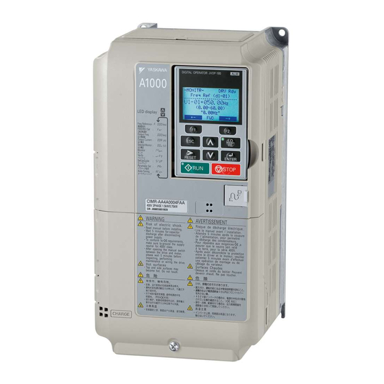
YASKAWA A1000 Installation Manual
Motor pg feedback line driver interface
Hide thumbs
Also See for A1000:
- Technical manual (628 pages) ,
- Quick start manual (358 pages) ,
- Installation manual (70 pages)
Advertisement
Quick Links
YASKAWA AC Drive 1000-Series Option
Motor PG Feedback
Line Driver Interface
Installation Manual
Type: PG-X3
To properly use the product, read this manual thoroughly and retain
for easy reference, inspection, and maintenance. Ensure the end user
receives this manual.
1000
安川インバータ
ラインドライバタイプ
インタフェース
取扱説明書
PG-X3
形 式
製品を安全にお使い頂くために,本書を必ずお読みください。
また,本書をお手元に保管していただくとともに,最終的に本製品をご使用になる
ユーザー様のお手元に確実に届けられるよう,お取り計らい願います。
MANUAL NO. TOBP C730600 37B
シリーズオプション
PG
Advertisement

Related Manuals for YASKAWA A1000


Summary of Contents for YASKAWA A1000
- Page 1 YASKAWA AC Drive 1000-Series Option Motor PG Feedback Line Driver Interface Installation Manual Type: PG-X3 To properly use the product, read this manual thoroughly and retain for easy reference, inspection, and maintenance. Ensure the end user receives this manual. 1000 安川インバータ ...
-
Page 2: Table Of Contents
Yaskawa. No patent liability is assumed with respect to the use of the information contained herein. Moreover, because Yaskawa is constantly striving to improve its high-quality products, the information contained in this manual is subject to change without notice. -
Page 3: Preface And Safety
The selection and application of Yaskawa products remain the responsibility of the equipment manufacturer or end user. Yaskawa accepts no responsibility for the way its products are incorporated into the final system design. Under no circumstances should any Yaskawa product be incorporated into any product or design as the exclusive or sole safety control. - Page 4 Indicates supplemental information that is not related to safety messages Drive: Yaskawa AC Drive 1000-Series Option: Yaskawa AC Drive 1000-Series Option Motor PG Feedback Line Driver Interface: Type PG-X3 Pulse Generator or Encoder Mounted on the Motor ◆ Registered Trademarks Trademarks are the property of their respective owners.
- Page 5 • When ordering new copies of the manual, contact a Yaskawa representative or the nearest Yaskawa sales office and provide the manual number shown on the front cover.
-
Page 6: Product Overview
◆ Applicable Models The option can be used with the drive models in Table Table 1 Applicable Models Drive Series Drive Model Number A1000 All models L1000A All models YASKAWA ELECTRIC TOBP C730600 37B 1000-Series Option PG-X3 Installation Manual... -
Page 7: Receiving
• A pair of diagonal cutting pliers. • A small file or medium-grit sandpaper. Note: Tools required to prepare option cables for wiring are not listed in this manual. YASKAWA ELECTRIC TOBP C730600 37B 1000-Series Option PG-X3 Installation Manual... -
Page 8: Option Components
Terminal Blocks TB1 and TB2 IP IG a− b− z+ z− A− B− Z+ Z− SD FE Refer to Table 5 on page for details on TB1 and TB2 terminal functions and signal levels. YASKAWA ELECTRIC TOBP C730600 37B 1000-Series Option PG-X3 Installation Manual... -
Page 9: Installation Procedure
Do not touch circuit boards while the power to the drive is on. Failure to comply could result in death or serious injury. YASKAWA ELECTRIC TOBP C730600 37B 1000-Series Option PG-X3 Installation Manual... - Page 10 Failure to comply may prevent proper operation and possibly damage equipment. Check wiring to ensure that all connections are correct after installing the option and connecting any other devices. Failure to comply may result in damage to the option. YASKAWA ELECTRIC TOBP C730600 37B 1000-Series Option PG-X3 Installation Manual...
- Page 11 D – Front cover J – Connector CN5-A E – Digital operator K – Connector CN5-B F – Terminal cover L – Connector CN5-C Figure 2 Drive Components with Option YASKAWA ELECTRIC TOBP C730600 37B 1000-Series Option PG-X3 Installation Manual...
- Page 12 After shutting off the power, wait at least the amount of time specified on the drive before touching any components. Figure 3 Figure 3 Remove the Front Covers and Digital Operator YASKAWA ELECTRIC TOBP C730600 37B 1000-Series Option PG-X3 Installation Manual...
- Page 13 2. There are two screw holes on the drive for use as ground terminals. When connecting three options, two ground wires will need to share the same drive ground terminal. YASKAWA ELECTRIC TOBP C730600 37B 1000-Series Option PG-X3 Installation Manual...
- Page 14 Figure 5 (B) for drives that do not require routing through the front cover. For more information, refer to the Peripheral Devices & Options section of Yaskawa AC Drive Technical Manual in your application. Figure 5 A – Route wires through the openings B –...
- Page 15 Two Channel (AB Quadrature) F1-21 = 1 F1-37 = 1 No setting required No setting required Two Channel with Marker (ABZ) F1-21 = 1 F1-37 = 1 No setting required No setting required YASKAWA ELECTRIC TOBP C730600 37B 1000-Series Option PG-X3 Installation Manual...
- Page 16 <1> Ground the shield on the PG side and the drive side. If noise problems arise in the PG signal, remove the shield ground from one end of the signal line or remove the shield ground connection on both ends. YASKAWA ELECTRIC TOBP C730600 37B 1000-Series Option PG-X3 Installation Manual...
- Page 17 Note: Take proper precautions when wiring the option so that the front covers will easily fit back onto the drive. Make sure cables are not pinched between the front covers and the drive when replacing the covers. YASKAWA ELECTRIC TOBP C730600 37B 1000-Series Option PG-X3 Installation Manual...
- Page 18 Please note that when the drive is initialized using A1-03 =1110, 2220, 3330, the value for F1-05/F1-32 will reset to factory default and the parameter will need to be adjusted again to switch the direction. YASKAWA ELECTRIC TOBP C730600 37B 1000-Series Option PG-X3 Installation Manual...
- Page 19 (24 to 16) Crimp Terminals ■ Yaskawa recommends using CRIMPFOX 6 by Phoenix Contact or equivalent to crimp the terminal ends. Note: Properly trim wire ends so loose wire ends do not extend from the crimp terminals. Table 4 Crimp Terminal Sizes...
- Page 20 Z pulse inverse monitor signal <1> A separate power supply is needed if the PG requires more than 200 mA to operate. Select a UL-listed class 2 power supply. YASKAWA ELECTRIC TOBP C730600 37B 1000-Series Option PG-X3 Installation Manual...
-
Page 21: Related Parameters
3: Continue running (383) CLV/PM Range: 0 to 3 Selection Note: Due to potential damage to the motor and AOLV/PM machinery, only use the “Continue running” setting under special circumstances. YASKAWA ELECTRIC TOBP C730600 37B 1000-Series Option PG-X3 Installation Manual... - Page 22 V/f w/ PG PG 1 Hardware 0: Disabled. No fault if the connection is lost. Default: 1 (3B4) Disconnect 1: Enabled. Fault if connection is lost. Range: 0, 1 CLV/PM <3> YASKAWA ELECTRIC TOBP C730600 37B 1000-Series Option PG-X3 Installation Manual...
- Page 23 <5> Enabled only when using the V/f with PG control mode. <6> Depending on the drive series, a second PG (PG 2) may not be possible. Refer to the Yaskawa AC Drive Technical Manual for the drive in your application <7>...
-
Page 24: Troubleshooting
Interface Circuit ■ Figure 11 PG X3 A+,B+,Z+ A,B,Z 600 Ω A ,B ,Z A,B,Z 26LS31 level 26LS32 level a+,b+,z+ a ,b ,z Monitor Signal 26LS31 level Figure 11 Interface Circuit YASKAWA ELECTRIC TOBP C730600 37B 1000-Series Option PG-X3 Installation Manual... - Page 25 The Z channel pulse is out of phase by more than 5 degrees for the number of times specified in parameter F1-17. Cause Possible Solution Separate the PG cable wiring from the source of the noise (e.g., drive output PG cable noise interference. wiring). YASKAWA ELECTRIC TOBP C730600 37B 1000-Series Option PG-X3 Installation Manual...
- Page 26 • Make sure the motor is rotating in the proper direction. is cable affecting the A or B • Investigate problems on the load-side that may be causing the motor to rotate in pulse. the opposite direction. YASKAWA ELECTRIC TOBP C730600 37B 1000-Series Option PG-X3 Installation Manual...
- Page 27 • Increase the settings for C5-01 (Speed Control Proportional Gain 1) and reduce Overshoot is occurring. C5-02 (Speed Control Integral Time 1). • Enable Feed Forward Control and perform Inertia Auto-Tuning in CLV. YASKAWA ELECTRIC TOBP C730600 37B 1000-Series Option PG-X3 Installation Manual...
- Page 28 Brake is holding the PG. Ensure the brake releases properly. Digital Operator Display Fault Name PG Hardware Fault PGoH PG cable is disconnected. Cause Possible Solution PG cable is disconnected. Reconnect the cable. YASKAWA ELECTRIC TOBP C730600 37B 1000-Series Option PG-X3 Installation Manual...
-
Page 29: Specifications
-20 °C to +60 °C (-4 °F to 140 °F) allowed for short-term transport of the product Storage Temperature Area of Use Indoor (free of corrosive gas, airborne particles, etc.) Altitude 1000 m (3280 ft.) or lower YASKAWA ELECTRIC TOBP C730600 37B 1000-Series Option PG-X3 Installation Manual... - Page 30 November 2009 Entire Document Edited for procedural clarity and readability. Addition: Connection Diagram April 2009 Chapter 4 Instruction to counteract noise by grounding shielded lines. − − July 2008 First edition YASKAWA ELECTRIC TOBP C730600 37B 1000-Series Option PG-X3 Installation Manual...
- Page 31 Phone: 81-3-5402-4502 Fax: 81-3-5402-4580 http://www.yaskawa.co.jp YASKAWA AMERICA, INC. 2121 Norman Drive South, Waukegan, IL 60085, U.S.A. Phone: 1-800-YASKAWA (927-5292) or 1-847-887-7000 Fax: 1-847-887-7310 http://www.yaskawa.com YASKAWA ELÉTRICO DO BRASIL LTDA. Avenida Piraporinha 777, Diadema, São Paulo, 09950-000, Brasil Phone: 55-11-3585-1100 Fax: 55-11-3585-1187 http://www.yaskawa.com.br...