Sign In
Upload
Manuals
Brands
YASKAWA Manuals
Controller
A1000 Series
YASKAWA A1000 Series Manuals
Manuals and User Guides for YASKAWA A1000 Series. We have
17
YASKAWA A1000 Series manuals available for free PDF download: Technical Manual, Quick Start Manual, Installation Manual, Product Replacement Manual, Manual, Setup
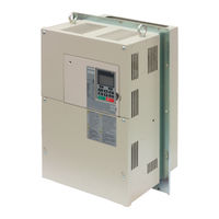
YASKAWA A1000 Series Technical Manual (544 pages)
High Performance Vector Control Drive Models: 200 V Class: 0.4 to 110 kW 400 V Class: 0.4 to 355 kW
Brand:
YASKAWA
| Category:
Controller
| Size: 56.82 MB
Table of Contents
Table of Contents
5
Quick Reference
3
Table of Contents
5
I.1 Preface
16
Applicable Documentation
16
Symbols
16
Terms and Abbreviations
16
I.2 General Safety
17
Supplemental Safety Information
17
Safety Messages
18
Application Notes
19
Notes on Motor Operation
21
Applications with Specialized Motors
22
Drive Label Warnings
24
Warranty Information
24
Receiving
25
Section Safety
26
General Description
27
A1000 Model Selection
27
Control Mode Selection
28
Model Number and Nameplate Check
29
Nameplate
29
Drive Models and Enclosure Types
31
Component Names
32
IP20/NEMA Type 1 Enclosure
32
IP00 Enclosure
32
Front Views
35
Mechanical Installation
37
Section Safety
38
Installation Environment
40
2 Mechanical Installation
40
Installation Orientation and Spacing
40
Digital Operator Remote Usage
42
Exterior and Mounting Dimensions
46
Electrical Installation
51
Section Safety
52
Standard Connection Diagram
54
Main Circuit Connection Diagram
56
Three-Phase 200 V Class (CIMR-A 2A0169 to
56
Three-Phase 400 V Class (CIMR-A 4A0088 to 0675)
56
Terminal Block Configuration
57
Terminal Cover
59
CIMR-A 2A0004 to 0081, 4A0002 to 0044 (IP20/NEMA Type 1 Enclosure)
59
CIMR-A 2A0110 to 0415, 4A0058 to 0675 (IP00 Enclosure)
60
Digital Operator and
61
Removing/Reattaching the Digital Operator
61
Removing/Reattaching the Front Cover
61
Top Protective Cover
64
Reattaching the Top Protective Cover
64
Removing the Top Protective Cover
64
Main Circuit Wiring
65
Main Circuit Terminal Functions
65
Protecting Main Circuit Terminals
65
Wire Gauges and Tightening Torque
66
Main Circuit Terminal and Motor Wiring
70
Control Circuit Wiring
72
Control Circuit Connection Diagram
72
Control Circuit Terminal Block Functions
72
Terminal Configuration
73
Wiring the Control Circuit Terminal
74
Switches and Jumpers on the Terminal Board
76
Control I/O Connections
77
Sinking/Sourcing Mode Selection for Safe Disable Inputs
77
Sinking/Sourcing Mode Switch for Digital Inputs
77
Using the Pulse Train Output
78
Terminal A2 Input Signal Selection
79
Terminal A3 Analog/Ptc Input Selection
79
Terminal AM/FM Signal Selection
79
Memobus/Modbus Termination
80
Connect to a Pc
81
External Interlock
82
Drive Ready
82
Wiring Checklist
83
Start-Up Programming & Operation
85
Section Safety
86
Keys and Displays
87
Using the Digital Operator
87
LCD Display
88
ALARM (ALM) LED Displays
89
LO/RE LED and RUN LED Indications
89
Menu Structure for Digital Operator
90
The Drive and Programming Modes
91
Navigating the Drive and Programming Modes
91
Changing Parameter Settings or Values
92
Verifying Parameter Changes: Verify Menu
94
Simplified Setup Using the Setup Group
95
Switching between LOCAL and REMOTE
96
Start-Up Flowcharts
98
Flowchart A: Basic Start-Up and Motor Tuning
98
Subchart A-1: Simple Motor Setup Using V/F Control
99
Subchart A-2: High Performance Operation Using OLV or CLV
100
Subchart A-3: Operation with Permanent Magnet Motors
101
Powering up the Drive
102
Powering up the Drive and Operation Status Display
102
Application Selection
103
Setting 1: Water Supply Pump Application
103
Setting 2: Conveyor Application
103
Setting 3: Exhaust Fan Application
104
Setting 4: HVAC Fan Application
104
Setting 5: Compressor Application
105
Setting 6: Hoist Application
105
Notes on Controlling the Brake When Using the Hoist Application Preset
106
Setting 7: Traveling Application
108
Auto-Tuning
109
Types of Auto-Tuning
109
Before Auto-Tuning the Drive
111
Auto-Tuning Interruption and Fault Codes
112
Auto-Tuning Operation Example
112
Parameter Settings During Induction Motor Auto-Tuning: T1
114
Parameter Settings During PM Motor Auto-Tuning: T2
116
Parameter Settings During Inertia and Speed Control Loop Auto-Tuning: T3
119
No-Load Operation Test Run
121
Test Run with Load Connected
123
Test Run with the Load Connected
123
Verifying Parameter Settings and Backing up Changes
124
Backing up Parameter Values: O2-03
124
Parameter Access Level: A1-01
124
Password Settings: A1-04, A1-05
124
Copy Function
125
Test Run Checklist
126
Parameter Details
129
A1: Initialization
130
A: Initialization
130
A2: User Parameters
135
B1: Operation Mode Selection
136
B: Application
136
B2: DC Injection Braking and Short Circuit Braking
144
B3: Speed Search
146
B4: Delay Timers
151
B5: PID Control
152
B6: Dwell Function
161
B7: Droop Control (CLV, CLV/PM)
162
B8: Energy Saving
163
B9: Zero Servo
164
C1: Acceleration and Deceleration Times
165
C: Tuning
165
C2: S-Curve Characteristics
167
C3: Slip Compensation
167
C4: Torque Compensation
170
C5: Automatic Speed Regulator (ASR)
171
C6: Carrier Frequency
177
D: Reference Settings
180
D1: Frequency Reference
180
D2: Frequency Upper/Lower Limits
182
D3: Jump Frequency
182
D4: Frequency Reference Hold and Up/Down 2 Function
183
D5: Torque Control
188
D6: Field Weakening and Field Forcing
192
D7: Offset Frequency
193
E: Motor Parameters
194
E1: V/F Pattern for Motor 1
194
E2: Motor 1 Parameters
198
E3: V/F Pattern for Motor 2
201
E4: Motor 2 Parameters
202
E5: PM Motor Settings
204
F: Option Settings
206
F1: PG Speed Control Card Settings
206
F2: Analog Input Card Settings
209
F3: Digital Input Card Settings
209
F4: Analog Monitor Card Settings
210
F5: Digital Output Card Settings
211
F6: Communication Option Card
211
Canopen Parameters
213
CC-Link Parameters
213
Devicenet Parameters
213
H: Terminal Functions
214
MECHATROLINK Parameters
213
PROFIBUS-DP Parameters
213
H1: Multi-Function Digital Inputs
214
H2: Multi-Function Digital Outputs
224
H3: Multi-Function Analog Inputs
234
H4: Multi-Function Analog Outputs
239
H5: Memobus/Modbus Serial Communication
241
H6: Pulse Train Input/Output
241
L: Protection Functions
244
L1: Motor Protection
244
L2: Momentary Power Loss Ride-Thru
249
L3: Stall Prevention
255
L4: Speed Detection
262
L5: Fault Restart
263
L6: Torque Detection
264
L7: Torque Limit
267
L8: Drive Protection
269
N: Special Adjustments
275
N1: Hunting Prevention
275
N2: Speed Feedback Detection Control (AFR) Tuning
276
N3: High Slip Braking (HSB) and Overexcitation Braking
276
N5: Feed Forward Control
279
N6: Online Tuning
280
N8: PM Motor Control Tuning
281
O: Operator Related Settings
284
O1: Digital Operator Display Selection
284
O2: Digital Operator Keypad Functions
285
O3: Copy Function
287
O4: Maintenance Monitor Settings
288
Q: Driveworksez Parameters
289
R: Driveworksez Connection Parameters
289
T: Motor Tuning
290
U: Monitor Parameters
291
U1: Operation Status Monitors
291
U2: Fault Trace
291
U3: Fault History
291
U4: Maintenance Monitors
291
U5: PID Monitors
291
U6: Operation Status Monitors
291
U8: Driveworksez Monitors
292
Troubleshooting
293
Section Safety
294
Fine-Tuning Open Loop Vector Control
296
Fine-Tuning V/F Control and V/F Control with PG
296
Motor Performance Fine-Tuning
296
Fine-Tuning Closed Loop Vector Control
297
Fine-Tuning Open Loop Vector Control for PM Motors
297
Fine-Tuning Advanced Open Loop Vector Control for PM Motors
298
Fine-Tuning Closed Loop Vector Control for PM Motors
298
Parameters to Minimize Motor Hunting and Oscillation
299
Drive Alarms, Faults, and Errors
300
Types of Alarms, Faults, and Errors
300
Alarm and Error Displays
301
Fault Detection
306
Fault Displays, Causes, and Possible Solutions
306
Alarm Detection
319
Alarm Codes, Causes, and Possible Solutions
319
Operator Programming Errors
325
Ope Codes, Causes, and Possible Solutions
325
Auto-Tuning Fault Detection
328
Auto-Tuning Codes, Causes, and Possible Solutions
328
Copy Function Related Displays
332
Tasks, Errors, and Troubleshooting
332
Diagnosing and Resetting Faults
334
Fault Occurs Simultaneously with Power Loss
334
If the Drive Still Has Power after a Fault Occurs
334
Viewing Fault Trace Data after Fault
334
Fault Reset Methods
335
Troubleshooting Without Fault Display
336
Common Problems
336
Cannot Change Parameter Settings
336
Motor Does Not Rotate Properly after Pressing RUN Button or after
336
Entering External Run Command
337
Motor Is too Hot
338
Drive Does Not Allow Selection the Desired Auto-Tuning Mode
338
Ope02 Error Occurs When Lowering the Motor Rated Current Setting
338
Motor Stalls During Acceleration or Acceleration Time Is too Long
338
Reference Command
339
Excessive Motor Oscillation and Erratic Rotation
339
Deceleration Takes Longer than Expected with Dynamic Braking Enabled
339
Load Falls When Brake Is Applied (Hoist-Type Applications)
339
Noise from Drive or Output Lines When the Drive Is Powered on
340
Earth Leakage Circuit Breaker (ELCB) Trips During Run
340
Connected Machinery Vibrates When Motor Rotates
340
PID Output Fault
340
Insufficient Starting Torque
340
Output Frequency Is Not as High as Frequency Reference
341
Buzzing Sound from Motor at 2 Khz
341
Unstable Motor Speed When Using PM
341
Motor Does Not Restart after Power Loss
341
Advertisement
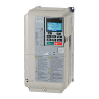
YASKAWA A1000 Series Technical Manual (628 pages)
High Performance Vector Control Drive Type: CIMR-A series Models: 200 V Class: 0.55 to 110 kW, 400 V Class: 0.55 to 630 kW
Brand:
YASKAWA
| Category:
Controller
| Size: 55.44 MB
Table of Contents
Table of Contents
5
YASKAWA ELECTRIC SIEP C710616 27G YASKAWA AC Drive A1000 Technical Manual
13
I.1 Preface
15
Applicable Documentation
16
I.2 General Safety
19
Application Notes
21
Notes on Motor Operation
23
Applications with Specialized Motors
24
Drive Label Warnings
25
Warranty Information
26
Receiving
27
Section Safety
28
General Description
29
General Description
31
Model Number and Nameplate Check
32
Drive Models and Enclosure Types
33
Drive Models and Enclosure Types
34
Component Names
35
Component Names
37
IP00 Enclosure
38
Front Views
42
2 Mechanical Installation
43
Section Safety
44
Mechanical Installation
48
Digital Operator Remote Usage
50
Exterior and Mounting Dimensions
52
Electrical Installation
57
Section Safety
58
Standard Connection Diagram
60
Standard Connection Diagram
62
Main Circuit Configurations
63
Main Circuit Configurations
65
Terminal Block Configuration
66
Terminal Block Configuration
67
Terminal Cover
68
Terminal Cover
69
Digital Operator and
70
Digital Operator and Front Cover
71
Top Protective Cover
74
Main Circuit Wiring
75
Protecting Main Circuit Terminals
76
Main Circuit Terminal and Motor Wiring
81
Control Circuit Wiring
83
Terminal Configuration
84
Wiring the Control Circuit Terminal
85
Switches and Jumpers on the Terminal Board
87
Control I/O Connections
88
Using the Pulse Train Output
89
Terminal A2 Input Signal Selection
90
Memobus/Modbus Termination
91
Connect to a Pc
92
External Interlock
93
Wiring Checklist
94
Start-Up Programming & Operation
97
Section Safety
98
Using the Digital Operator
99
LCD Display
100
ALARM (ALM) LED Displays
101
Menu Structure for Digital Operator
102
The Drive and Programming Modes
103
Changing Parameter Settings or Values
105
Verifying Parameter Changes: Verify Menu
106
Simplified Setup Using the Setup Group
107
Switching between LOCAL and REMOTE
108
Start-Up Flowcharts
109
Subchart A-1: Simple Motor Setup Using V/F Control
110
Subchart A-2: High Performance Operation Using OLV or CLV
111
Subchart A-3: Operation with Permanent Magnet Motors
112
Powering up the Drive
113
Application Selection
114
Setting 2: Conveyor Application
115
Setting 5: Compressor Application
116
Notes on Controlling the Brake When Using the Hoist Application Preset
117
Setting 7: Traveling Application
119
Auto-Tuning
120
Before Auto-Tuning the Drive
123
Auto-Tuning Interruption and Fault Codes
125
Parameter Settings During Induction Motor Auto-Tuning: T1
127
Parameter Settings During PM Motor Auto-Tuning: T2
130
Parameter Settings During Inertia and Speed Control Loop Auto-Tuning: T3
132
No-Load Operation Test Run
134
Test Run with Load Connected
136
Verifying Parameter Settings and Backing up Changes
137
Copy Function
138
Test Run Checklist
139
Parameter Details
141
A: Initialization
142
A2: User Parameters
147
B: Application
148
B2: DC Injection Braking and Short Circuit Braking
158
B3: Speed Search
160
B4: Delay Timers
166
B5: PID Control
167
B6: Dwell Function
178
B8: Energy Saving
179
B9: Zero Servo
181
C: Tuning
183
C2: S-Curve Characteristics
185
C4: Torque Compensation
188
C5: Automatic Speed Regulator (ASR)
190
C6: Carrier Frequency
195
D: Reference Settings
198
D2: Frequency Upper/Lower Limits
200
D4: Frequency Reference Hold and Up/Down 2 Function
201
D5: Torque Control
206
D6: Field Weakening and Field Forcing
210
D7: Offset Frequency
211
E: Motor Parameters
212
E2: Motor 1 Parameters
216
E3: V/F Pattern for Motor 2
219
E4: Motor 2 Parameters
220
E5: PM Motor Settings
222
F: Option Settings
225
F2: Analog Input Card Settings
228
F3: Digital Input Card Settings
229
F4: Analog Monitor Card Settings
230
F5: Digital Output Card Settings
231
H: Terminal Functions
235
H2: Multi-Function Digital Outputs
246
H3: Multi-Function Analog Inputs
257
H4: Multi-Function Analog Outputs
262
H5: Memobus/Modbus Serial Communication
264
L: Protection Functions
267
L2: Momentary Power Loss Ride-Thru
274
L3: Stall Prevention
281
L4: Speed Detection
288
L5: Fault Restart
290
L6: Torque Detection
291
L7: Torque Limit
294
L8: Drive Protection
295
L9: Drive Protection 2
301
N: Special Adjustments
302
N2: Speed Feedback Detection Control (AFR) Tuning
303
N5: Feed Forward Control
306
N6: Online Tuning
307
N8: PM Motor Control Tuning
308
O: Operator Related Settings
314
O2: Digital Operator Keypad Functions
315
O3: Copy Function
318
Q: Driveworksez Parameters
320
U: Monitor Parameters
321
U6: Control Monitors
322
Troubleshooting
323
Section Safety
324
Motor Performance Fine-Tuning
326
Fine-Tuning Closed Loop Vector Control
327
Fine-Tuning Advanced Open Loop Vector Control for PM Motors
328
Parameters to Minimize Motor Hunting and Oscillation
329
Drive Alarms, Faults, and Errors
330
Alarm and Error Displays
331
Fault Detection
336
Alarm Detection
350
Operator Programming Errors
357
Causes and Possible Solutions for a Blank and Unresponsive Digital Operator
359
Auto-Tuning Fault Detection
360
Copy Function Related Displays
364
Diagnosing and Resetting Faults
366
Fault Reset Methods
367
Troubleshooting Without Fault Display
368
External Run Command
369
Motor Is too Hot
370
Motor Stalls During Acceleration or Acceleration Time Is too Long
371
Deceleration Takes Longer than Expected with Dynamic Braking Enabled
372
PID Output Fault
373
Unstable Motor Speed When Using PM
374
YASKAWA A1000 Series Quick Start Manual (358 pages)
High Performance Vector Control Drive
Brand:
YASKAWA
| Category:
Controller
| Size: 14.79 MB
Table of Contents
Quick Reference
3
Table of Contents
5
Preface & General Safety
11
Preface
12
Applicable Documentation
12
I.1 Preface
12
General Safety
13
Supplemental Safety Information
13
I.2 General Safety
13
Safety Messages
14
General Application Precautions
15
Motor Application Precautions
18
Drive Label Warning Example
20
Warranty Information
20
1 Receiving
21
Model Number and Nameplate Check
22
Nameplate
22
2 Mechanical Installation
27
Mechanical Installation
28
Installation Environment
28
Installation Orientation and Spacing
28
Instructions on Installation Using the Eye Bolts
30
Flange Type Enclosure (NEMA 12 Backside) Dimensions & Heat Loss
41
Flange Type Models 2A0004 to 2A0012, 4A0002 to 4A0005, and 5A0003 and 5A0004
41
Flange Type Models 2A0018 and 2A0021, 4A0007 to 4A0011, and 5A0006 and 5A0009
44
Flange Type Models 2A0030 and 2A0040, 4A0018 and 4A0023, and 5A0011
47
Flange Type Model 4A0031
50
Flange Type Models 2A0056, 4A0038, and 5A0017 and 5A0022
52
Flange Type Models 2A0069 and 2A0081, 4A0044, and 5A0027 and 5A0032
55
Flange Type Models 2A0110 and 4A0058
58
Flange Type Models 2A0138, 4A0072, and 5A0041 and 5A0052
60
Flange Type Models 4A0088 and 4A0103
62
Flange Type Models 2A0169 and 2A0211, 4A0139 and 4A0165, and 5A0062 to 5A0099
64
Flange Type Models 2A0250 and 2A0312, 4A0208, and 5A0125 and 5A0145
67
Flange Type Models 2A0360 and 2A0415, 4A0250 to 4A0362, and 5A0192 and 5A0242
69
Flange Type Model 4A0414
72
Flange Type Models 4A0515 and 4A0675
74
Flange Type Models 4A0930 and 4A1200
76
3 Electrical Installation
79
Standard Connection Diagram
80
Main Circuit Connection Diagram
83
Three-Phase 200 V Class Models 2A0004 to 2A0081 Three-Phase 400 V Class Models 4A0002 to 4A0044 Three-Phase 600 V Class Models 5A0003 to 5A0032
83
Three-Phase 200 V Class Models 2A0110, 2A0138 Three-Phase 400 V Class Models 4A0058, 4A0072 Three-Phase 600 V Class Models 5A0041, 5A0052
83
Three-Phase 200 V Class Models 2A0169 to 2A0211 Three-Phase 400 V Class Models 4A0088 to 4A0139 Three-Phase 600 V Class Models 5A0062 to 5A0099
84
Three-Phase 200 V Class Models 2A0250 to 2A0415 Three-Phase 400 V Class Models 4A0165 to 4A0675 Three-Phase 600 V Class Models 5A0125 to 5A0242
84
Three-Phase 400 V Class Models 4A0930, 4A1200
85
12-Pulse Rectification
85
Terminal Cover
87
Models 2A0004 to 2A0081, 4A0002 to 4A0044, 5A0003 to 5A0032 (IP20/NEMA 1, UL Type 1 Enclosure)
87
Models 2A0110 to 2A0250, 4A0208 to 4A1200, and 5A0125 to 5A0242 (Ip00/Open Type Enclosure)
88
Digital Operator and
89
Removing/Reattaching the Digital Operator
89
Removing/Reattaching the
89
Top Protective Cover
92
Removing the Top Protective Cover
92
Reattaching the Top Protective Cover
92
Main Circuit Wiring
93
Main Circuit Terminal Functions
93
Protecting Main Circuit Terminals
94
Main Circuit Wire Gauges and Tightening Torques
94
Main Circuit Terminal and Motor Wiring
103
Control Circuit Wiring
105
Control Circuit Terminal Block Functions
105
Terminal Configuration
107
Wiring the Control Circuit Terminal
108
Control I/O Connections
110
Sinking/Sourcing Mode for Digital Inputs
110
Sinking/Sourcing Mode Selection for Safe Disable Inputs
111
Using the Pulse Train Output
112
Terminal A2 Input Signal Selection
113
Terminal A3 Analog/Ptc Input Selection
113
Terminal AM/FM Signal Selection
113
Terminal DM+ and DM- Output Signal Selection
114
Connect to a PC
115
Wiring Checklist
116
4 Start-Up Programming & Operation
119
Using the Digital Operator
120
Digital Operator Keys and Displays
120
LCD Display
121
ALARM (ALM) LED Displays
122
LO/RE LED and RUN LED Indications
122
Menu Structure for Digital Operator
123
The Drive and Programming Modes
124
Changing Parameter Settings or Values
124
Switching between LOCAL and REMOTE
126
Start-Up Flowcharts
127
Flowchart A: Basic Start-Up and Motor Tuning
128
Subchart A-1: Simple Motor Setup Using V/F Control
129
Subchart A-2: High Performance Operation Using OLV or CLV
130
Subchart A-3: Operation with Permanent Magnet Motors
131
Powering up the Drive
133
Powering up the Drive and Operation Status Display
133
Application Selection
134
Basic Drive Setup Adjustments
135
Auto-Tuning
164
Types of Auto-Tuning
164
Auto-Tuning Interruption and Fault Codes
167
Auto-Tuning Operation Example
169
No-Load Operation Test Run
171
Test Run with Load Connected
173
Test Run with the Load Connected
173
Test Run Checklist
174
5 Troubleshooting
177
Drive Alarms, Faults, and Errors
178
Types of Alarms, Faults, and Errors
178
Fault Detection
179
Fault Displays, Causes, and Possible Solutions
179
Alarm Detection
196
Alarm Codes, Causes, and Possible Solutions
196
Operator Programming Errors
203
Operator Programming Error Codes, Causes, and Possible Solutions
203
Causes and Possible Solutions for a Blank and Unresponsive Digital Operator
204
Auto-Tuning Fault Detection
205
Auto-Tuning Codes, Causes, and Possible Solutions
205
Copy Function Related Displays
211
Tasks, Errors, and Troubleshooting
211
Fault Reset Methods
211
6 Periodic Inspection & Maintenance
213
Inspection
214
Recommended Daily Inspection
214
Recommended Periodic Inspection
215
Storage Guidelines
216
Periodic Maintenance
217
Replacement Parts
217
Drive Replacement
219
Replacing the Drive
219
7 Peripheral Devices & Options
221
Option Card Installation
222
Prior to Installing the Option
222
PG Option Installation Example
223
Specifications
233
Heavy Duty and Normal Duty Ratings
234
Power Ratings
235
Three-Phase 200 V Class Drive Models 2A0004 to 2A0030
235
Three-Phase 200 V Class Drive Models 2A0040 to 2A0211
236
Three-Phase 200 V Class Drive Models 2A0250 to 2A0415
237
Three-Phase 400 V Class Drive Models 4A0002 to 4A0031
238
Three-Phase 400 V Class Drive Models 4A0038 to 4A0165
239
Three-Phase 400 V Class Drive Models 4A0208 to 4A1200
240
Three-Phase 600 V Class Drive Models 5A0003 to 5A0032
241
Three-Phase 600 V Class Drive Models 5A0041 to 5A0099
242
Three-Phase 600 V Class Drive Models 5A0125 to 5A0242
243
Drive Specifications
244
Drive Watt Loss Data
246
Advertisement
YASKAWA A1000 Series Technical Manual (257 pages)
Brand:
YASKAWA
| Category:
Controller
| Size: 14.89 MB
Table of Contents
Quick Reference
3
Table of Contents
5
Preface & General Safety
11
Preface
12
Applicable Documentation
12
I.1 Preface
12
General Safety
13
Supplemental Safety Information
13
I.2 General Safety
13
Safety Messages
14
General Application Precautions
15
Motor Application Precautions
18
Drive Label Warning Example
20
Warranty Information
20
1 Receiving
21
Model Number and Nameplate Check
22
Nameplate
22
2 Mechanical Installation
27
Mechanical Installation
28
Installation Environment
28
Installation Orientation and Spacing
28
3 Electrical Installation
37
Standard Connection Diagram
38
Main Circuit Connection Diagram
41
Three-Phase 200 V Class (CIMR-Ao2A0004 to 2A0081) Three-Phase 400 V Class (CIMR-Ao4A0002 to 4A0044) Three-Phase 600 V Class (CIMR-Ao5A0003 to 5A0032)
41
Three-Phase 200 V Class (CIMR-Ao2A0110, 2A0138) Three-Phase 400 V Class (CIMR-Ao4A0058, 4A0072) Three-Phase 600 V Class (CIMR-Ao5A0041, 5A0052)
41
Three-Phase 200 V Class (CIMR-Ao2A0169 to 2A0415) Three-Phase 400 V Class (CIMR-Ao4A0088 to 4A0675) Three-Phase 600 V Class (CIMR-Ao5A0062 to 5A0099)
41
Three-Phase 400 V Class (CIMR-Ao4A0930, 4A1200)
42
12-Phase Rectification
42
Terminal Cover
44
CIMR-Ao2A0004 to 2A0081, 4A0002 to 4A0044, 5A0003 to 5A0032
44
(IP20/NEMA Type 1 Enclosure)
44
CIMR-Ao2A0110 to 2A0415, 4A0058 to 4A1200 (IP00 Enclosure)
45
Digital Operator and
46
Removing/Reattaching the Digital Operator
46
Removing/Reattaching the
46
Top Protective Cover
49
Removing the Top Protective Cover
49
Reattaching the Top Protective Cover
49
Main Circuit Wiring
50
Main Circuit Terminal Functions
50
Protecting Main Circuit Terminals
51
Wire Gauges and Tightening Torque
52
Main Circuit Terminal and Motor Wiring
59
Control Circuit Wiring
61
Control Circuit Terminal Block Functions
61
Terminal Configuration
63
Wiring the Control Circuit Terminal
64
Control I/O Connections
66
Sinking/Sourcing Mode Switch for Digital Inputs
66
Sinking/Sourcing Mode Selection for Safe Disable Inputs
67
Using the Pulse Train Output
67
Terminal A2 Input Signal Selection
68
Terminal A3 Analog/Ptc Input Selection
68
Terminal AM/FM Signal Selection
69
Connect to a PC
70
Wiring Checklist
71
4 Start-Up Programming & Operation
73
Using the Digital Operator
74
Keys and Displays
74
LCD Display
75
ALARM (ALM) LED Displays
76
LO/RE LED and RUN LED Indications
76
Menu Structure for Digital Operator
77
The Drive and Programming Modes
78
Changing Parameter Settings or Values
78
Switching between LOCAL and REMOTE
79
Start-Up Flowcharts
81
Flowchart A: Basic Start-Up and Motor Tuning
82
Subchart A-1: Simple Motor Setup Using V/F Control
83
Subchart A-2: High Performance Operation Using OLV or CLV
84
Subchart A-3: Operation with Permanent Magnet Motors
85
Powering up the Drive
86
Powering up the Drive and Operation Status Display
86
Application Selection
87
Basic Drive Setup Adjustments
88
Auto-Tuning
116
Types of Auto-Tuning
116
Auto-Tuning Interruption and Fault Codes
119
Auto-Tuning Operation Example
119
No-Load Operation Test Run
122
Test Run with Load Connected
124
Test Run with the Load Connected
124
Test Run Checklist
125
5 Troubleshooting
127
Drive Alarms, Faults, and Errors
128
Types of Alarms, Faults, and Errors
128
Fault Detection
129
Fault Displays, Causes, and Possible Solutions
129
Alarm Detection
140
Alarm Codes, Causes, and Possible Solutions
140
Operator Programming Errors
143
Operator Programming Error Codes, Causes, and Possible Solutions
143
Auto-Tuning Fault Detection
144
Auto-Tuning Codes, Causes, and Possible Solutions
144
Copy Function Related Displays
148
Tasks, Errors, and Troubleshooting
148
Fault Reset Methods
148
6 Periodic Inspection & Maintenance
149
Inspection
150
Recommended Daily Inspection
150
Recommended Periodic Inspection
151
Periodic Maintenance
153
Replacement Parts
153
Drive Replacement
155
Replacing the Drive
155
7 Peripheral Devices & Options
157
Option Card Installation
158
Installing Option Cards
158
Installation Procedure
158
Specifications
161
Heavy Duty and Normal Duty Ratings
162
Power Ratings
163
Three-Phase 200 V Class Drive Models CIMR-Ao2A0004 to 2A0030
163
Three-Phase 200 V Class Drive Models CIMR-Ao2A0040 to 2A0211
164
Three-Phase 200 V Class Drive Models CIMR-Ao2A0250 to 2A0415
165
Three-Phase 400 V Class Drive Models CIMR-Ao4A0002 to 4A0031
166
Three-Phase 400 V Class Drive Models CIMR-Ao4A0038 to 4A0165
167
Three-Phase 400 V Class Drive Models CIMR-Ao4A0208 to 4A1200
168
Three-Phase 600 V Class Drive Models CIMR-Ao5A0003 to 5A0032
169
Three-Phase 600 V Class Drive Models CIMR-Ao5A0041 to 5A0099
170
Drive Specifications
171
Drive Watt Loss Data
173
YASKAWA A1000 Series Quick Start Manual (195 pages)
High Performance Vector Control Drive
Brand:
YASKAWA
| Category:
Controller
| Size: 20.58 MB
Table of Contents
Quick Reference
3
Table of Contents
5
Preface & General Safety
7
Preface
7
General Safety
7
1 Receiving
17
Model Number and Nameplate Check
17
2 Mechanical Installation
19
3 Electrical Installation
26
Standard Connection Diagram
26
Main Circuit Connection Diagram
28
Terminal Cover
29
Digital Operator and
31
Top Protective Cover
33
Main Circuit Wiring
34
Control I/O Connections
48
Terminal A2 Analog Input Signal Selection
50
Connect to a PC
51
Wiring Checklist
51
4 Start-Up Programming & Operation
53
Using the Digital Operator
53
The Drive and Programming Modes
56
Start-Up Flowcharts
58
Powering up the Drive
63
Application Selection
63
Basic Drive Setup Adjustments
64
Auto-Tuning
91
No-Load Operation Test Run
95
Test Run with Load Connected
96
Test Run Checklist
97
5 Troubleshooting
99
Drive Alarms, Faults, and Errors
99
Fault Detection
100
Alarm Detection
110
Operator Programming Errors
112
Auto-Tuning Fault Detection
113
Copy Function Related Displays
117
6 Periodic Inspection & Maintenance
118
Inspection
118
Periodic Maintenance
120
Specifications
124
Heavy Duty and Normal Duty Ratings
124
Three-Phase 200 V Class Drives
125
Three-Phase 400 V Class Drives
126
Drive Specifications
128
Drive Watt Loss Data
129
Parameter List
131
A: Initialization Parameters
131
B: Application
132
C: Tuning
137
D: References
141
E: Motor Parameters
144
F: Options
148
H: Multi-Function Terminals
154
L: Protection Function
162
N: Special Adjustment
168
O: Operator Related Settings
170
Q: Driveworksez Parameters
172
R: Driveworksez Connection Parameters
172
T: Motor Tuning
172
U: Monitors
175
YASKAWA A1000 Series Installation Manual (70 pages)
Brand:
YASKAWA
| Category:
DC Drives
| Size: 5.37 MB
Table of Contents
Table of Contents
3
Preface & General Safety
5
Preface
6
Applicable Documentation
6
General Safety
7
General Application Precautions
7
Receiving
9
Model Number and Nameplate Check
10
Nameplate
10
Component Names
12
Flange Type Enclosure (NEMA Type 12 Backside)
12
Mechanical Installation
13
Mechanical Installation
14
Installation Environment
14
Removing the Shipping Package Attachments
15
Dimensions
15
Panel Cut-Out Dimensions
21
Weight
25
Electrical Installation
27
Standard Connection Diagram
28
Main Circuit Connection Diagram
31
6-Phase/12-Pulse Input 400 V Class (CIMR-A 4T0058, 0072)
31
6-Phase/12-Pulse Input 400 V Class (CIMR-A 4T0088 to 0139)
31
6-Phase/12-Pulse Input 400 V Class (CIMR-A 4T0165 to 0675)
32
6-Phase/12-Pulse Rectification
33
Main Circuit Terminal Configuration
34
Main Circuit Wiring
37
Main Circuit Terminal Functions
37
Main Circuit Fuses
37
Wire Gauges and Tightening Torque
38
Wiring Checklist
41
Start-Up Programming & Operation
43
Powering up the Drive
44
Peripheral Devices & Options
45
Drive Options and Peripheral Devices
46
Connecting Peripheral Devices
48
Installing Peripheral Devices
49
Dynamic Braking Options
49
Specifications
51
Power Ratings
52
6-Phase/12 Pulse Input 400 V Class Drive Models CIMR-A 4T0058 to 0208
52
6-Phase/12 Pulse Input 400 V Class Drive Models CIMR-A 4T0208 to 0675
53
Drive Specifications
54
Drive Watt Loss Data
56
Drive Derating Data
57
Temperature Derating
57
Altitude Derating
57
Parameter List
59
L: Protection Function
60
L8: Drive Protection
60
YASKAWA A1000 Series Product Replacement Manual (44 pages)
Brand:
YASKAWA
| Category:
Inverter
| Size: 1.77 MB
Table of Contents
Table of Contents
1
Applicable Models
2
Replacement Checklist
4
Terminal Compatibility Chart
6
Main Circuit Terminals
6
Control Circuit Terminals, Signal Levels
12
Communication Circuit Terminals
15
Terminal Sizes and Wire Gauge
16
Dimensions and Installation Adapters
29
Exterior and Mounting Dimensions
29
UL Type 1 Kit
32
Adapters and Attachments to Match Mounting Dimensions
34
Braking Resistor Installation Attachment
36
Parameter Transition Guide
37
Parameter Setting Transition Instructions
37
Checking Modified Parameters with A1000 Verify Menu
37
Parameter Compatibility Table
38
Carrier Frequency and Rated Current Derating
40
Matching Keypad and Operator
42
Revision History
44
YASKAWA A1000 Series Quick Start Manual (52 pages)
Frequency High Performance Vector Control AC Drive
Brand:
YASKAWA
| Category:
Controller
| Size: 5.92 MB
Table of Contents
Table of Contents
3
Safety Instructions and General Warnings
4
Mechanical Installation
8
Figure
9
Electrical Installation
12
Keypad Operation
19
Start up
21
Parameter Table
26
Troubleshooting
31
Safe Disable Input Function
35
Ul Standards
38
YASKAWA A1000 Series Technical Manual (44 pages)
Brand:
YASKAWA
| Category:
Controller
| Size: 3.96 MB
Table of Contents
Table of Contents
3
Preface and Safety
4
Product Overview
6
Receiving
7
Option Components
8
Installation Procedure
10
Related Parameters
18
Option Data and I/O Maps
20
Parameter Process Data Object Formats
28
Troubleshooting
40
Specifications
42
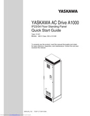
YASKAWA A1000 Series Quick Start Manual (44 pages)
IP23/54 Floor Standing Panel, 400 V Class: 90 to 315 kW
Brand:
YASKAWA
| Category:
Controller
| Size: 4 MB
Table of Contents
Table of Contents
3
Safety Instructions and General Warnings
4
Mechanical Installation
9
Electrical Installation
13
Keypad Operation
22
Start up
24
Parameter Table
29
Troubleshooting
34
Maintenance
38
Safe Disable Input Function
40
YASKAWA A1000 Series Manual (19 pages)
Brand:
YASKAWA
| Category:
Controller
| Size: 3 MB
Table of Contents
Table of Contents
3
Preface and Safety
5
Applicable Documentation
5
Supplemental Safety Information
5
Obtaining Support
5
Product Overview
6
Applicable Models
6
Application Selection
7
Traverse Anti-Phase
7
Basic Concept
7
Limitations
7
Control Modes, Symbols, and Terms
8
Related Parameters and Functions
9
Modified Parameters
9
Additional Parameters
9
Function Text
10
Monitor Function Text
10
Multi-Function Input Settings
10
Multi-Function Output Settings
10
Function Description
11
Machine Parameter Selection
11
Application Example
12
Software and Hardware Configuration for A1000 Traverse
12
Implementation
12
Sample Operating Parameters
12
Master and Slave Output Diagram: Standard Operation
13
Traverse Operation Exceeds Maximum Output Frequency
14
Changing Reference Frequency
14
Traverse Mode Operation with Changing Frequency Reference
15
Revision History
16
YASKAWA A1000 Series Installation Manual (34 pages)
AC Drive
Brand:
YASKAWA
| Category:
Computer Hardware
| Size: 2.05 MB
Table of Contents
Table of Contents
3
Preface and Safety
4
Product Overview
8
Receiving
9
Powerlink Option Components
10
Installation Procedure
13
Powerlink Option Related Drive Parameters
19
Object Dictionary
21
Process Data Objects (PDO)
24
Fault Diagnosis and Possible Solutions
26
Specifications
33
YASKAWA A1000 Series Installation Manual (31 pages)
Motor PG Feedback Line Driver Interface
Brand:
YASKAWA
| Category:
Recording Equipment
| Size: 3.18 MB
Table of Contents
Table of Contents
2
Preface and Safety
3
Product Overview
6
Receiving
7
Option Components
8
Installation Procedure
9
Related Parameters
21
Troubleshooting
24
Specifications
29
YASKAWA A1000 Series Installation Manual (30 pages)
AC Drive, Option, Analog Input
Brand:
YASKAWA
| Category:
DC Drives
| Size: 3.36 MB
Table of Contents
Table of Contents
3
Preface and Safety
4
Product Overview
7
Receiving
8
Option Components
9
Installation Procedure
10
Related Parameters
22
Troubleshooting
26
Specifications
28
YASKAWA A1000 Series Manual (36 pages)
AC Drive
Brand:
YASKAWA
| Category:
DC Drives
| Size: 1.71 MB
YASKAWA A1000 Series Installation Manual (24 pages)
AC Drive Option, 120 Vac Digital input
Brand:
YASKAWA
| Category:
Controller
| Size: 1.98 MB
Table of Contents
Table of Contents
3
Preface and Safety
4
Product Overview
7
Receiving
8
Option Components
9
Installation Procedure
10
Troubleshooting
21
Specifications
22
YASKAWA A1000 Series Setup (4 pages)
TCP Modbus Communication
Brand:
YASKAWA
| Category:
Media Converter
| Size: 0.89 MB
Advertisement
Related Products
YASKAWA A1000 HHP
YASKAWA A14
YASKAWA AO-A3
YASKAWA APMC-CP2700-E
YASKAWA AI-A3
YASKAWA ANTAIOS
YASKAWA A02
YASKAWA SGDV AE5A Series
YASKAWA ACS-500
YASKAWA AI-V3/J
YASKAWA Categories
Controller
DC Drives
Servo Drives
Robotics
Control Unit
More YASKAWA Manuals
Login
Sign In
OR
Sign in with Facebook
Sign in with Google
Upload manual
Upload from disk
Upload from URL