Sign In
Upload
Manuals
Brands
Safran Manuals
Receiver
CORTEX Series
Safran CORTEX Series Manuals
Manuals and User Guides for Safran CORTEX Series. We have
1
Safran CORTEX Series manual available for free PDF download: User Manual
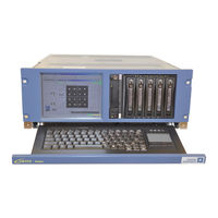
Safran CORTEX Series User Manual (382 pages)
HIGH DATA RATE RECEIVER
Brand:
Safran
| Category:
Receiver
| Size: 11.15 MB
Table of Contents
Table of Contents
3
Symbols Description
22
Ce Marking
23
Weee Directive
24
Caution
24
Important Safety Instructions
25
General
25
Grounding & Electrical Installation Standards
25
Risk of Electric Shocks
26
Installation, Environment
27
Esd Protective Measures
27
Cleaning, Maintenance
28
International Security Statements
28
Cortex Hdr Overview
29
Scope
29
Cortex Hdr Main Features
30
Mission of the Cortex Hdr
31
Introduction
31
Operating Modes
31
Telemetry Demodulation
32
Telemetry Processing
32
Polarization and Antenna Combining
33
Simulation & Self-Testing
33
Cortex Hdr Architecture
34
Functional Block Diagram of a Demodulation Channel
34
Figure 1: CORTEX HDR Demodulation and Ingestion Functional Block Diagram
34
Functional Block Diagram of a Modulation Channel
35
Figure 2: CORTEX HDR Test Modulator Functional Block Diagram (Single Channel, Single IF)
35
Figure 3: CORTEX HDR Test Modulator - Multi Channel, Multi if Operation
35
CORTEX HDR Hardware Architecture
36
Figure 4: CORTEX HDR Hardware Block Diagram
36
PC-Compatible Workstation
37
Figure 5: Example of CORTEX HDR Workstation
37
Test Modulator Board
38
Demodulator Board
38
I/O Connectors
38
CORTEX HDR Software
39
Local or Remote M&C
39
Password Protection
39
Software Version
40
Figure 6: MCS Software Version
40
Cortex Hdr Interfaces
41
Mechanical & Electrical Interfaces
41
Ethernet TCP-IP Interface
41
Table 1: CORTEX HDR TCP-IP Port Addresses
41
FTP Interface
42
Figure 7: CORTEX HDR TCP-IP Interfaces
42
Cortex Hdr Performances
43
Demodulation Unit
43
IF Reception
43
Demodulation
44
Implementation Loss
45
Bit Synchronization
46
Filtering
47
Viterbi Convolutional Decoding
48
Viterbi ½
48
Viterbi ¼
48
Scrambler
49
Transport Layer (RS-DVB or Asynchronous LDPC Layer)
49
Bem 4D 8Psk Tcm Dvb-S R-S
50
VHR-DVB-S2 and CCSDS-SCCC Standard
50
OQPSK/8PSK Variable Modulation
50
Diversity Combining Unit and Antenna Combining
51
Data Processing Unit
51
Frame Synchronization
51
Data Time-Tagging
51
CRC Frame Checking
51
CCSDS and ECSS Decoding
52
LDPC Decoding
52
Data Output
52
Data Storage
53
Playback
54
Test Modulator
54
IF Modulation
54
Noise Source
54
Modulation
54
PCM Simulation
55
Doppler Simulation
55
Start-Up Menus
55
Frequency Reference
56
External Reference
56
Internal Reference
56
Time Code Reference
56
Mechanical - Environment
56
Supply
57
Hardware Description
58
Cortex Hdr Integration
58
Hardware Configuration
58
PC-Compatible Workstation
58
Demodulator Board
59
Overview
59
Separate if Inputs
59
Figure 8: Demodulator Input Stage with Separate if Inputs
59
Test Modulator Board
60
Figure 9: CORTEX HDR Test Modulator - Multi Channel, Multi if Operation
60
I/O Connectors Definition
61
CPU Board I/Os
61
Demodulator & Test Modulator I/Os
61
HDR 4G/4G+ I/Os
61
Figure 10: CORTEX HDR 4G/G+ I/Os
61
Demodulator I/Os
62
Table 2: Demodulator I/Os Definition
63
Channel a & Channel B I/Os Description
65
Table 3: Data & Clock Outputs Vs Demodulation
66
Table 4: Data & Clock CADU Outputs
67
Table 5: Data & Clock Outputs Vs Demodulation (Soft Outputs) Hardware Menu Dependent
67
Figure 11: Soft Decision Coding Vs I/Q Constellation (Normal Soft Output)
68
Figure 12: Soft Decision Coding Vs I/Q Constellation (Merge Soft Output)
69
AIT Connector (LVDS Data Output - J73) Description
70
Table 6: Data and Clock Outputs on J73
70
Demodulator Inputs Description
71
Table 7: Single Channel Demodulator Input Modes
71
Table 8: Dual Channel Demodulator Input Mode
71
Test Modulator I/Os
72
Table 9: Modulator I/Os Definition
72
Output Data Definition and Timing
73
Timing for All Output Types
73
I/Q Merged Output
74
Split 2 Output (I and Q Normal Output)
74
Split 4 Output
75
CADU Output Formats
75
Specific I/Os (Customers Requirements)
76
Functional Description
77
Monitoring & Control
77
Monitoring
77
Control
77
Logging
77
Demodulation
78
IF Processing
78
Bit Synchronization
78
Signal Processing
78
Customized FIR Filters
79
General
79
Custom Filters Programming
79
DEAF Filtering
80
General
80
Principle of the DEAF
81
Use of the DEAF
81
Figure 13: Effect of the DEAF
82
XDEAF for Reception of Dual Polarization Data Transmission
83
Adjacent Channel Rejection
85
Figure 14: Effect of the XDEAF
85
Viterbi Convolutional Decoding
86
General
86
Single or Dual Viterbi Decoder
87
Figure 15: Viterbi Decoding Module. Single & Dual Operating Modes
87
Parallel Viterbi Decoders
88
Figure 16: Parallel Viterbi Decoding Module
88
Punctured Viterbi
89
Figure 17: Viterbi De-Puncturing Process
89
Figure 18: Punctured Viterbi BER Performances
90
PCM Decoding
91
DNRZ, QPSK Decoding (DQPSK)
91
CCSDS Recommended DNRZ Code in QPSK Mode
91
Other Possibilities for DNRZ Codes in QPSK Mode
92
DQPSK Configuration
92
DNRZ, OQPSK Decoding
93
Most Commonly Used DNRZ Code in OQPSK Mode
93
Other Possibilities for DNRZ Codes in OQPSK Mode
94
DOQPSK Configuration
94
I/Q Shift Compensation in OQPSK Mode
95
CCITT V.35 De-Scrambler
95
BEM: 4D-8PSK-TCM-DVB-S Reed Solomon Decoding
95
Introduction
95
8PSK-TCM Coder
96
Differential Coder
97
Figure 19: Structure of the 4D 8PSK-TCM Coder/Mapper
97
Table 10: Bit Mapping for Differential Coder
97
Convolutional Coder
98
Figure 20: Differential Coder and Modulo-8 Adder Principle
98
Figure 21: Convolutional Coder Recommended for High Data Rates
98
Constellation Mapper for 4D-8PSK-TCM
99
Figure 22: Constellation Mapper for 2 Bits/Channel-Symbol
99
Figure 23: Constellation Mapper for 2.25 Bits/Channel-Symbol
100
Figure 24: Constellation Mapper for 2.5 Bits/Channel-Symbol
101
Figure 25: Constellation Mapper for 2.75 Bits/Channel-Symbol
101
Coder/Mapper Implementation at 2, 2.25, 2.5 & 2.75 Bits/Channel-Symbol Efficiency
102
Figure 26: Coder and Mapper Implementation at 2 Bits/Channel-Symbol Efficiency
102
Figure 27: Coder and Mapper Implementation at 2.25 Bits/Channel-Symbol Efficiency
102
Figure 28: Coder and Mapper Implementation at 2.5 Bits/Channel-Symbol Efficiency
103
Figure 29: Coder and Mapper Implementation at 2.75 Bits/Channel-Symbol Efficiency
103
DVB-S Transport Layer: Reed Solomon Code
104
Synchronized Randomization
104
Figure 30: Concatenation Principle
104
Reed-Solomon Encoding
105
Packets Interleaving and Synchronization Byte Insertion
105
Figure 31: Randomization Principle
105
Interface between Trellis Coded Symbols and Bytes
107
Figure 32: Data Arrangement in TCM 2.5 Bits/Channel_Symbol
107
PRN-BER Computation
108
BER on Separate I & Q Channels
108
BER on Merged I & Q Channels
108
Digital Outputs
109
Figure 33: BER Measurement Methods: Tested Ambiguities and GUI Display
109
Doppler and Integrated Phase Measurement
110
Introduction
110
Required Setup for Optimal Performance
110
Sampling Rate
111
Accumulated Phase Format
112
Table 11: Counter Capacity and Resolution at 720Mhz
113
Table 12: Counter Capacity and Resolution at 1.2Ghz
114
Displaying the Carrier Offset of the Doppler Port in the DMU Window
115
Interpolation Process
116
Doppler Computing
116
Impact of Phase Errors on Doppler Computing
117
Sampling Period Resolution
117
Error Due to Computing
117
Error Due to Floating Representation
118
Es/N0 Estimators in DVB-S2 and SCCC Environment
118
Warning
118
Standard Es/N0 Estimation
118
Figure 34: Typical Es/N0 Estimation over the Constellation
118
Figure 35: Estimator Behavior VS Es/N0 and Modulations
119
Figure 36: Standard Es/N0 Estimate in the GUI
119
Data-Aided Es/N0 Estimation in SCCC and DVB-S2
120
Figure 37: Standard Es/N0 Estimate in the Vector Pane
120
Figure 38: Data-Aided Estimation of Es/N0
121
Figure 39: Data-Aided Estimator in the GUI, Physical Layer Pane of the Demodulator
122
Data Processing
123
Functional Breakdown of the Data Processing Unit
123
Figure 40: Data Processing Unit Block Diagram
123
Frame Synchronization & Ambiguity Resolution
124
Frame Synchronization Strategy
124
Figure 41: Frame Synchronization Process
125
CCSDS Data De-Randomizer
126
Customized Data De-Randomization
127
CRC Frame Checking
128
(255,223) Reed-Solomon Decoding
128
(255,239) Reed-Solomon Decoding
129
(10,6) Reed-Solomon Frame Header Decoding
129
Specific Decoding
129
LDPC Decoding
130
Introduction
130
LDPC 7/8 for Near-Earth Applications
130
AR4JA LDPC ½, 2/3, 4/5 Codes for Deep Space Applications
130
Implementation
130
Performances
131
Recording and Data Transmission over Ethernet
131
General Consideration
131
Data Storage
131
TCP-IP Data Recovery
132
Figure 42: Data Transmission over TCP-IP. Message Formatting
132
Archiving and FTP Recovery
133
Generality
133
Overview
133
Data Files Structure
134
Report Files Structure
134
Figure 43: Recorded Data File Structure
134
Standard FTP CCSDS Mode
135
Figure 44: CCSDS FTP Mode Storage Directories
136
FTP User Defined Mode
137
Playback Function
138
Operating Modes
138
Figure 45: Playback Function: Test Modulator Operating Mode
138
Figure 46: Playback Function: Test Modulator Data + Clock Mode
138
Sources of the Data to Replay
139
Multi-DPU Processing
139
Generality
139
Figure 47: QPSK Demodulation with 2 DPU
140
Figure 48: QPSK or 16QAM Demodulation with 4 DPU
141
Figure 49: 16QAM Demodulation with 8 DPU
142
Figure 50: QPSK or 16QAM Demodulation with 1 DPU
143
Figure 51: QPSK Demodulation with 2 DPU
143
Ambiguity Resolution by the Dpus
144
Figure 52: 8 DPU Data Flow for Automatic Ambiguity Resolution
144
BER Measurements
145
Data Output
146
Guide for Multi DPU Operation
147
Polarization Combining
152
General
152
Data Path
152
Signal Processing
153
Test Modulation
155
Data Generation
155
Data Sources
155
Pseudo Random Data
155
Figure 53: Data Generation Scheme
155
Data from File
156
File Format
156
Cycle Length
156
Figure 54: 10-Bit Generator with Feedbacks after Register 3 and 0
156
Table 13: PRBS Generators for BER Analysis
156
External Data & Clock (Input Format)
157
Playback
157
Internal and External Framing
157
Framing Features
157
Framing and Cycle Length
158
Encoding
158
Scrambling
158
Figure 55: Frame Aligned with File
158
Fecf
159
Modulation Unit
159
Main Features
159
Constellation Mapping
159
Figure 56: 16APSK Mapping 1
162
Figure 57: 16APSK Mapping 2
162
DNRZ Coding
164
Multi-DGU Support
165
Figure 58: Example of 2 Dgus Merging for Simulation of Independent I/Q Transmission in QPSK
165
Figure 59: Example of 3 Dgus Merging for Simulation of Independent I/Q/C Transmission in 8PSK
166
Figure 60: Example of 3 Dgus with Different Offsets
166
Dvb-S2 & Sccc
167
IF Signal Generation
167
IF1 and IF2
167
Figure 61: if Signal Generation
168
Figure 62: GUI: if Unit
169
Figure 63: Example 1: 2 Adjacent Channels on IF1 - 1 Single Channel on IF2
170
Figure 64: Example 1: 2 Adjacent Channels on IF1 - 1 Single Channel on IF2 (GUI)
170
Figure 65: Example 2: 3 Adjacent Channels on IF1 - Nothing on IF2
171
Figure 66: Example 2: 3 Adjacent Channels on IF1 - Nothing on IF2 (GUI)
171
Figure 67: Example 3: 1 Channel on IF1 - 1 Channel on IF2
172
Figure 68: Example 3: 1 Channel on IF1 - 1 Channel on IF2 (GUI)
172
Doppler
173
Modulation of External Data
173
Direct Input to the Modulator
173
Principle
173
Figure 69: ECL Inputs on Test Modulator Board - Single Ended ECL
173
Figure 70: ECL Inputs on Test Modulator Board - Differential ECL
173
Table 14: Modulations and Input Modes
174
Table 15: Connectors Allocation, Single Ended ECL
174
Figure 71: IQZ Mapping Example
175
Table 16: Connectors Allocation, Differential ECL
175
Configuring the Modulator and the Format Input
176
Figure 72: Direct Modulator Input, as Seen in the Main Modulator Window
176
BER Estimation
177
MCS Preset Files
177
Figure 73: 100 Mbps, QPSK Direct Input Setting
177
Constraints
178
Cable Equalizer Filter
179
Figure 74: Example of Non-Linearity in a RG188A/U Cable
179
Figure 75: Example of Cable Compensation
180
Data Logging
181
Standard Loging
181
Extended Logging
182
System Logging
184
Operating Manual
185
Starting and Configuring the Cortex Hdr
185
First Steps
185
Starting the PC Workstation
185
Signal Processing Software. Start-Up Menu
185
Starting the Monitoring & Control Software
185
Factory Configuration
185
Software Exit & CORTEX HDR Shutdown
186
Exiting the Monitoring & Control Software
186
Exiting the Signal Processing Software
186
Restarting the SPS & MCS
186
CORTEX HDR Shutdown
186
Screen Saver
186
Signal Processing Software (Sps)
187
CTX Documents
187
SPS Start Sequence
187
Figure 76: SPS Start Sequence
187
Configuring the CORTEX from CTX Documents
188
CTX Document Name Table
188
CTX Document Storage and Loading
188
Start-Up Menu Selection by Remote Access Control (RAC)
189
General
189
Figure 77: CTX Document Management
189
MCS Graphical User Interface
190
Figure 78: MCS Menu Management Window
190
Menus Description File
191
CORTEX HDR-4G Licenses and Basic Menus
192
Table 17: the Basic Demodulator Menus of the CORTEX HDR
194
Table 18: the Basic Test Modulator Menus of the CORTEX HDR
196
4G / XXL / XL Demodulator Menus Equivalence
197
XL with XXL and 4G
197
XXL with 4G
198
4G / XXL Test Modulator Menus Equivalence
201
SPS Version Identification
202
Common Data
202
CORTEX HDR Specific Data
202
Figure 79: about CORTEX SPS Version
202
CORTEX HDR System Parameters in Registry
203
CORTEX Station
203
Menus Description
203
Last Used Menu
203
RAC Port Number
203
Demodulation Unit
203
Output Clock ON/OFF
203
Punctured Viterbi Setting
204
BER on Merged or Separate I/Q
204
High Ebno Tracking Mode
204
I/Q Synchronization in Capture Mode (Menu # 7)
204
DNRZ PCM Decoding (Deprecated)
205
OQPSK (SQPSK) Algorithm
205
DVB-S2 Randomization Polynomial
205
Transport Layer: Frame Synchronizer Setting
205
Check to Lock Strategy (CTL) for RS DVB
205
Lock to Search Strategy (LTS) for RS DVB
206
Synchronization Threshold (SYN) for RS DVB
206
Synchronization Word for RS DVB
206
Idle Synchronization Word for RS DVB
206
Frame Size for RS DVB
206
Control of the R-S DVB Decoding Chain for RS DVB
207
Check to Lock Strategy (CTL) for LDPC
207
Lock to Search Strategy (LTS) for LDPC
207
Synchronization Threshold (SYN) for LDPC
207
Derandomization for LDPC
207
Synchronization Word LSB for LDPC
207
Synchronization Word MSB for LDPC
208
Synchronization Mask LSB for LDPC
208
Synchronization Mask MSB for LDPC
208
Synchronization Word Length for LDPC
208
Decoder Refresh Period
208
Transport Layer Status
209
Test Modulation Unit
209
Selecting the DNRZ Code in QPSK and OQPSK Modulation Mode
209
Global HDR
209
Selecting LVDS / ECL Inputs of the Test Modulator
209
Recording in Raw Data Mode
209
DMX Table
210
TCP/IP Data Transmission
210
TCP/IP Playback Data Reception
210
Monitoring & Control Software (Mcs)
211
General
211
MCS Documents
211
MCS Start Sequence. MCS Control Status
212
Figure 80: MCS Start Sequence
212
M&C Session. MCS Documents Management
214
Close the Active M&C Session
214
Open an M&C Session with a CORTEX
214
Save the CORTEX Configuration to an MCS Document on the Disk
214
Reconfigure the CORTEX from an Existing MCS Document
214
Graphical User Interface
215
MCS Login Window
215
Figure 81: MCS Top-Level Window
215
Figure 82: MCS Login Window
215
MTDI (Multiple Tabbed Document Interface)
216
Figure 83: Multiple Tabbed Document Interface
216
Upper Toolbar
217
Common Data
217
Lower Toolbar
219
Common Data
219
CORTEX HDR Specific Data
220
Bottom Status Toolbar
221
CORTEX Monitoring & Configuration
221
Default Operating Mode
221
CORTEX Configuration
221
Forced Connection to the Control Port (Pseudo Local Mode)
222
OK/DIFFER Management Mode
222
Standard Mode
222
Protected Mode
223
Automatic Mode
223
MCS Version Identification
224
Changing a Password
224
Figure 84: Cortex MCS About: Software Version
224
MCS Interface for CTX Document Management
225
Figure 85: Changing a Password
225
MCS Interface for User MCS Files Loading
226
MCS File System Architecture
227
MCS System Parameters in Registry
227
Monitoring
227
Monitoring Rate
227
MCS Auto-Connect
227
Auto Connect ON/OFF
227
Auto Connect Time-Out
228
Auto Connect Retry
228
MCS Preferences
228
Synchronization Word: Bit Masking Convention
228
Operating System and Files Architecture
229
Introduction
229
Files Architecture
229
Files Associated with Monitoring & Control Software
229
Files Associated with the Signal Processing Software
229
Files Associated with the Cortex HDR Hardware
230
Other Files
230
Windows 7 Tools & Functionalities
230
Cortex Hdr Gui
232
Conventions &Warnings
232
Graphical User Interface. Windows Breakdown
233
Figure 86: Graphical User Interface: Windows Breakdown
233
CORTEX HDR Top-Level Windows
234
Global" Window
234
CORTEX HDR Architecture & Global Status
234
Figure 87: CORTEX HDR: Global Window
234
Global Engineering Window
236
Figure 88: Global Engineering Window
236
TCP-IP Secondary Window
237
Figure 89: TCP-IP Secondary Window
237
Time" Window
238
Figure 90: CORTEX " Time " Window
238
Control
239
Monitoring
239
NTP Cilent Set-Up
239
Time Management Procedures
240
Loss of Time Code or Time Code Missing
240
Leap Second Management
240
Figure 91: Leap Second Management
241
Absolute Time Reference
242
Absolute Reference Time & Leap Second Management
243
Config" Window
244
Control
244
Figure 92: CORTEX HDR: Config. Window
244
Figure 93: Configuration Help Window for the Demodulator
246
Figure 94: Configuration Help Window for the Test Modulator
246
Monitoring
247
Project" Window
248
Control
248
Monitoring
248
Figure 95: CORTEX HDR: Project Window
248
Information" Window
249
Figure 96: CORTEX HDR: Information Window
249
Mod" Window
250
Figure 97: "Mod" Window
250
Modcnf" Window
251
Figure 98: "Modcnf" Window
251
Demodulator Windows
252
Global" Window
252
Figure 99: Demodulator: Global Window for QPSK Modulation + I & D Filter
252
Figure 100: Demodulator: Global Window for QPSK Modulation + Raised Cosine Filter
252
Figure 101: Demodulator: Global Window for QPSK Modulation + Custom Filter
253
Figure 102: Demodulator: Global Window for OQPSK Modulation
253
Figure 103: Demodulator: Global Window for GMSK Modulation
254
Figure 104: Demodulator: Global Window for SOQPSK Modulation
254
Figure 105: Demodulator: Global Window for UQPSK Modulation
255
Figure 106: Demodulator: Global Window for 8PSK Modulation
255
Figure 107: Demodulator: Global Window for 16QAM Modulation
256
Figure 108: Demodulator: Global Window for 16APSK Modulation
256
Figure 109: Demodulator: Global Window for 32APSK Modulation
257
Figure 110: Demodulator: Global Window for 64APSK Modulation
257
Figure 111: Demodulator: Global Window for VCM QPSK / 8PSK
258
Figure 112: Demodulator: Global Window for DVB-S2 /SCCC
258
Figure 113: Demodulator: Global Window for Multi-DPU Operation
259
Control
260
IF Processing
260
Flow ID. (Hex)
265
Matched Filter
265
Optional Rejection Filter
266
Monitoring
266
Upper Banner
266
Other Status & Alarms
267
Physical Layer" Window
268
Figure 114: Demodulator: Physical Layer Window for SCCC and DVB-S2 Standard
268
Control
269
Monitoring
270
Physical Layer Status" Window
271
Monitoring
271
Figure 115: Demodulator: Physical Layer Status Window for SCCC and DVB-S2 Standard
271
BER" Window
272
Figure 116: Demodulator: BER Window PRN Mode
272
Figure 117: Demodulator: BER Window File Mode
272
Control
273
Monitoring
273
Upper Banner
273
Other Status & Alarms
273
Decoding" Window
275
Figure 118: Demodulator: Decoding Window for BPSK Modulation
275
Figure 119: Demodulator: Decoding Window for QPSK & OQPSK Modulation (Viterbi Single)
275
Figure 120: Demodulator: Decoding Window for QPSK & OQPSK Modulation (Viterbi Dual)
276
Figure 121: Demodulator: Decoding Window for UQPSK Modulation
276
Figure 122: Demodulator: Decoding Window for 8PSK Modulation
277
Control
278
Monitoring
280
Upper Banner
280
Other Status & Alarms
280
Spectrum" Window
281
Figure 123: Demodulator: Spectrum Window
281
Vector" Window
283
Figure 124: Demodulator: BPSK Vector Window
283
Figure 125: Demodulator: QPSK(OQPSK) Vector Window
284
Figure 126: Demodulator: 8PSK Vector Window
284
Figure 127: Demodulator: 16QAM Vector Window
285
Figure 128: Demodulator: 16APSK Vector Window
285
Figure 129: Demodulator: 32APSK Vector Window
286
Filter" Window
287
Figure 130: Filter: Time Display Selection
287
Figure 131: Filter: Frequency Display Selection
288
Data Processing Unit Windows
290
CADU" Window
290
Control
290
Figure 132: DPU: CADU Window
290
Monitoring
294
Upper Banner
294
Frame Synchronizer Status
294
Reed Solomon Decoders Status
294
LDPC Status
295
CRC Status
295
Control (Transport Layer Window)
296
Figure 133: DPU: Transport Layer Window (R-S DVB Mode)
296
Monitoring (Transport Layer Window)
297
BER" Windows
297
Figure 134: DPU: BER Window
297
Control
298
Monitoring
298
Real Time Frame" Window
299
Control
299
Figure 135: Data Processing Unit: Real Time Frame Window
299
Monitoring
300
TCP-IP Status
300
Frame Sync. Status
300
Upper Banner
300
Quick Look" Window
301
Control
301
Figure 136: Data Processing Unit: Quick Look Window
301
Telemetry Blocks Quick Look
302
Figure 137: Telemetry Block Description
302
Monitoring
303
Upper Banner
303
Polarization Combining Windows
304
Global" Window
304
Control
304
Figure 138: Polarization Combining: Global Window
304
Monitoring
305
Other Status and Alarms
306
BER" Window
306
Decoding" Window
306
Vector" Window
306
Data Recording Unit Windows
307
Global Disk and Memory Management" Window
307
Figure 139: Global Disk & Memory Management Window (Configuration)
307
Figure 140: Global Disk & Memory Management Window (Status)
307
Control
308
Monitoring
311
Recording Global" Window
312
Control
312
Figure 141: DRU: Recording Global Window
312
Monitoring
314
Upper Banner
314
Recorder Status
314
FTP" Window
315
Figure 142: DRU: FTP Window (Generic)
315
Control
316
Figure 143: DRU: FTP Window (CCSDS Standard)
316
Monitoring
318
Session Status
318
Upper Banner
318
Virtual Channels" Window
319
Control
319
Monitoring
319
Virtual Channels Information
319
Upper Banner
319
Figure 144: DRU: Virtual Channels Window
319
Test Modulator Windows
320
Data Generation Unit" Windows
320
Data" Window
320
PRN Selection
320
Figure 145: PRN Selection
320
File Selection
321
File I/Q Selection
321
Figure 146: File Selection
321
Figure 147: File I/Q Selection
321
Control
322
Internal Framing" Window
322
General Selection
322
Figure 148: Internal Framing Window
322
Control
323
External Framing" Window
324
General Selection
324
Control
324
Figure 149: External Framing Window
324
Status & Warnings
325
Modulation Unit" Windows
325
Modulation" Window
325
Bpsk/Qpsk/Gmsk
325
Figure 150: Pointing at an Error
325
Figure 151: BPSK/QPSK/GMSK Configuration
325
Oqpsk
326
Uqpsk
326
Figure 152: OQPSK Configuration
326
Figure 153: UQPSK Configuration
326
8Psk
327
16Qam
327
Figure 154: 8PSK Configuration
327
Figure 155: 16QAM Configuration
327
16Apsk
328
Figure 156: 16APSK Configuration
328
Figure 157: 32APSK Configuration
328
64Apsk
329
Viterbi Mode
329
Figure 158: 64APSK Configuration
329
Figure 159: Viterbi Configuration
329
TCM Mode
330
Control
330
Figure 160: TCM Configuration
330
Physical Layer" Window
332
SCCC Mode
332
DVB-S2 Mode
332
Figure 161: SCCC Configuration
332
Figure 162: DVB-S2 Configuration
332
Control
333
Status & Warnings
333
Figure 163: Status: Input of the MDU
333
Figure 164: Modulation Type
334
Figure 165: Pointing at an Error
334
IF Unit" Windows
335
IF" Window
335
General Selection
335
Control
335
Figure 166: if Window
335
Doppler/Xpol" Window
336
Doppler Configuration
336
XPOL Configuration: Still
336
Figure 167: Doppler Configuration
336
Figure 168: XPOL Configuration: Still
336
XPOL Configuration: File
337
Control
337
Figure 169: XPOL Configuration: File
337
Status and Warnings
339
Figure 170: if Warnings
339
Figure 171: Eb/N0 Status
339
Figure 172: Doppler Status
339
Figure 173: XPOL Status
339
Format Input" Windows
340
Format Input" Window - Merged BER
340
Figure 174: Serial Data
340
Figure 175: Data //4
340
Format Input" Window -SPLIT BER
341
Figure 176: Hard Symbol, BPSK
341
Figure 177: Hard Symbol, OQPSK/QPSK
341
Figure 178: Hard Symbol, 8PSK
342
Figure 179: Hard Symbol, 16APSK/16QAM
342
Control
343
Figure 180: Data //4
343
Status & Warnings
344
Error Insertion
344
Figure 181: Status: Clock Status, Locked and Unlocked
344
Figure 182: Clock and Raw Bitrate Estimates
344
Figure 183: BER and Errors Status
344
Figure 184: Pointing at an Error
344
Playback Windows
345
Global" Window
345
Configuration and Control
345
Figure 185: Playback: Global Window
345
Status
346
Specific Operating Mode: Playback LAN
347
Figure 186: Playback LAN: Global Window
347
Figure 187: Playback LAN: "Reset Playback Client" Button in "TCP-IP Clients" Window
348
Figure 188: Playback LAN: "Acquisition" and "Stop All" Buttons in the Toolbar
348
File" Window
349
Figure 189: Playback: File Window in Report TM Mode (by Date)
349
Figure 190: Playback: File Window in Report TM Mode (by Number)
349
Figure 191: Playback: File Window in Playback Data File Mode
350
Figure 192: Playback: File Window in BER File Mode
350
Figure 193: Playback: File Window in Recorded Frames Mode
351
Figure 194: Playback: File Window in Playback LAN Mode
351
Configuration
352
File Selection
353
Specific Operating Mode: Playback LAN
354
Figure 195: Playback LAN: Overrun Option
354
Logging Windows
355
Data Logging Control" Window
355
Control
355
Status
355
Figure 196: Logging Status Window
355
Data Logging Editor" Window
356
Figure 197: Logging Editor Window
356
Extended Logging Windows
358
Maintenance Procedures
359
General
359
Mechanical Inspection and Cleaning
359
Handling Precautions
359
CPU Load Considerations
359
Software Loading
359
Functional Investigation
360
Demodulator Check
360
Viterbi Check
360
Demodulator Output Ports
360
Interpretation of the Vector Display
361
Hardware Investigation & Repair
366
LED Indicators
366
Test Modulator Board
366
Demodulator Board
366
CPU Board
366
Ipmimonitor Tool. Temperature Alarm
366
PC Workstation Maintenance
367
Software Upgrade & Installation
368
Loading or Upgrading the IN-SNEC Software
368
Complete Software Re-Installation
368
Satellites Configuration Examples
369
Annex 1: Cortex Hdr Ethernet Interface
378
Annex 2: Demodulator Board
379
Annex 3: Test Modulator Board
380
Annex 4: Pc-Compatible Workstation
381
Annex 5: Project-Specific Data
382
Advertisement
Advertisement
Related Products
Safran CORTEX RTR NeXt Series
Safran CORTEX CRT Quantum
Safran CMM 25
Safran CMM 63
Safran CMM 68
Safran RTR-NeXt
Safran RX-1
Safran Categories
Network Hardware
Measuring Instruments
Touch terminals
Motherboard
IP Access Controllers
More Safran Manuals
Login
Sign In
OR
Sign in with Facebook
Sign in with Google
Upload manual
Upload from disk
Upload from URL