Sign In
Upload
Manuals
Brands
Safran Manuals
Modem
CORTEX CRT Quantum
Safran CORTEX CRT Quantum Manuals
Manuals and User Guides for Safran CORTEX CRT Quantum. We have
1
Safran CORTEX CRT Quantum manual available for free PDF download: User Manual
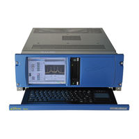
Safran CORTEX CRT Quantum User Manual (346 pages)
COMMAND RANGING & TELEMETRY UNIT
Brand:
Safran
| Category:
Modem
| Size: 9.41 MB
Table of Contents
Table of Contents
5
Crt Quantum
16
Table 1: Serial Models for the Table 2: Ethernet Portsa
28
Figure 1: Cortex Crt Quantum Functional Block Diagram
32
Figure 2 : Hardware Architecture
33
Figure 3: Chassis IS00427 Front Panel Appearance (Front Panel Color Not Contractual)
34
Figure 4: Chassis IS00452 Front Panel Appearance (Front Panel Color Not Contractual)
35
Figure 5: Downlink Input Signal Selection
36
Figure 6: CRT Quantum, CRT XL and CRT XL2 Comparison Chart
43
Window
43
Integration Time
43
Figure 7: Tcp-Ip Interfaces
68
Table 3: Udp Ports Addresses
69
Figure 8: Integrated Simplified Interconnection Panel on Is00427
70
Figure 9: Integrated Simplied Interconnection Panel on Is00452
70
Figure 10: 3U Full Interconnection Panel
71
Figure 11: Ribbon Cable Connection and Securing
71
Table 4: I/O Connector Panel
76
Table 5: I/O Connector Panel
80
I/O Connectors Description
81
External Interconnection Panel
81
Industrial Computer Rear Panel Description
81
Chassis 4U IS00427
81
Configuration SM01037242C: COMSAT 4U Without EFC
81
Figure 12: Is00427 Rear Panel Connectors with Bnc Integration
81
Table 6: Is00427 I/O Connector
81
Configuration SM01037242C: COMSAT 4U with EFC
82
Figure 13: Is00427 Rear Panel Connectors with Bnc Integration and Efc
82
Table 7: Is00427 I/O Connector
83
Configuration SM01037243D: Agencies / AIT 4U Without EFC
84
Figure 14: Is00427 Rear Panel Connectors with Bnc Integration and External I/Oconnectors
84
Table 8: Is00427 I/O Connector
85
Integrated Panel
86
Configuration S107583 : Agencies / AIT 4U with EFC
86
Figure 15: Is00427 Rear Panel Connectors with Bnc Integration , External I/Oconnectors and Efc
86
Table 9: Is00427 I/O Connector
87
Chassis 2U IS00452
88
Configuration S100684: COMSAT 2U Without EFC
88
Figure 16: Configuration S100684 Rear Panel Connectors
88
Table 10: Configuration S100684 R
88
Configuration S100685: Agencies / AIT 2U Without EFC
89
Figure 17: Configuration S100685 Rear Panel Connectors
89
Table 11: Configuration S100685 R
89
Configuration S100686: COMSAT 2U with EFC
90
Figure 18: Configuration S100686 Rear Panel Connectors
90
Table 12: Configuration S100686 R
90
Configuration S100687: Agencies / AIT with EFC
91
Figure 19: Configuration S100687 Rear Panel Connectors
91
Table 13: Configuration S100687 R
91
Test Points Configuration
92
Video Test Points
93
Table 14: Interconnection Panel
93
TTL and RS422 Data I/Os
95
Table 15: Interconnection Panel
95
Figure 20: DA-15 Female Connector, Front View
96
Table 16: Interconnection Panel
96
Figure 21: Rs-422 Interface
97
Functional Description
98
Monitoring & Control
99
Monitoring
99
Standard Monitoring Protocol
99
Table 17: the Functionalu
99
Low Bandwidth Monitoring Protocol
100
Control
100
Logging
101
General
101
Storage of Logging Data
101
Additional Flows Logging
101
If Demodulation & Telemetry Processing
102
Demodulation Capability
102
Low & High Bandwidth TMU
102
Table 18: Demodulation Capabilities
102
Demodulation Without Sub-Carrier
103
Table 19: Performance Limitation for Table 20: Performance Limitation for
103
Table 21: Performancel
105
Constellation Convention
106
AQPSK Processing
106
GMSK Demodulation
107
SOQPSK Demodulation
108
8PSK Demodulation
109
FM Demodulation
110
FM Discriminator
110
Table 22: Cartesian - to -Polars
111
PCM/FM Modulation
112
Time Code Decoding & Data Time-Tagging
113
Supported PCM/FM Demodulators
113
Reference Frequency
114
External Reference
114
Internal Reference
114
Multi-Symbol PCM/FM Demodulator - Parameters Recommended Setting
114
Introduction
114
Modulation Index
114
Optional RF Stage
115
Down Convertor Specifications
115
Up Convertor Specifications
115
Synthesizer Specifications
116
Mechanical - Environment
116
Supply
116
Propagation Factor
116
IF Level Measurement
117
Low Bandwidth TMU
117
Installation
118
IF Carrier Acquisition
118
Acquisition Algorithms
118
FFT - Wide Spectrum
118
FFT - Narrow Spectrum
118
Scanning Sweep
118
Highest Spectrum Line
118
Shipping
119
Center Spectrum Line
119
Hardware Description
120
Barycentre Frequency
120
Cortex Crt Quantum Integration
121
Mounting of the Boards
121
Network Interfaces
121
CPU Board Ethernet Port
121
Manual Sweep
121
Acquisition By-Pass
121
TCP-IP Interfaces
122
IF Receiver in Video Mode
122
PM and Coherent am Demodulation
122
FM Demodulation
122
By-Pass, Spectrum and Non Coherent am Modes
122
IF Receiver in PCM Mode
123
UDP Interface for Telemetry Data Flow
124
Cortex Connection to the External World
124
Interconnection Panels and Associated Cables
124
PCM/PM Demodulation
124
BPSK, QPSK, OQPSK, SOQPSK GMSK Demodulation
124
AQPSK Demodulation
124
Integrated Simplified Interconnection Panel
125
IF Carrier Tracking
125
Nd Order PLL
125
Full Interconnection Panel (3U)
126
Rd Order PLL
127
Doppler Measurement
128
Sampling Mode
128
Accumulated Phase Format
128
Interpolation Process
129
Doppler Computing
130
Impact of Phase Errors on Doppler Computing
131
Sampling Period Resolution
131
Error Due to Computing
131
Error Due to Floating Representation
132
Diversity Combining
132
General
132
Post Detection Diversity Combining
133
Pre Detection Diversity Combining
134
Outputs
135
Post Detection Diversity Combining
135
Pre Detection Diversity Combining
136
Signal Processing
137
Signal Routing
138
Dual Polarization and Frequency Combining
139
Data Decoding
141
Descrambling
141
Convolutional Decoding
142
8PSK-TCM Decoding
143
Introduction
144
8PSK-TCM Coder
145
Differential Coder
146
Convolutional Coder
147
Constellation Mapper for 4D-8PSK-TCM
148
Reed-Solomon Decoding
149
Turbo Decoding
150
Probability of Bit Error
152
PCM/BPSK/PM (Low or High Bandwidth)
152
PCM/BPSK Square/Pm (Low or High Bandwidth)
153
High Bandwidth Direct PCM (PCM/PM)
153
High Bandwidth Direct PCM (BPSK)
153
LDPC Decoding
153
Ambiguities Solving, I/O Ports & By-Passing Capabilities
156
Low Bandwidth TMU
156
High Bandwidth TMU with Sub-Carrier
157
High Bandwidth Direct PCM: no Viterbi Decoding
159
High Bandwidth PCM: Single Viterbi Decoding
162
High Bandwidth Direct PCM: Dual Dcoding
164
High Bandwidth Direct PCM: DQPSK or DOQPSK
167
High Bandwidth PCM: Dual + Differential Decoding
170
High Bandwidth Direct PCM: AQPSK
173
Frame Synchronization
175
Frame Synchronization Strategy
175
PSK Ambiguity Solving
176
Frame Synchronizer Operating Modes
177
AFL: Anti False Lock
177
Frame Verification
178
Telemetry Frames or Raw Data
178
Telemetry Data Time-Tagging
178
Real-Time of Off-Line Telemetry Server
179
Telemetry Request
179
Telemetry Buffers
179
Telemetry Data Flows
180
Single Frame / Block Transmission
180
Permanent Flow
180
Permanent Flow and Dummy TM
180
Telemetry Data Decommutation
180
Telemetry Data Storage on the Disk
181
Blind Equalization
183
General
183
Deaf
184
Configuration of the DEAF Algorithm
186
Descrambling Mode (LFSR Polynomials)
187
General
187
CCSDS Descrambling
187
Configuration of the Descrambling
187
Continuous Descrambling
188
UTOA (Time of Arrival Precise Measurements)
189
Prerequisites
189
Supported PCM Codes and Channel Encoding
189
Registry Configuration
190
TCP/IP Interface
190
If Modulation & Telemetry Simulation
191
Uplink Resources
191
Low Bandwidth Scenario
192
High Bandwidth Scenario
193
PM and FM Modulation
193
Single PCM Input Signal
193
Video + PCM Input Signals
194
BPSK Modulation
195
QPSK and OQPSK Modulation
196
Without Convolutional Encoding
196
With Single Convolutional Encoding
197
With Dual Convolutional Encoding
197
With Differential Encoding
197
With Dual Convolutional and Differential Encoding
198
AQPSK Modulation
199
Noise Generator Option
200
IFM Output Stage Architecture
200
C/No Adjust
200
Noise Bandwidth
200
Telemetry Simulation
201
General
201
Operating Modes
201
Table 23: Prn Generator Polynomials
202
Encoding
203
Convolutional Encoding
203
Tcm
203
Reed-Solomon
203
Turbo-Code
204
Table 24: Turbo Code
204
LDPC Encoding
206
Table 25: Ldpc Code
206
Uplink Digital Filter
208
General
208
Filter Characteristics
208
Sweeping
211
Satellite Telecommanding
212
General
212
Satellite TC Request
213
Wait & Verify" Instruction with Time-Out and Retry
214
Execute" Instruction
214
Pause" Instruction
214
Wait for Absolute Time" Instruction
214
TCU Unlock" Instruction
214
NOP" Instruction
215
Stop Idling" Instruction
215
Group" Instruction
215
Data + Execute" Instruction
215
Satellite TC Requests and Instructions Sequencing
215
CLCW Checking & if Carrier Sweeping
217
TC Demodulation by a Telemetry Chain
222
Local Satellite Telecommanding Capabilities
223
Telecommand Socket Closure
223
TC Watchdog
223
Activation/Inhibition of the TC Watchdog Mechanism
223
TC Watchdog Mechanism
223
Telecommand Unit Testing
224
COP" Software Package
224
Carrier and Modulation Sequencing
225
Carrier OFF, no Idle Pattern
225
Carrier ON, no Idle Pattern
225
Carrier off and Idle Pattern
226
Carrier on and Idle Pattern
226
Progressive Modulation Index
227
Range Measurement
228
General
228
Supported Standards
228
Ranging Ports
228
Local" Ranging Client
228
Continuous Mode (All Modes Except INMARSAT and LMCO)
229
Ranging Sequence (All Modes Except INMARSAT and LMCO)
230
Frequency Programming
231
Major Tone Frequency
232
Minor Tone Frequencies (ESA-Like and USB Tone Standards)
232
Downlink Tones Processing
233
Tone Acquisition
233
Phase-Locked Loop
233
Doppler Compensation (ESA, ESA-Like, Hybrid Ranging and USB Standards)
233
Ambiguity Solving & Quality Factor
234
ESA, ESA-Like, Hybrid Ranging and USB Standards
234
ESA Code Standard
236
Phase-Shift Measurement
237
Phase-Shift Correction for Ambiguity Solving
237
Spectrum Correction
237
Ground Correction
238
Board Correction
238
Doppler Rate Aid and Doppler Aid
239
Doppler Effects
239
Carrier Doppler Shift in Coherent Mode
239
Carrier Doppler Shift in Non-Coherent Mode
240
Doppler Rate Aid Principle and Architecture
241
Doppler Aid Principle and Architecture
242
Range Measurements Sampling
244
Other Programming Parameters
245
Number of Measurements & Sequences
245
Tone Validation and Tone Sequence (ESA-Like and USB Tone Standards)
245
Measurement Sampling
245
Integration Time
245
Tone Level Ratio
246
PLL Bandwidth
246
Sequence Timing & Ambiguity Solving
247
ESA, ESA-Like and USB Tone Standards
247
ESA Code Standard
248
Measurement Time-Tagging
249
Ranging Transaction Messages
250
Range Measurement
250
Calibration Measurement
250
Time and Doppler Measurement
251
Storage of Ranging Messages
252
ESA Tone Standard
253
General
253
Tone Frequencies
253
Virtual Tones
253
Real Tones
253
Ranging Sequence
254
Table 26: Esa Tone Standard . T
254
ESA-Like and USB Tone Standards
256
Frequency Programming
256
Number of Tones and Transmission Rank
257
Real and Virtual Minor Tone Frequency
257
Ambiguity Distance
257
Integer Ratio between Q Factors
257
Non-Integer Ratio between Q Factors
258
INMARSAT / LMCO Tone Standards
259
General
259
Tone Frenquencies
259
Minor Tone Sub-Carrier
259
Ranging Sequence
259
Table 27: Inmarsat/Lmco Tone
259
Figure 81: Ranging Sequence
260
ESA Code Standard
262
General
262
Frequency Programming
262
Code Programming
262
Tone & Code Set Time
263
Ranging Sequence
263
PN Codes Standard (Regenerative PN Ranging)
265
General
265
Frequency Programming
265
Table 28: Available Chip Rates on
265
Code Programming
266
Shaping Filter
266
Tone & Code Set Time
267
Table 29: Ccsds Recommendation for Table 30: Hybrid Ranging Tones
267
Ranging Sequence
268
Hybrid Ranging Standard
270
General
270
Tone Frequencies
270
Ambiguity
272
Integration Time
274
Ranging Sequence
274
Hybrid Ranging Calibration
276
SQPN Epoch Position and Ranging Tones Coherency and Synchronisation
276
Ranging Calibration Operation
279
Ranging Performance Vs Noise & Doppler
280
Table 31: Ranging Performances with
280
Doppler Compensation
281
General
281
Concerned Units
281
Doppler Compensation Process
282
Doppler Compensation Mechanism
283
Dopple Compensation Instruction Set
285
Doppler Table Initialization
285
Append Doppler Table
285
Clear Doppler Table
286
Save Doppler Table
286
Load Doppler Table
286
Doppler Table Start Date
286
Doppler Table End Date
286
Time Management
287
Rf Stage
288
Downlink Cannels
289
Input Frequency
290
Table 32: Examples of Downlink Converter Setup with
290
Input Gain
291
Uplink Channels
292
Output Frequency
293
Table 33: Examples of Uplink Converter Setup
293
Output Level
294
Calibration
294
Reference Clock Interface
295
Interconnection
297
Operation Manual
298
Starting and Configuring the Cortex
298
First Steps
298
Starting the PC Workstation
298
Starting the Signal Processing Software
299
Starting the Monitoring & Control Software
299
Factory Configuration
300
Software Exit & CORTEX Shutdown
300
Exiting the Monitoring & Control Software
300
Exiting the Signal Processing Software
300
Restarting the SPS & MCS
300
Cortex Shutdown
301
Chassis Screen Saver
301
Chassis Front Panel Display
302
Overview
302
Capabilities
303
Menu Description
303
Functional Description
304
Shutdown System
304
Network
304
Change LAN Mode
304
Change IP Address, Subnet Mask or Gateway Address in Static Mode
305
Rename Workstation
305
Configure Additional Status
306
Third-Party Software
307
Signal Processing Software
308
CTX Documents
308
SPS Start Sequence
308
Configuring the CORTEX from CTX Documents
309
CTX Document Name Table
309
CTX Document Storage and Loading
309
Start-Up Menu Selection by Remote Access Control (RAC)
311
General
311
Menu Selection at SPS Start-Up
312
MCS Graphical User Interface
313
SPS Version Identification
314
Common Data
314
CORTEX CRT Quantum Specific Data
315
CORTEX CRT Quantum File System Architecture
315
SPS System Parameters Modification
317
General Procedure for Changing a Registry Key
317
IF Reception
318
Non-Coherent / Coherent AGC
318
AGC Dynamic Voltage Scaling (SPS E5R25 and Higher)
319
DQPSK, DOQPSK, DSOQPSK and GMSK Code
320
IF Receiver Locking Threshold
320
I/Q Swap Inverted (NT Compatibility)
320
PLL Order
320
Video Signal Output (NT Compatibility)
321
Telemetry Processing
321
Telemetry Buffers in RAM
321
Telemetry Data Storage on the Disk
321
Bit Synchronizer Mode
322
Removal of the R-S Codeblock and Synchronization Word
322
Removal of the Synchronization Word for Frame Checking
322
Removal of Dummy Frames for TM Storage
322
Swap G1 and G2 before Viterbi Decoder
323
Turbo Decoding Frame Synchronisation Word
323
IF Modulation
324
RZ Protocol
324
DQPSK, DOQPSK Code
324
IF Uplink Spectrum Inversion
324
Swap G1 and G2 after Viterbi Encoding
324
Telecommanding
325
Transmission of the Un-Modulated TC Sub-Carrier
325
CMM Data Format
325
Group" Instruction Size
325
TC Watchdog
325
Extended Idle Patterns (1 to 255)
326
Extended Preamble Patterns (1 to 255)
326
Always Idle
326
Enable Primary Acknowledgement
326
Ranging
327
Ranging Sub-Carrier Modulation Index
327
Range Data Storage
327
Synchronized Doppler & Range Measurements
327
Logging Data Storage & Data Time-Tagging
328
Telemetry Time-Tagging
328
Logging Data Storage
328
PC Clock Synchronization to IRIG Time
329
Change Time-Tag Format
330
Telemetry Simulation
330
Access to Simulated TM Files
330
Swap G1 and G2 after Viterbi Encoding
330
Test Points Allocation & Tuning
331
HBW Telecommand Unit (TCU)
331
HBW Telemetry Simulator
331
HBW Telemetry Units (TMU)
332
Video 1 & 2 Output Level Setting
332
UDP Telemetry Data
333
Maintenance Procedures
334
Preventive Maintenance
335
Caution
335
Important Safety Instructions
335
General Instructions
335
Mechanical Inspection and Cleaning
335
Handling Precautions
335
Wait after Power off
336
Cpu Load Considerations
336
Software Loading
336
Hardware Investigation & Repair
337
LED Indicators
337
Analog Downlink Board
337
Analog Uplink Board
337
Digital Motherboard
338
Video Board
339
Ana5 Board
339
Temperature Alarm
340
Ipmimonitor Temperature Sensors
340
MSP Temperature Sensors
340
What to Do in Case of Temperature Alarm
341
PC Workstation Maintenance
341
Software Upgrade & Installation
341
Annex 1. Cortex Ethernet Interface
342
Annex 2. Main Signal Processing Board
343
Annex 3. Digital I/O Board
344
Annex 4. Pc-Compatible Workstation
345
Annex 5. Project-Specific Data
346
Advertisement
Advertisement
Related Products
Safran CORTEX RTR NeXt Series
Safran CORTEX Series
Safran CMM 25
Safran CMM 63
Safran CMM 68
Safran Categories
Network Hardware
Measuring Instruments
Touch terminals
Receiver
Motherboard
More Safran Manuals
Login
Sign In
OR
Sign in with Facebook
Sign in with Google
Upload manual
Upload from disk
Upload from URL