
Related Manuals for Thermo Scientific SmartView SV100A


Summary of Contents for Thermo Scientific SmartView SV100A
- Page 1 SV100A/SV10AC SmartView 100mm Paperless Data Acquisition System User Guide P/N MO100221-01 Revision D Part of Thermo Fisher Scientific...
- Page 3 SV100A/SV10AC SmartView 100mm Paperless Data Acquisition System User Guide P/N MO100221-01 Revision D...
- Page 5 However, we cannot be responsible for errors, omissions, or any loss of data as the result of errors or omissions. Thermo Scientific reserves the right to make changes to the manual or improvements to the product at any time without notice.
- Page 7 Revision History Revision Level Date Comments 06-2014 Initial Release per ERO 8435 08-2014 Pg 1-1: Added SV10AC description Pg 1-3: Modified Internal memory description Pg 1-4: Modified Media browe desctription Pg 3-2: Moved Note from USB slot to Media Slot Pg 4-5: Corrected Signal dynamics bullet point Pg 4-12: Completed Shutdown button sentence Pg 9-3: Deleted Note referencing PCMCIA drive...
- Page 9 Preface This user guide documents the operation and technical information for both commercial grade and controlled program recorders. Commercial Grade Recorders When referencing parts used on commercial grade recorders, refer to drawings ZM100141-01 and ZM100142-01 (Chapter 11). Controlled Program Recorders When referencing parts used on controlled program recorders, refer to drawings ZM100141C01 and ZM100142C01 (Chapter 11).
-
Page 11: Table Of Contents
Contents Safety Considerations ................xi Warnings, Cautions & Notes ..............xi Chapter 1 Product Overview ..................... 1-1 Introduction ..................1-1 Specifications ..................1-2 Operating ..................1-2 Recording ..................1-2 Display ..................... 1-4 Features .................... - Page 12 Contents Dry Contact Inputs ..............2-13 Two-Wire Transmitter Power Supply ........2-14 Alarm Contact Output Connections ........2-15 Event Marker Inputs ..............2-17 System Alarm Contact Connections ......... 2-17 Serial Communication Port Connections ......... 2-18 ...
- Page 13 Contents Thermocouple ................5-12 RTD ................... 5-14 Log Linear ................... 5-15 Ind Sqrt ..................5-16 Dry Contact ................5-17 Calculated ................... 5-19 Moving Average Function: Description ........5-26 Moving Average Function: Application Example ..... 5-26 ...
- Page 14 Contents Reset Point ..................9-2 Alarm Check ..................9-2 USB Media ..................9-2 Recording .................... 9-4 Chart Speed ..................9-5 Trend Message ..................9-5 Display Previous .................. 9-5 Chapter 10 Maintenance & Troubleshooting ..............10-1 ...
-
Page 15: Safety Considerations
Safety Information & Guidelines All persons installing, using or maintaining this equipment must read and understand the information contained in this section. Safety Failure to follow appropriate safety procedures and/or inappropriate use of the equipment described in this manual can lead to equipment damage or Considerations injury to personnel. - Page 16 Product Overview Warnings, Cautions & Notes Electrical Safety Warning Warnings notify users of procedures, practices, conditions, etc., which involve electrical circuitry that may result in injury or death if not carefully observed or followed. ▲ Caution Cautions notify users of operating procedures, practices, conditions, etc., which may result in equipment damage if not carefully observed or followed.
-
Page 17: Chapter 1 Product Overview
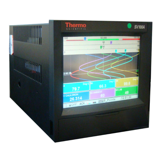
Chapter 1 Product Overview The Thermo Scientific SV100A/SV10AC SmartView 100mm paperless Introduction data acquisition system centers on providing engineers, operators, and technicians with an intuitive, scalable, and easy to maintain data acquisition platform. The instrument comes standard with both RS232 and RS485 serial interfaces that support the industry-standard Modbus protocol. -
Page 18: Specifications
Product Overview Specifications Specifications Results may vary under different operating conditions. Table 1-1. Operating Operating specifications Inputs 6, 12, or 18 isolated inputs Input types DC voltage: Linear, log, and square root programmable to 10 Vdc; full scale bipolar ranges include 50 mV, 100 mV, 200 mV, 1 V, 5 V, and 10 DC current: Linear, log, and square root, 4–20 mA, 10–50 mA, dry contact Thermocouple: J, K, T, E, R, S, B, C, Nicrosil Nisil, and Nickel/Nickel... - Page 19 Product Overview Specifications Recording specifications Internal memory 4 KB Battery-Backed Memory for System Parameters Storage media Secondary Compact Flash Card (1.0 GB or 2.0 GB) USB 2.0 Flash Device (File transfer only) Data saving method Data may be saved as instantaneous, average, maximum, or minimum values File types Data file (per screen basis), alarm/event file, and configuration file...
-
Page 20: Display
Product Overview Specifications Table 1-3. Display Display specifications Type 5.5-in. Color active matrix, TFT LCD Resolution 640 (H) x 480 (V) pixels Modes Maximum of eight user-defined screens Colors Maximum of 16 Display Update rate 125 msec. Data Update rate 15-bit: 250 msec. -
Page 21: Power
Product Overview Specifications Alarm functions Common alarm 1 rated at 100 mA at 250 Vdc/Vac Deadband/Fail-safe User selectable Power Table 1-6. Power specifications Requirements 90–132/180–264 Vac, 50/60 Hz Consumptions 40 VA maximum Power fail protection Programmed parameters stored in nonvolatile memory; clock retention in BBRAM approximately 12 months;... -
Page 22: Environmental
Software V & V (IEEE std. 7-4.3.2-1993), 10CFR 21, 10CFR 50 Appendix B, and IEEE 323-2003 (mild environment) Table 1-10. Factory Recommended Card Size Thermo Scientific P/N Compact Flash Cards 1.0 GB PA100259-08 (for use in both Primary & Secondary locations) 2.0 GB... -
Page 23: Chapter 2 Installation & Wiring
Due to battery life, we do not recommend storing the recorder for more than one year. If longer storage time is required, contact Thermo Scientific for additional storage information. -
Page 24: Panel Mounting
Installation & Wiring Installation marked, in close proximity to the recorder, and easily accessible to the operator. ▲ Panel Mounting Warning The recorder should be considered as permanently connected. Disconnection from the supply must be possible via a customer-supplied switch or circuit breaker. This disconnection device should be clearly marked, in close proximity to the recorder, and easily accessible to the operator. - Page 25 Installation & Wiring Installation 8. Install and tighten the remaining jackscrew into the keyhole located on the opposite side of the recorder case as described in steps 6–7. 9. Using a screwdriver, tighten both jackscrew leadscrews until the panel is held securely against the recorder bezel.
- Page 26 Installation & Wiring Installation Figure 2-2. Installation dimensions (2 of 2) SV100A/SV10AC User Guide Thermo Fisher Scientific...
- Page 27 Installation & Wiring Installation Figure 2-3. Panel cutout dimensions Thermo Fisher Scientific SV100A/SV10AC User Guide...
-
Page 28: Multiple Recorder Panel Mount
Installation & Wiring Installation Figure 2-4. For panel installation using jackscrews Note The jackscrews can be side mounted or top and bottom mounted.▲ Multiple Recorder Several recorders can be mounted together in a single panel. Refer to installation drawings for the minimum spacing requirements for multiple Panel Mount recorders. - Page 29 Installation & Wiring Installation 3. Refer to Figure 2–4. With the recorder held firmly in place against the relay rack, install one of the jackscrews by inserting the jackscrew nut into the keyhole located on the top of the instrument. 4.
-
Page 30: Wiring Procedures
Installation & Wiring Wiring Procedures Wiring Procedures The recorder operates on 90-132/180-264 Vac in a 50/60 Hz Power environment, enabling it to be used in most countries. The power supply is Requirements an auto-select unit which means there is no switch to select between Mains voltages of 90-132 Vac and 180-264 Vac, or operating frequency. - Page 31 Installation & Wiring Wiring Procedures Figure 2-6. Table 2-1. Country Ground* Line (HOT) Neutral (RET) Green Black White Green/yellow Brown Blue Refer to Figure 2–7 if your unit is connected to 240 Vac (180–264 Vac), 240 Vac Operating Power 50/60 Hz power. The wire color codes for USA and European Connections communities are shown in Table 2–1 in the previous section.
-
Page 32: Signal Input Wiring
Installation & Wiring Wiring Procedures Signal Input Wiring Warning Prevent the possibility of electrical shock or damage to the instrument. Disconnect power prior to making any connections. Use extreme caution when wiring signal input connections. ▲ Warning To prevent the possibility of electric shock, use extreme caution when wiring signal input connections. -
Page 33: General Wiring Instructions
Installation & Wiring Wiring Procedures Grounding: Signal cable shields or screens should be terminated at the General Wiring Instructions device end of the wire, not at the SV100A. Do not terminate shields at both ends, as this will set up a current loop in the shield. Read the procedures before connecting inputs to the terminals. -
Page 34: Rtd Inputs
Installation & Wiring Wiring Procedures RTD Inputs Use three wires having equal resistance to eliminate errors resulting from lead length variations. Use 14 AWG wire with terminal connectors for long lead runs and for 10-ohm copper RTDs. Refer to Figure 2–9 for connection information and to the RTD manufacturer specifications to determine color code connection information. -
Page 35: Linear Current Inputs
Installation & Wiring Wiring Procedures Linear current inputs consist of current inputs of 4–20 mA or 10–50 mA. Linear Current Inputs Connect current inputs as shown in Figure 2–11. Current inputs require that the 50- or 100-ohm shunt resistor be placed across the terminals. Figure 2-11. - Page 36 Installation & Wiring Wiring Procedures The optional two-wire transmitter power supply option provides an Two-Wire Transmitter Power isolated 24 Vdc current with a maximum output of 120 mA, which allows Supply you to power transmitters from the recorder rather than a separate power supply.
- Page 37 Installation & Wiring Wiring Procedures The recorder may be equipped with up to three optional digital Alarm Contact Output Connections input/output boards, each having six alarm relay contacts. The contact ratings are: 1 A at 120 Vac or 2.0 A at 24 Vdc resistive load ...
- Page 38 Installation & Wiring Wiring Procedures Figure 2-15. Alarm contact configuration Figure 2–16 shows connection detail for the alarm contacts. Figure 2-16. 2-16 SV100A/SV10AC User Guide Thermo Fisher Scientific...
-
Page 39: Event Marker Inputs
Installation & Wiring Wiring Procedures Six event marker inputs are available with the optional alarm relay/event Event Marker Inputs marker board. Event marker inputs must be dry contact/switch inputs. Connect event marker inputs as shown in Figure 2–17. Figure 2-17. The system alarm contact is provided directly below the RS485 System Alarm Contact connections and is configured as a fail-safe contact. -
Page 40: Serial Communication Port Connections
Installation & Wiring Wiring Procedures The recorder is equipped with one RS232 and one RS485 serial Serial Communication Port Connections communication port. The RS232 connection requires a standard DB9 female connector and cable. RS232 connections can support cable runs of up to 50 feet (16 m). - Page 41 Installation & Wiring Wiring Procedures Figure 2-21. Ethernet Port Connections The 10/100 Base-T Ethernet port uses a standard RJ45 connector. Wiring connections for the RJ45 connector are shown in Figure 2–22. Figure 2-22. Thermo Fisher Scientific SV100A/SV10AC User Guide 2-19...
-
Page 43: Operating The Instrument
Chapter 3 Operating the Instrument Operator Open the media door on the recorder to access several operator controls. These controls are shown in Figure 3–1 and described in the following Controls table. Figure 3-1. Table 3-1. Control Description Chassis Release A screw that holds the chassis firmly in the case. -
Page 44: Graphical Interface
Operating the Instrument Graphical Interface Control Description Allows you to insert/remove the media. Media slot accepts Media slot and Eject Compact Flash Cards. Media can only be removed via the media Button eject button located to the left of the medial slot, which is protected by the Warning Plate. - Page 45 Operating the Instrument Graphical Interface Figure 3-3. Button bar The following table describes the functions of each button shown in Figure 3-3. Table 3-1. Button # Function Menu/View button: Displays the main menu screen, enabling you to access the Program and Function menus or select a specific screen. Disk button: Pressing this button will display current parameters for the disk in the drive.
-
Page 47: The Program Menu
Chapter 4 The Program Menu General This section addresses each Program menu selection, except for Points, Screens/History, and Ports. Due to the detail involved in each, these selections are addressed in separate chapters. Access the Program menu by pressing Menu/View > Program Menu. Figure 4–1. -
Page 48: Date & Time
The Program Menu Date & Time b. Saver Intensity: Select the level of screen saver intensity. 3. Show Point Number: Select whether the digital blocks will display the point number. 4. Show Point Tag: Select whether the digital blocks will display the point tag. -
Page 49: Points
The Program Menu Points 3. Date: Enter the date. 4. Time: Enter the time in hh:mm:ss format. 5. Press Close when complete. Points Refer to Chapter 5. Measurement Figure 4–4. ADC Mode Figure 4–5. 1. Resolution: Selecting 14-bit resolution provides twice the normal scan speed with lower resolution. -
Page 50: Adc Constants
The Program Menu Measurement Table 4-1. Comparison of 14-bit & 15-bit resolutions Range 14-Bit Resolution (mV/bit) 15-Bit Resolution (mV/bit) 50 mV ~6 μV ~3 μV 100 mV ~12 μV ~6 μV 200 mV ~24 μV ~12 μV ~120 μV ~60 μV ~600 μV ~300 μV 10 V... -
Page 51: Factory
The Program Menu Ports Used by Thermo Scientific to perform a factory calibration. A factory Factory passcode is required. ADC Calibration Refer to the calibration section (Chapter 8). Ports Refer to Chapter 7. Media Control Figure 4–6. 1. Media Type: Select the physical media drive type for File I/O functions by pressing the applicable button. - Page 52 The Program Menu Media Control for the particular points’ stored data. The formula for determining the boundary setting follows: Boundary = Output Data Span Desired Accuracy. Example: Span of 0 to 20; accuracy of 0.1% Boundary = 20 0.001 = 0.02. The boundary can be set at 0.02, and any signal variation outside this range from the previous signal is stored to disk.
-
Page 53: System
The Program Menu System Fill Option Description Fail Contact Assign a standard contact output to activate when any problem is detected with storing data to the removable media. Alert Interval The alert window pops up on the display whenever a problem is detected with the removable media used for data storage. -
Page 54: Initialize
Press Cancel to escape this screen. Upgrade 1. Contact Thermo Scientific to receive the upgrade file. 2. Copy the file to the recorder PC card. 3. At the Program Menu, press System > Upgrade. -
Page 55: Screens/History
The Program Menu Screens/History Note Passcodes are case sensitive .▲ 1. Press the check box to set a passcode for the Program menu items, or press Next to move to the next screen and set a passcode for the Function menu items. 2. - Page 56 The Program Menu Digital I/O Standard Alarm Description Failsafe Contacts If fail-safe mode is not selected, alarm contact output relays are normally de-energized and will be energized when an alarm assigned to the contact occurs. Alternatively, if fail-safe mode is selected, the alarm contact output relays are normally energized and will be de-energized when an alarm assigned to the contact occurs.
- Page 57 The Program Menu Digital I/O 3. Digital Input screen: Figure 4–12. a. Switch Number: Enter the switch number you want to set up. b. Switch Function block: Each switch contact can be set up to actuate a recorder function. Press the button associated with the function you want to assign to the switch.
-
Page 58: File I/O
The Pr rogram Menu File I/O Switch nction Blank S creen ses the recorder r display to be se et at lowest pos sible inte ensity; useful dur ring training sess sions when ther e are long peri ods of inactivity y, switch action = = SPST. -
Page 59: Chapter 5 Point Programming
Chapter 5 Point Programming General Custom programming allows you to define functions and personalize features for performing specific applications and tasks. The programmed information is stored in nonvolatile memory. Programming is via menu- driven prompts. Recorder Functions The standard recorder is a 36-point recorder, of which a maximum of 18 points may be live inputs;... -
Page 60: Programming
Point Programming Programming Scaling: The outputs of the conditioning block are the values in the digital windows and are represented in common engineering units. The outputs of the conditioning block are also sent to a scale block where a chart scale is applied to each point. -
Page 61: Similar Programming Parameters
Point Programming Programming 2. If you are programming a range of points, touch the End Point box to enter the ending point number. Before continuing to the Type section, note that if you have two or more points with the same parameters, you can copy the data from one point to another rather than entering data again for each point. - Page 62 Point Programming Programming display a different color if the point goes into alarm. Press the Normal or Alarm color box and select the desired color. 4. Major, Submajor, and Minor Grids: You can enter a maximum of 15 major grids, submajor grids, and minor grids. Figure 5–3 shows how grids provide definition to the screen.
- Page 63 Point Programming Programming a. Assume you want to record the output from a pressure transducer which gives a 0–5 Vdc output signal, which coincides to a pressure of 0–3000 pounds per square inch (psi). The process being monitored typically runs at 2200 psi ±5%; this is the area of interest.
-
Page 64: Alarm Limits Screen
Point Programming Programming Band 3 Band 2 Band 1 Figure 5-6. 7. Decimal Fix: Select the desired number of digits to the right of the decimal point. Available decimal positions vary with point type. Alarm Limits Screen Figure 5–7. Alarm Limits screen The final screen for each programming session is the Alarm Limits screen. - Page 65 Point Programming Programming Rate: Set rate alarms (up to five) Certain parameters must be set when programming alarms: 1. Set point (for all alarms except None and Abnormal) 2. Contact number (for all alarms except None): Assign a contact number only if the optional GPIO (contact output) board is installed.
-
Page 66: Selecting A Point Type
Point Programming Programming Figure 5–8. 6. Abnormal value: Assign a numeric value to be used for point data in the event the point is flagged as abnormal (TCBO, overrange, invalid, etc.). The value is returned on a Modbus poll and is used for base point data in Equation and Conditional point types. - Page 67 Point Programming Programming automatically measured on the 1 V range) and 10–50 mA (assumes the use of a 100-ohm shunt resistor and is automatically measured on the 5 V range). If (a) current inputs are not predefined, (b) it is desired to use any selectable voltage range, and/or (c) it is desired to use a different shunt resistor for a current input, use Ohm’s Law to determine the appropriate low and high end input voltages:...
- Page 68 Point Programming Programming 3. Parameters screen: Figure 5–10. Linear type point programming: Parameters screen a. Input Low and High Scales: The input scale set must remain within the input point type range for the point. For example, if you select a point type of 5 V (±5 V range) and your input signal is 2–5 V, you can set the input scale for 2–5 V.
- Page 69 Point Programming Programming Figure 5–11. d. Current: Currents must be enabled to measure a passive resistance to the recorder. The recorder uses a precision current source to measure resistance. If a resistance, other than an RTD, is entered into an input, this function must be enabled. Refer to the following example.
-
Page 70: Thermocouple
Point Programming Programming This type measures temperature. Thermocouple 1. Type screen: Figure 5–12. Thermocouple type point programming: Type screen Select one of the available types: J, K, T, E, R, S, B, C, M (NI-NI MOLY), or N (NICROSIL-NISIL). Press Next to continue. 2. - Page 71 Point Programming Programming c. Normal and Alarm Colors: Refer to the Similar Programming Parameters section for instructions. d. Display Block: Refer to the Similar Programming Parameters section for instructions. Note that the only options available for Decimal Fix are 0 and 1. Press Next. 3.
-
Page 72: Rtd
Point Programming Programming 4. Press Next. 5. Alarm limits screen: Refer to the Similar Programming Parameters section for instructions. 6. Press Apply. RTD type points are used to measure temperature. 1. Type screen: Select the RTD type and press Next. Figure 5–15. -
Page 73: Log Linear
Point Programming Programming Note Kelvin is not supported in this release; however, an Equation type point may be used to convert temperatures in Celsius or Fahrenheit to Kelvin. ▲ c. Colors Block: Refer to the Similar Programming Parameters section for instructions. d. -
Page 74: Ind Sqrt
Point Programming Programming b. Display Block: Refer to the Similar Programming Parameters section for instructions. Note the following differences: Major/Submajor/Minor Grids: Not programmable. Grids are fixed based on the number of log scale decades. Decimal Fix: Not programmable. Log points displayed as base 10 exponentials. -
Page 75: Dry Contact
Point Programming Programming 3. Parameters screen: Figure 5–18. Ind Sqrt type point programming: Parameters screen a. Input Scales block: Refer to step 3a in the Linear type point programming section. b. Output Scales block: Refer to step 3b in the Linear type point programming section. - Page 76 Point Programming Programming Figure 5–19. Dry Contact type point programming: Display Scale screen a. Text and Colors blocks: Refer to the Similar Programming Parameters section for instructions. b. Display block: Refer to the Similar Programming Parameters section for instructions. Note that Decimal Fix is not programmable.
-
Page 77: Calculated
Point Programming Programming Calculations are performed on the instantaneous value of one or more Calculated points. The calculations are performed after each scan of all measured inputs. High Peak, Low Peak, Time Average: High peak calculated type points track the highest data of a given point. This data is stored until some form of reset occurs. - Page 78 Point Programming Programming Figure 5–22. Hi Peak Calculated type point programming: Parameters screen a. Base Point: High peak, low peak, and time average calculations must be performed on another point. This point is referred to as the base point. To establish the base point, press the Base Point input box and type in the base point number.
- Page 79 Point Programming Programming once a month at the start time set and on the day of the month you set. For example, programming the reset for a start time of 12:00 on the twentieth day of the month causes the point to reset every month on the twentieth at 12:00 that day.
- Page 80 Point Programming Programming Table 5-1. Example of the Auto Reset Function Time Actions 8:00 Operator programs the Auto Reset Function * Start Time set to 9:30 am * Timed Interval set to 4.5 hours 9:30 Auto Reset Function begins collecting and analyzing the point data 14:00 Recorder saves High Peak, Low Peak or Time Average point value found during the first 4.5 hour interval to the Alarm Event Summary Screen and resets the function to start collecting the next...
- Page 81 Point Programming Programming c. Press Next. d. Alarm Limits screen: Refer to the Similar Programming Parameters section for instructions. e. Press Apply. High-Low Difference: This calculated type point takes the difference between the lowest and highest values in a range of points. The final data for a high-low difference point type is derived by subtracting the lowest point data in the range of points from the highest data.
- Page 82 Point Programming Programming 3. Parameters screen: Figure 5–24. High-Low Difference Calculated type point programming; Parameters screen a. First Point and Last Point: The high-low difference point is the average of the first and last points. For example, within the range of points assigned to the Hi-Lo difference point type, if the highest point data value is 100 and the lowest is 90, the high-low difference data will be 10.
- Page 83 Point Programming Programming Figure 5–25. Totalize Calculated type point programming: Type screen 2. Display Scale screen: Refer to the Similar Programming Parameters section for instructions. 3. Parameters screen: Figure 5–26. Totalize Calculated type point programming: Parameters screen a. Base Point: Totalize calculations must be performed on a base point.
-
Page 84: Moving Average Function: Description
Point Programming Programming 4. Alarm Limits screen: Refer to the Similar Programming Parameters section for instructions. 5. Press Apply. Moving Average: A moving average point calculates the continuous average of the measured or processed value of a selected point. A description of the moving average function and an application follows. - Page 85 Point Programming Programming 1. Type screen: Select Moving Average > Next. Figure 5–27. Moving Average Calculated type point programming: Type screen 2. Display Scale screen: Refer to the Similar Programming Parameters section for instructions. 3. Parameters screen: Figure 5–28. Moving Average Calculated type point programming: Parameters screen a.
- Page 86 Point Programming Programming 5. Press Apply. Note A Moving Average will be invalid until the first average period has elapsed. Furthermore, if the base point becomes invalid for any reason during an average period, a full average period must elapse before the Moving Average becomes valid again.
- Page 87 Point Programming Programming 2. Display Scale screen: Figure 5–30. Gated Timer Calculated type point programming: Display Scale screen a. Text and Colors blocks: Refer to the Similar Programming Parameters section for instructions. b. Display block: Refer to the Similar Programming Parameters section for instructions.
- Page 88 Point Programming Programming 4. Alarm Limits screen: Refer to the Similar Programming Parameters section for instructions. 5. Press Apply Sterilize: The sterilize type point allows you to set a reference temperature and a Z constant to calculate the value of a point. The calculation used follows: + (1/60) * 10 ^ ((BP –...
- Page 89 Point Programming Programming Figure 5–33. Sterilize Calculated type point programming: Parameters screen a. Base Point: The base point is the actual temperature of the process and is compared to the reference temperature. b. Z Constant: To establish a constant other than the default constant (10°C), press the input box and type in the number.
- Page 90 Point Programming Programming point is reset and begins again. If the sterilization point is bypassed and reactivated, the point resets and begins again. iv. Target Temperature: Enter the minimum allowable temperature for the process. v. Deadband: This is the allowable range above and below the target temperature.
- Page 91 Point Programming Programming 2. Display Scale screen: Figure 5–35. Equation Calculated type point programming: Display Scale screen (linear scale) a. Tag: You can assign a tag with up to 20 characters to each programmed point. b. Units: An alphanumeric engineering units message with a maximum of 20 characters may be assigned for voltage and current inputs.
- Page 92 Point Programming Programming Figure 55–36. Equation Calculated type point programming: Display Scale screen (log scale) 3. Parameters screen: Figure 5–37. Equation Calculated type point programming: Parameters screen Create or modify an equation by pressing the Edit button and using the equation editor that appears (Figure 5–38). Press Accept when complete.
-
Page 93: Conditional
Point Programming Programming The following describes the operators and functions available through the equation editor. Table 5-2. Operator Function Operator Function Constant Select a constant (K01– Point Select a point (1–36). K24). Event Select an event (1–18). Back Move back through the equation. - Page 94 Point Programming Programming 1. Display Scale screen: Figure 5–39. Conditional Calculated type point programming: Display Scale screen a. Text and Colors blocks: Refer to the Similar Programming Parameters section. b. Display Block: Refer to the Similar Programming Parameters section. Note that the only option available for Decimal Fix is c.
- Page 95 Point Programming Programming Figure 5–41. Conditional Calculation type point programming: Equation entry A total of 40 operators and operands may be used in an equation. If an equation is not constructed properly, an Error: Invalid Data dialog box displaying Illegal Equation appears. The following describes the operators and functions available through the equation editor.
-
Page 96: External
Point Programming Programming 4. Alarm Limits screen: Refer to the Similar Programming Parameters section for instructions. Note the following differences: a. Type: Available alarms include None, Abnormal, True, False. b. Alarm Deadband: Not available. 5. Press Apply External External type points use data sent via the RS232, RS485, or Ethernet ports to the recorder for trending or other uses. - Page 97 Point Programming Programming Programming Parameters. Decimal Fix is also not programmable, as log point are displayed as base 10 exponentials. e. Press Next. Figure 5–43. External type point programming: Display Scale screen (log scale type) 2. Parameters screen: Figure 5–44. External type point programming: Parameters screen a.
- Page 98 Point Programming Programming 3. Alarm Limits screen: Refer to the Similar Programming Parameters section for instructions. 4. Press Apply. 5-40 SV100A/SV10AC User Guide Thermo Fisher Scientific...
-
Page 99: Chapter 6 Screen Types
Chapter 6 Screen Types Display Features Following are descriptions of display features and which displays use them. Figure 6–1. Table 6-1. Display Feature Description Digital blocks May be displayed with the trend displays. Press Show to turn on and off. Displays current scaled data for the points. Grids Are both horizontal and vertical. -
Page 100: Setup
Screen Types Setup Screens are selected by pressing the Menu/View button on the button bar. Setup To set up a screen: 1. Go to the Program menu screen by pressing the Menu/View button on the button bar. 2. Select Screens/History and the screen in Figure 6–2 opens. Figure 6–2. -
Page 101: Horizontal & Vertical Trend Screens
Screen Types Horizontal & Vertical Trend Screens These screens emulate paper-type chart recorders with pens; they can show Horizontal & up to six programmed points. Figure 6–4 displays a typical horizontal trend Vertical Trend (H_Trend) and vertical trend (V_Trend) screens, respectively. Instructions on setting up a trend screen follow. - Page 102 Compact Flash card to store data, refer to the following for a list of recommended cards. Table 6-1. Card Size Thermo Scientific P/N 1.0 GB PA100259-08 (for use in both Primary & Secondary locations) 2.0 GB PA100259-09 (for Secondary location only)
- Page 103 Screen Types Horizontal & Vertical Trend Screens Figure 6–7. Horizontal trend: History definition a. History: Enable or disable (On/Off) the history function. b. Background Review Color: Assign a color to the history review background that enables you to differentiate between history and normal trend screens.
- Page 104 Screen Types Horizontal & Vertical Trend Screens Interval Trigger: Figure 6–9. Interval trigger setup Sync Time – Allows you to synchronize the times that actual sample data are stored. Normal Rate – Specifies the frequency at which the recorder stores data from all points within the designated point group.
- Page 105 Screen Types Horizontal & Vertical Trend Screens Figure 6–11. Stop Mode – Collect Count Samples Switch Trigger: If you select Switch trigger, press the input box. Enter the switch you want to designate and press OK. This trigger type also opens the Stop Mode section. Refer to Figure 6–12.
-
Page 106: Horizontal & Vertical Bargraph Screens
Screen Types Horizontal & Vertical Bargraph Screens Instructions for programming the Horizongal (H_Bargraph) and the Horizontal & Vertical bargraph (V_Bargraph) screens are identical. Vertical Bargraph Screens Figure 6–14. Typical Horizontal Bargraph screen 1. Screen definition: Figure 6–15. Horizontal bargraph: Screen definition a. -
Page 107: Digital Screen
Screen Types Digital Screen Digital blocks are shown for a maximum of six programmed points. The Digital Screen large numbers in the center of the window are the real-time point value, and above the point value is the point tag. Below the point value is the selected engineering unit. -
Page 108: Overview Screen
Screen Types Overview Screen Overview Screen This screen displays up to 18 points in a digital block format, allowing you to quickly survey a range of points in the recorder. If more than 18 points are programmed, touch the Next button on the button bar to display the next page of points. - Page 109 Screen Types Alarms/Events Summary Screen Point resets: Points that may be reset, such as totalizers, are displayed with the actual value at the time of reset. Some point types such as HI PEAK may have two entries. The first entry is the date and time that the high peak occurred, with the peak value.
-
Page 110: Reviewing Recorder Memory
Screen Types Reviewing Recorder Memory You can review data stored in the recorder’s memory from any display with Reviewing the Review button showing on the button bar (Figure 3-3). During review, Recorder you may turn digital blocks on or off. Figure 6–22 depicts a horizontal trend display with Review turned on and describes the functions on the Memory vertical button bar. -
Page 111: Chapter 7 Setting Up Communications
Chapter 7 Setting up Communications This section addresses the Ports menu item. Figure 7-1. Ports menu Follow these steps to access the serial communication programming Serial screens: Communications 1. Access the Program menu, and press Ports. 2. Press Serial. 3. Press Modbus ID and enter the recorder’s (Modbus slave) ID number. This number can be from 1 to 255 for use in your communications system. -
Page 112: Rs232 Serial Port
Setting up Communications Serial Communications Figure 7-2. Serial ports menu The RS232 interface allows a recorder to communicate with a computer at RS232 Serial Port a distance of up to 50 feet (16 m). The RS232 port may be used for distances in excess of 50 feet as long as special low capacitance cables are utilized. -
Page 113: Rs485 Serial Port
Setting up Communications Parallel Printer Port The RS485 interface allows a recorder to communicate with a computer up RS485 Serial Port to a maximum of 4000 feet (1300 m). The RS485 interface supports up to 31 recorders linked to a single computer. Each recorder is identified by a unique unit address (Modbus ID). - Page 114 Setting up Communications Ethernet Port Acting as an FTP client: The recorder also supports remote FTP servers over the LAN by acting as an FTP client. In this case, you can configure the instrument to automatically send all recorded data (stored as day-files on the local recorder media) periodically to the host FTP server.
- Page 115 Setting up Communications Ethernet Port c. Default Gateway: This is the IP address that is used when communicating with other devices on a different network. The address is a 32-bit value normally expressed with four values (0 to 255) separated by a period. The default setting is 0.0.0.0. Set this value according to the system or the network to which the recorder belongs.
- Page 116 Setting up Communications Ethernet Port • Select whether you want to set up the primary or secondary server. • FTP Server: The FTP server you are connecting to may have a server name. Enter the name. It must exactly match the server name/IP address for the FTP server.
-
Page 117: Modbus Rtu & Ascii Functions
The original Modbus specification has no mention of floating point numbers. Therefore, several methods of transferring floating point numbers have emerged. Thermo Scientific supports two of these methods. One is compatible with the Modicon 984 PLC and the other is referred to as the Daniel’s Extension. -
Page 118: Modicon 984 Plc Compatible Format
Setting up Communications Modbus RTU & ASCII Functions Sign Bit Exponent Mantissa (+127 biased) (extra implied 1 bit) 1 bit 8 bits 23 bits SEEEEEEE | EMMMMMMM | MMMMMMMM | MMMMMMMM Byte 0 | Byte 1 | Byte 2 | Byte 3 High Word Low Word This is a 2 x 16 format (2 consecutive register addresses for one floating... - Page 119 Setting up Communications Modbus RTU & ASCII Functions Table 7-2. Coil Registers 0XXX Data Type: Bit Functions: 1, 15 Read/Write Coil # Function and State Coil # Function and State 0001 ACKNOWLEDGE ALARMS 0077 RESET POINT 2 0002 ALARM CHECKS ENABLE/DISABLE ·...
- Page 120 Setting up Communications Modbus RTU & ASCII Functions Table 7-4. 16-Bit Input Registers 2XXX Data Type: 16-Bit Functions: 4 Read Register # Function and State Register # Function and State 3000 POINT 0 STATUS ∙ 3001 POINT 1 STATUS ∙ 3002 POINT 2 STATUS 3035...
- Page 121 Setting up Communications Modbus RTU & ASCII Functions Table 7-7. 32-Bit Input Registers 7XXX Data Type: 32-Bit Functions: 4 Read Register # Function and State Register # Function and State 7001 POINT 1 DATA 7039 PONIT 2 DISPLAY SCALE LOW END 7002 POINT 2 DATA 7040...
-
Page 123: Chapter 8 Calibration
Chapter 8 Calibration Caution Do not attempt to perform calibration until you are fully prepared to do so. Following incorrect procedures can destroy instrument calibration. Read this entire chapter before attempting to calibrate the unit. ▲ Note Allow the recorder to warm up and stabilize (approximately 15 minutes at room temperature) prior to performing calibration. -
Page 124: Procedure
Calibration Scale Calibration Procedure 1. Connect the precision voltage source to the positive (+) and negative (-) calibration inputs. Verify correct polarity. Figure 8-1. Connection detail 2. Turn on the voltage source and allow it to stabilize. 3. Press Program > Measurement. 4. -
Page 125: Current Calibration
Calibration Current Calibration Note The remaining steps use the 50 mV range; however, these steps are the same regardless of the range you select. ▲ 7. A known good -50 and +50 mV (or the range you selected) must be supplied to the recorder’s calibration input. -
Page 126: Restoring Calibration Constant Defaults
Calibration Restoring Calibration Constant Defaults Note The mA reading may not show the correct value until current range calibration is completed and you return to the calibration screen. ▲ Restoring Three constants are calculated and saved in nonvolatile memory for each voltage range, and one constant is calculated and saved in nonvolatile Calibration memory for the current source. -
Page 127: Chapter 9 The Function Menu
Chapter 9 The Function Menu The Function menu enables you to access routine functions quickly. Figure 9-1. Activate Point Access this screen to activate a bypassed point or range of points. Enter the point or range of points to activate. Figure 9-2. -
Page 128: Reset Point
The Function Menu Reset Point Figure 9-3. Reset Point Enter the point or range of points to reset. Figure 9-4. The alarm check function causes point data to be compared to the alarm Alarm Check set point. Figure 9-5. USB Media You can move files from the instrument without disturbing the recording by transferring them to an inserted USB flash memory module. - Page 129 The Function Menu USB Media Figure 9-6. Touch one of the day folders (Figure 9–6) and the usb transfer options window open (Figure 9-7) Figure 9-7. Note Files must be Encrypted when using the Pronto Software Version 5.71 or newer. ▲ Touch the Transfer button to display the progress of the transfer (Figure 9–...
-
Page 130: Recording
The Function Menu Recording Figure 9-8. Figure 9-9. Recording The recording function causes the recorder to send the point data to the media. Figure 9-10. SV100A/SV10AC User Guide Thermo Fisher Scientific... -
Page 131: Chart Speed
The Function Menu Chart Speed Chart Speed This menu item allows you to globally change the chart speed. Figure 9-11. Before you set a message to print on the trend screens and to the Trend Message event/alarm log, you must first program the messages, as detailed in Digital I/O in Chapter 4. -
Page 133: Chapter 10 Maintenance & Troubleshooting
Chapter 10 Maintenance & Troubleshooting Warning Hazardous potentials may exist on signal input terminals which are floating, with respect to case ground. These hazardous potentials may be on the rear terminal panel of your instrument. Any voltage potential at the signal source will exist at the instrument’s respective signal input terminal, for example, power generator winding temperature monitoring thermocouples. -
Page 134: General Troubleshooting
Is power supply board Reseat board. properly seated? Does disk drive lamp Power supply board and fuse are OK. illuminate periodically? Contact Thermo Scientific. Power supply board is Check and/or replace fuse on power properly seated and disk drive supply board. -
Page 135: Diagnostics
Check filter process. Is input signal’s amplitude Verify recorder can follow input. fluctuating rapidly? Recorder is in Live mode, Contact Thermo Scientific. digital filter constant is 0, and input signal’s amplitude is not fluctuating rapidly. No data on disk Is proper media type selected? Select proper media type (Chapter 4). -
Page 136: Watchdog Test
Maintenance & Troubleshooting Figure 10-1. The Watchdog Timer test function tests the watchdog timer circuit which Watchdog Test monitors the software execution on the CPU. Initiating this test removes the tickler signal from the watchdog timer, allowing the timer to time out and reset the unit. -
Page 137: Ambient Temps
Maintenance & Troubleshooting Ambient Temps This function tests the ambient temperature circuits on the rear terminal panel. A screen displays the temperature reading for the upper and lower sensors. If these temperatures are not accurate, the temperature sensor circuits are malfunctioning. Refer to Figure 10–2. Figure 10-2. -
Page 138: Usb Test
Maintenance & Troubleshooting USB Test With a USB module installed, touch the USB Test button. A good/compatible module will produce the screen shown in Figure 10–4. This test also enables you to verify that the USB port is functioning properly. Figure 10-4. -
Page 139: Removing The Chassis
Maintenance & Troubleshooting Removing the Chassis Warning To prevent the possibility of electrical shock, disconnect power to the recorder. ▲ 1. Open the media door and turn the chassis release screw counterclockwise. 2. When the screw is loose, grasp the bezel on each side at the bottom, and pull the chassis straight out of the case. -
Page 140: Display/Touchscreen Assembly
Touchscreen, CPU card, or Compact Flash assembly (mounted on the bottom of the Display Touchscreen Assembly) the SV100A unit should be submitted to Thermo Scientific for repair. Power Supply Fuse Note Replace the fuse with a fuse of the same type and rating. Refer to Appendix C for part number and rating. -
Page 141: Cpu Dip Switch Settings
CPU DIP Switch The following table includes the switch control operations and normal settings for the instrument. Settings Caution Do not change the switch settings from Normal unless instructed by Thermo Scientific. ▲ Table 10-3. Switch Control Operation Normal Setting... -
Page 142: Service
The local representative is the first contact for support and is well equipped to answer questions and provide application assistance. Your representative has access to product information and current software revisions. You can also contact Thermo Scientific directly. Process Instruments 1410 Gillingham Lane... -
Page 143: Warranty
Shipment of repaired or replacement goods from Thermo Scientific plant shall be F.O.B. Thermo Scientific plant. A quotation of proposed work will be sent to the customer. Thermo Scientific shall be liable only to replace or repair, at its option, free of charge, products which are found by... -
Page 145: Chapter 11 Documentation
Chapter 11 Documentation This chapter contains the documentation required for troubleshooting, maintenance, and service. Note Information presented in this chapter has been regenerated from original drawings. Every effort is made to maintain document accuracy. However, in order to enhance legibility, the documents may have been restructured, and some information may have been intentionally excluded. - Page 146 Documentation Figure 11-1. DM100164: Installation dimensions (sheet 1 of 2) 11-2 SV100/SV10C User Guide Thermo Fisher Scientific...
- Page 147 Documentation Figure 11-2. DM100164: Installation dimensions (sheet 2 of 2) Thermo Fisher Scientific SV100/SV10C User Guide 11-3...
- Page 148 Documentation Figure 11-3. DM100165: Rear terminal assignment (sheet 1 of 4) 11-4 SV100/SV10C User Guide Thermo Fisher Scientific...
- Page 149 Documentation Figure 11-4. DM100165: Rear terminal assignment (sheet 2 of 4) Thermo Fisher Scientific SV100/SV10C User Guide 11-5...
- Page 150 Documentation Figure 11-5. DM100165: Rear terminal assignment (sheet 3 of 4) 11-6 SV100/SV10C User Guide Thermo Fisher Scientific...
- Page 151 Documentation Figure 11-6. DM100165: Rear terminal assignment (sheet 4 of 4) Thermo Fisher Scientific SV100/SV10C User Guide 11-7...
-
Page 153: Appendix A Return Authorization
Appendix A Return Authorization All equipment and/or parts to be returned to Thermo Scientific for repair or credit must have a Return Material Authorization (RMA). This RMA is issued by the service department. When calling for an RMA, please provide your purchase order number and an explanation of why equipment and/or parts are being returned. - Page 154 4. Ship unit with all shipping screws and other shipping retaining devices in place. 5. Shipping boxes are available from Thermo Scientific for a small charge. Please consult service department for pricing. SV100/SV10C User Guide...
-
Page 155: Appendix B Recommended Spare Parts
Appendix B Recommended Spare Parts Commercial Grade The following spare parts are recommended for installations that require minimum downtime. Installations with 10 or more recorders should have Recorders at least 2 sets of recommended spare parts. (*) Indicates spare parts that are recommended for normal service support. Table B-1. -
Page 156: Controlled Program Recorders
Recommended Spare Parts Controlled Program The following spare parts are recommended for installations that require minimum downtime. Installations with 10 or more recorders should have Recorders at least two sets of recommended spare parts. (*) Indicates spare parts that are recommended for normal service support. Table B-2. -
Page 157: Appendix C Point Programming Forms
Appendix C Point Programming Forms Use the forms on the following pages to record data as you connect inputs. Make copies as needed. Thermo Fisher Scientific SV100/SV10C User Guide... - Page 158 Point Programming Forms Unit Tag: Point #: Page Linear Type Point Type: 50 mV 100 mV 200 mV 10 V 4–20 mA 10–50 mA Display Scale Point tag: Eng. units: Normal color: Alarm color: Major grid: Submajor grid: Minor grid: Low scale: High scale: Bands:...
- Page 159 Point Programming Forms Unit Tag: Point #: Page Thermocouple Type Point Type: Display Scale Point tag: Degrees: Normal color: Alarm color: Major grid: Submajor grid: Minor grid: Low scale: High scale: Bands: Enabled Disabled Band Low scale High scale Color Decimal fix: Parameters Filter:...
- Page 160 Point Programming Forms Unit Tag: Point #: Page RTD Type Point Type: 10 cu 100 pt 385 100 pt 392 200 pt 385 200 pt 392 500 pt 385 120 ni Display Scale Point tag: Degrees: Normal color: Alarm color: Major grid: Submajor grid: Minor grid:...
- Page 161 Point Programming Forms Unit Tag: Point #: Page Log Linear Type Point Type: 50 mV 100 mV 200 mV 10 V 4–20 mA 10–50 mA Display Scale Point tag: Eng. units: Normal color: Alarm color: Major grid: Not programmable Submajor grid: Not programmable Minor grid: Not programmable Low scale: High scale:...
- Page 162 Point Programming Forms Unit Tag: Point #: Page Ind Sqrt Type Point Type: 50 mV 100 mV 200 mV 10 V 4–20 mA 10–50 mA Display Scale Point tag: Eng. units: Normal color: Alarm color: Major grid: Submajor grid: Minor grid: Low scale: High scale: Bands:...
- Page 163 Point Programming Forms Unit Tag: Point #: Page Dry Contact Type Point Display Scale Point tag: Eng. units: Normal color: Alarm color: Major grid: Submajor grid: Minor grid: Low scale: High scale: Bands: Enabled Disabled Band Low scale High scale Color Decimal fix: Not programmable Alarms...
- Page 164 Point Programming Forms Unit Tag: Point #: Page Calculated Type Point: High Peak, Low Peak, Time Average Display Scale Point tag: Eng. units: Normal color: Alarm color: Major grid: Submajor grid: Minor grid: Low scale: High scale: Bands: Enabled Disabled Band Low scale High scale...
- Page 165 Point Programming Forms Unit Tag: Point #: Page Calculated Type Point: High-Low Difference Display Scale Point tag: Eng. units: Normal color: Alarm color: Major grid: Submajor grid: Minor grid: Low scale: High scale: Bands: Enabled Disabled Band Low scale High scale Color Decimal fix: Parameters...
- Page 166 Point Programming Forms Unit Tag: Point #: Page Calculated Type Point: Totalize Display Scale Point tag: Eng. units: Normal color: Alarm color: Major grid: Submajor grid: Minor grid: Low scale: High scale: Bands: Enabled Disabled Band Low scale High scale Color Decimal fix: Parameters...
- Page 167 Point Programming Forms Unit Tag: Point #: Page Calculated Type Point: Moving Average Display Scale Point tag: Eng. units: Normal color: Alarm color: Major grid: Submajor grid: Minor grid: Low scale: High scale: Bands: Enabled Disabled Band Low scale High scale Color Decimal fix: Parameters...
- Page 168 Point Programming Forms Unit Tag: Point #: Page Calculated Type Point: Gated Timer Display Scale Point tag: Eng. units: Normal color: Alarm color: Major grid: Submajor grid: Minor grid: Low scale: High scale: Bands: Enabled Disabled Band Low scale High scale Color Decimal fix: Not programmable Parameters...
- Page 169 Point Programming Forms Unit Tag: Point #: Page Calculated Type Point: Sterilize Display Scale Point tag: Eng. units: Normal color: Alarm color: Major grid: Submajor grid: Minor grid: Low scale: High scale: Bands: Enabled Disabled Band Low scale High scale Color Decimal fix: Parameters...
- Page 170 Point Programming Forms Unit Tag: Point #: Page Calculated Type Point: Equation Equation: Display Scale Point tag: Eng. units: Normal color: Alarm color: Scale type: Linear Major grid (Linear scale only): Submajor grid (Linear scale only): Minor grid (Linear scale only): Low scale: High scale: Bands:...
- Page 171 Point Programming Forms Unit Tag: Point #: Page Conditional Type Point Equation: Display Scale Point tag: Eng. units: Normal color: Alarm color: Major grid: Submajor grid: Minor grid: Low scale: High scale: Bands: Enabled Disabled Band Low scale High scale Color Decimal fix: Not programmable Alarms...
- Page 172 Point Programming Forms Unit Tag: Point #: Page External Type Point Display Scale Point tag: Eng. units: Normal color: Alarm color: Scale type: Linear Major grid (Linear scale only): Submajor grid (Linear scale only): Minor grid (Linear scale only): Low scale: High scale: Bands: Enabled...
-
Page 173: Cell Explanations
Point Programming Forms Cell Abnormal Value: This numeric value is used as base point data by certain point types (equations, conditionals) in the event that the base point is in Explanations an abnormal state (invalid, TCBO, overrange, etc.). Auto, Reset: Assign as on or off; if on, assign time/day for daily, weekly, or monthly Base Point: Assign a point as the base point. - Page 174 Point Programming Forms Interval, Reset: Enter the time, weekday, or day of month for a reset interval. Last Base Point: Assign a point as the last base point in a series. Low Flow Cutoff: Assign a low value to stop totalization. Offset: Assign thermocouple offset correction value.
- Page 175 Point Programming Forms Units: Enter the five-character (maximum) engineering unit description assigned to current and voltage inputs and calculated points; for thermocouples and RTDs, select either degrees C or F. Z Constant: Enter the constant value for sterilization. Thermo Fisher Scientific SV100/SV10C User Guide C-19...
-
Page 177: Appendix D Unit Programming Forms
Appendix D Unit Programming Forms Use the forms on the following pages to record data as you program the unit. Make copies as needed. Thermo Fisher Scientific SV100/SV10C User Guide... - Page 178 Unit Programming Forms Unit Tag: Page Display Control Normal intensity: Medium High Screen saver: No Wait (s): Saver intensity: Medium Show point #: Show point tag: Auto speed: Alarm blink: Clear unit at startup: Chart speed unit: inch/hour mm/hour Date & Time Daylight Saving Time: Display format: American...
- Page 179 Unit Programming Forms Unit Tag: Page Ports, cont. Ethernet IP address: Subnet mask: Gateway: FTP config client user name: FTP config client password: Float format: 1x32 2x16 Web port: FTP Server Login Auto transfer: Hour: FTP Connection: Primary FTP Connection: Secondary FTP server: FTP server: Port:...
- Page 180 Unit Programming Forms Unit Tag: Page System Unit ID: Language: English Spanish Program passcode: Function passcode: Display control Media control Activate point Recording on/off Date & time System Bypass point Chart speed hi/low Points Screens/history Reset point Trend message Measurement Digital I/O Alarm checks Display previous...
- Page 181 Unit Programming Forms Unit Tag: Page Digital I/O Standard alarm contacts: Open on alarm clear Open on acknowledge Failsafe contacts Reflash contacts Common alarm contacts: Link to media status Link to unit fault Link to point alarms Open on alarm clear Open on acknowledge Switch: 1 Function:...
- Page 182 Unit Programming Forms Unit Tag: Page Digital I/O, cont. Switch: 9 Function: None Event ACK Alarm Copy Screen Chart Speed Alarm check Recording Freeze Unit Clear Unit Blank Screen Open message: Close message: Switch: 10 Function: None Event ACK Alarm Copy Screen Chart Speed Alarm check...
- Page 183 Unit Programming Forms Function Menu Recording: Chart speed: High Alarm check: Thermo Fisher Scientific SV100/SV10C User Guide...
- Page 184 Thermo Fisher Scientific 81 Wyman Street P.O. Box 9046 Waltham, Massachusetts 02454-9046 United States www.thermofisher.com...
Need help?
Do you have a question about the SmartView SV100A and is the answer not in the manual?
Questions and answers