
Subscribe to Our Youtube Channel
Related Manuals for Thermo Scientific STF55433


Summary of Contents for Thermo Scientific STF55433
- Page 1 Thermo Scientific Lindberg/Blue M 1500°C General-Purpose Tube Furnaces Models: STF55433 Installation and Operating Manual 305435H03 • Revision B • November 2020...
- Page 2 © 2020 Thermo Fisher Scientific Inc. All rights reserved. Thermo Fisher Scientific Inc. provides this document to its customers with a product purchase to use in the product operation. This document is copyright protected and any reproduction of the whole or any part of this document is strictly prohibited, except with the written authorization of Thermo Fisher Scientific Inc.
-
Page 3: Table Of Contents
Table of Contents Table of Contents Chapter 1 Safety Precautions ..............1-5 Explanation of Symbols . - Page 4 Table of Contents The Operator Buttons ............7-47 Shortcut Key Presses .
- Page 5 Figure 11 Heating Element Replacement ....................10-84 Figure 12 Control Module Replacement ....................10-84 Figure 13 Control ..........................10-85 Figure 14 Wiring Diagram STF55433 series ................... 12-91 Figure 15 Wiring Diagram STF55433P Series ..................12-92 1500°C Tube Furnace 305435H03 | 3...
- Page 6 Figures 305435H03 1500°C Tube Furnace...
-
Page 7: Safety Precautions
Safety Precautions | Chapter 1 Safety Precautions Explanation of Symbols This symbol when used alone indicates important operating instructions which reduce the risk of injury or poor performance of the unit. DANGER : Indicates a hazardous situation which, if not avoided, will result in death or serious injuries. - Page 8 | Safety Precautions Chapter 1 This symbol indicates power is ON. This symbol indicates power is OFF. This symbol indicates Alternating current. This symbol indicates Earth ground power. This symbol indicates Protective conductor terminal. 305435H03 1500°C Tube Furnace...
-
Page 9: Safety Considerations
Safety Precautions | Chapter 1 Safety Considerations DANGER : Use this product only in the way described in the product literature and in this manual. Before using it, verify that this product is suitable for its intended use. If the equipment is used in a manner not specified by the manufacturer, the protection provided by the equipment may be impaired. - Page 10 | Safety Precautions Chapter 1 WARNING : This product can expose you to chemicals including arsenic, which is known to the state of California to cause cancer. For more information go to www.P65Warnings.ca.gov. WARNING : Before maintaining this equipment, read the applicable SDS (Safety Data Sheets).
-
Page 11: Standards And Directives
Safety Precautions | Chapter 1 Standards and Directives The tube furnaces complies with the following standards and guidelines: European Union The European voltage models of this product meet all the applicable requirements of the European Directives and therefore display the CE Marking. - Page 12 | Safety Precautions Chapter 1 South Korean EMC Statement 사용자안내문이기기는업무용환경에서사용할목적으로적합성평가를받 은기기로 서가정용환경에서사용하는경우전파간섭의우려가있습니다 . EMC Registration is done on this equipment for business use only. It may cause interference when the product would be used in home. Evaluation of Chemicals - Regulations and Directives Proposition 65 - California WARNING : Cancer and Reproductive Harm - www.P65Warnings.ca.gov...
- Page 13 Safety Precautions | Chapter 1 RoHS – China This product complies with the requirements of the legislative act Administration on the Control of Pollution Caused by Electronic Information Products (ACPEIP). The following label of conformance, may be found on the product: 1500°C Tube Furnace 305435H03 | 1-11...
- Page 14 | Safety Precautions Chapter 1 1-12 305435H03 1500°C Tube Furnace...
-
Page 15: Introduction
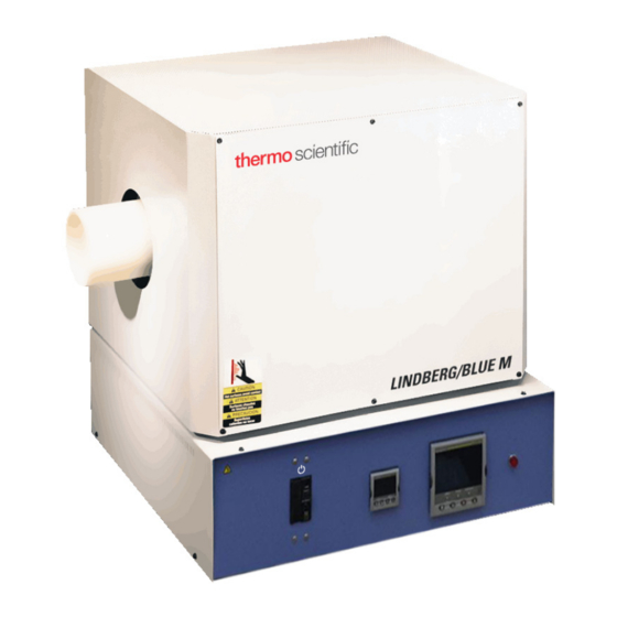
Introduction | Chapter 2 Introduction Thermo Fisher Scientific STF55433 is a reliable, energy efficient 1500°C laboratory tube furnace designed for years of dependable laboratory service. The Silicon Carbide heating ® elements and low thermal mass Moldatherm insulation provide fast duty cycles, energy conservation, and efficient programming. -
Page 16: Non-Intended Use
This furnace is equally unsuitable for the heat treatment of combustible dusts and fibrous materials. Specifications Figure 1 Laboratory Tube Furnace Table 1 Thermo Fisher Scientific STF55433 Series Tube Furnaces STF55433BC-1 STF55433PBC-1 Model STF55433BCOMC-1* STF55433PBCOMC-1* Heating Zone 30.5 cm (12 in) -
Page 17: Pre-Installation
Operating Conditions High concentrations of sulfates, chlorides, fluorides, alkalis and V 2 O 5 can have corrosive effects on the ceramic fiber. Contact Thermo Scientific for additional information about the effects of specific atmospheres on furnace performance. With prolonged use, hairline cracks can develop in the insulation materials. These minor cracks will not affect the furnace's performance. -
Page 18: Atmosphere Systems
| Pre-Installation Chapter 3 Atmosphere Systems The STF55433 Series tube furnaces are designed for use with combustible or inert atmospheres when contained in a process tube. WARNING : Do not use combustible gases directly in this furnace. Process gasses must always be contained in a separate tube. -
Page 19: Installation
12"(30.48 cm) of space on all sides of the unit and 12"(30.48 cm) above the unit. Wiring For detailed wiring information, refer to: Figure 13 “Wiring Diagram STF55433 series” Figure 14 “Wiring Diagram STF55433P Series” at the end of this manual. -
Page 20: Figure 2 Control Wiring
Relay Figure 2 Control Wiring 240 VAC Operation The STF55433 models are 240 VAC furnaces. Power and ground wires are not provided with these furnaces. Note that the heating elements also must be installed (Refer to Section “Heating Elements”). 1. Determine the length of wire needed to connect the furnace to the power source. -
Page 21: Thermocouple Check
Installation | Chapter 4 208 VAC Operation The tube furnace heating elements are specifically designed for operation on 208 or 240 VAC. A furnace wired for 240 VAC operation can also operate on 208 VAC. However, heat up and recovery times will be longer. Thermocouple Check Figure 3 Thermocouple Check that the thermocouple is securely mounted and undamaged. -
Page 22: Heating Elements
WARNING : Disconnect furnace from main power before attempting any maintenance to furnace or its controls. The STF55433 furnaces require installation of the heating elements before operation. The furnace is shipped with eight individually-wrapped silicon carbide heating elements and a bag of ceramic wool for insulation. -
Page 23: Figure 4 Heating Element Installation
Installation | Chapter 4 11. Replace front and back furnace panels. CAUTION : When packing ceramic wool around heating elements, make sure the heating elements are not damaged. Exercise caution when handling due to the fragility of the heating elements. Heating Element Installation Figure 4 1500°C Tube Furnace... -
Page 24: Figure 5 Customer Wiring
| Installation Chapter 4 Heating elements connection Heating elements connection Rear side FAR side Figure 5 Customer Wiring 4-22 1500°C Tube Furnace 305435H03... -
Page 25: Tube Adapters
Installation | Chapter 4 Tube Adapters CAUTION : Do not operate the furnace without properly sized and installed tube adapters. Install tube adapters to each end of the furnace, through the tube adapter at the end, through the furnace chamber below careful. Do not touch / Burn the elements, allow and push through tube adapter on opposite end of furnace. - Page 26 | Installation Chapter 4 4-24 1500°C Tube Furnace 305435H03...
-
Page 27: Start-Up
Start-Up | Chapter 5 Start-Up CAUTION : Observe the following precautions when operating the furnace: Never stand at the ends of the furnace without proper protection. Wear protective eyeware. Wear protective gloves. Use tongs to insert and remove furnace load. ... - Page 28 | Start-Up Chapter 5 5-26 1500°C Tube Furnace 305435H03...
-
Page 29: Chapter 6 Main Controller: 5X16 Segment Programmable
Main Controller: 5x16 Segment Programmable Eurotherm 3216 Controller The Eurotherm 3216p temperature controller senses the furnace's chamber air temperature (the PV or process value) and provides the heat needed to reach the required set point. The 3216p controller offers single setpoint and 5-program 16-segment, this controller can store upto 5-different programs and each program can contain 16 segments. -
Page 30: Operator Interface & Home Display
| Main Controller: 5x16 Segment Programmable Chapter 6 Operator Interface & HOME Display When the controller is turned ON, it will perform a brief self-test and then display the HOME Display page. The measured value (process value) is found in the upper display and the set point is found in the lower display. -
Page 31: Operator Buttons
Main Controller: 5x16 Segment Programmable | Chapter 6 Operator Buttons Press to select a new list of parameters and from any display - press PAGE to return to the HOME Page Press to select new parameter from the page header. If held down, it will continuously scroll through parameters. -
Page 32: Alternate Set Point Selection (Sp2)
| Main Controller: 5x16 Segment Programmable Chapter 6 Alternate Set Point Selection (SP2) 1. Press the SCROLL button from HOME display until SP.SEL is displayed. 2. Press UP or DOWN button to select SP1 or SP2. If SP2 is selected, then SPX beacon will appear on the HOME display indicating the action of alternate set point in use. -
Page 33: View Or Change The Display Units
Main Controller: 5x16 Segment Programmable | Chapter 6 Complete the following steps to change the ramp rate of SSP. 6. Press the SCROLL button until SP.RAT is displayed. 7. Press UP or DOWN button until the desired ramp rate is indicated on the display. -
Page 34: Auto Tuning
| Main Controller: 5x16 Segment Programmable Chapter 6 d. (NONE): No units displayed e. (PERC): Percent NOTE Do not use nonE & PErc, they are used to measure other applications types other than temperature. Auto Tuning In Auto Tuning the characteristics (PID parameters) of the controller are matched to the characteristics of the product load in order to obtain good control. -
Page 35: Parameter List
Main Controller: 5x16 Segment Programmable | Chapter 6 5. Press the PAGE button to return to the HOME display. The display will flash TUNE to indicate that tuning is in progress. The auto tune is completed when the regular display of the measured temperature is shown and the process is allowed to control at the target set point using the new control terms. - Page 36 | Main Controller: 5x16 Segment Programmable Chapter 6 Operator Level 2 Operator Level 2 provides access to additional parameters and this access is protected by a security code. The Level 2 access should typically be granted to a specially trained person, since changing parameters can have major impact on the temperature performance of the furnace.
-
Page 37: Offset Procedure
Main Controller: 5x16 Segment Programmable | Chapter 6 To Return to Level 1 1. Press and hold PAGE button to show the current operator level. 2. Press UP or DOWN button to select LEv1. When Level 1 is selected the display reverts to the HOME display. A passcode is not required when moving from a higher level to a lower level. -
Page 38: Alarms & Diagnostics
| Main Controller: 5x16 Segment Programmable Chapter 6 To Apply an Offset Connect the input of the controller to the source device which you wish to calibrate to. Set the source to the desired calibration value. The controller will display the current measurement of the value. -
Page 39: Sensor Break & Loop Break Protection
Main Controller: 5x16 Segment Programmable | Chapter 6 Sensor Break & Loop Break Protection Sensor Break Protection - The controller provides sensor break protection in the event the thermocouple opens. If an open thermocouple condition occurs, the digital display will blink “S.br”, a red alarm beacon will be illuminated and the power to the heating element will be shut off. - Page 40 | Main Controller: 5x16 Segment Programmable Chapter 6 Program/Timer Segment Types Each program is made of multiple segments. Generally a program segments consist of a controlled rate ramp to a target set point followed by a dwell at that set point. These values can be set by the user.
-
Page 41: 5-Program 16-Segment Controller Operation
Main Controller: 5x16 Segment Programmable | Chapter 6 5-Program 16-Segment Controller Operation The 3216p temperature process controller is a single loop PID based controller that can store up to 5 programs with 16 segments each. This controller consists of microprocessor based three-mode PID (Proportional, Integral, and Derivative), programmable temperature controller and appropriate output switching devices to control the furnace. - Page 42 | Main Controller: 5x16 Segment Programmable Chapter 6 Page Parameter Description Level Access Value Proportional Band Level 2 Read/Write Integral Time Level 2 Read/Write Derivative Time Level 2 Read/Write Loop Break Time Level 2 Read/Write 30 mins 6-31 PV.OFS PV Offset Level 2 Read/Write 6-30...
- Page 43 Main Controller: 5x16 Segment Programmable | Chapter 6 1. Press SROLL button until display reads, “H.back” 2. Press the UP or DOWN button to set holdback value or to turn off holdback function. Creating a New Program or Editing an Existing Program 3216p is a 16 segment programmer consisting of eight ramp/ dwell pairs.
- Page 44 | Main Controller: 5x16 Segment Programmable Chapter 6 SCROLL button through parameters in Level 2 and set the required End.T by pressing UP or DOWN button. To Configure the Programmer 1. Enter Level 2: refer to section “To Enter Level 2” for steps to enter Level 2. 2.
- Page 45 Main Controller: 5x16 Segment Programmable | Chapter 6 7. To set the first Ramp rate, press SCROLL button to select ‘RMP.1’. Press DOWN or UP button to set the value. 8. To set the first Dwell, press SCROLL button to select ‘DWEL.1’. Press DOWN or UP button to set the value.
- Page 46 | Main Controller: 5x16 Segment Programmable Chapter 6 NOTE The program ramp rate is designed to reduce the heating rate or cooling rate that the furnace normally exhibits. When not using this feature, the furnace will operate at its maximum heating and cooling capability. When the program ramp has ended or has been reset, the furnace will continue ...
-
Page 47: Chapter 7 Main Controller: 25X500 Segment Programmable
Main Controller: 25x500 Segment Programmable | Chapter 7 Main Controller: 25x500 Segment Programmable Eurotherm 3504 Controller The 3504 temperature process controller is a single Loop PID based controller that can store up to 25 programs with up to 500 Segments. A 'Factory' code used to configure all the functions essential for temperature controlling process This includes input sensor type, measurement range, control options and alarms. -
Page 48: 3504 Controller Home Display
| Main Controller: 25x500 Segment Programmable Chapter 7 3504 Controller HOME display Beacon Display and Description Beacon Description In a single loop controller OP1 indicates when HEAT is ON MAN illuminates if Loop 1 is in manual mode. (The outputs from the controller are connected to devices on the plant which cause the heating (or cooling) demand to be adjusted resulting in a change in PV which, in turn, is measured by the sensor. -
Page 49: The Operator Buttons
Main Controller: 25x500 Segment Programmable | Chapter 7 Beacon Description PROG To select the program summary page. RUN / HOLD Press once to start a program. ‘RUN’ will be indicated. Press again to hold a program. ‘HLD’ will be indicated. Press and hold for at least two seconds to reset a program. -
Page 50: To Select Manual Operation
| Main Controller: 25x500 Segment Programmable Chapter 7 Action Key Presses Jump to HOME display Press Alarm Ack/reset Press when the HOME screen is being displayed to jump to the ‘Acknowledge All alarms’ page. Pressing acknowledges all alarms if it can. Pressing cancels the operation. -
Page 51: Program Segment Types
Main Controller: 25x500 Segment Programmable | Chapter 7 Parameter Description Value Access Integral Time Integral Time Level2 Derivative Time Derivative Time Level2 Range High Range High Limit 1525 Read Only Range Low Range Low Limit Read Only L2 pass code L2 pass word Read Only Customer ID... - Page 52 | Main Controller: 25x500 Segment Programmable Chapter 7 Step The setpoint changes instantaneously from its current value to a new value at the beginning of a segment. A Step segment has a minimum duration of 1 second. Time A time segment defines the duration of the segment. In this case the target setpoint is defined and the time taken to reach this value.
- Page 53 Main Controller: 25x500 Segment Programmable | Chapter 7 Call A CALL segment is only available when single programmer mode is configured. CALL segments may only be selected in instruments offering multiple program storage. The CALL segment allows programs to be nested within each other. To prevent re-entrant programs from being specified, only higher number programs may be called from a lower program.
-
Page 54: Programmer Types
| Main Controller: 25x500 Segment Programmable Chapter 7 The End segment can be configured to have an indefinite dwell at the last target setpoint or to reset to the start of the program or to go to a defined level of power output (SafeOP). This is selectable by the user. - Page 55 Main Controller: 25x500 Segment Programmable | Chapter 7 Program Edit Summary Parameters: The table below shows a list of all possible parameters which may be set up in operator Levels 1 and 2 using the procedure in the below programming example. Parameter Name Parameter Description Value...
-
Page 56: To Select And Run A Program
| Main Controller: 25x500 Segment Programmable Chapter 7 To Select and Run a Program This example assumes the program to be run has already been entered, to create program follow steps as in the “Create a Program” 1. Press PROG button. 2. -
Page 57: Steps To Edit The Target Sp And Duration
Main Controller: 25x500 Segment Programmable | Chapter 7 5. To HOLD a program, press RUN/HOLD button. 6. Press RUN/HOLD button again to continue the program. 7. To Reset a program, Press and hold RUN/HOLD button for at least 3 seconds. Program will be re-started from beginning at the first program step. - Page 58 | Main Controller: 25x500 Segment Programmable Chapter 7 6. Change the segment1 Target SP by pressing Lower or Raise button with desired value, the controller will accept the new value, which is indicated by a brief flash of the display. 7.
- Page 59 Main Controller: 25x500 Segment Programmable | Chapter 7 12. Modify segment4 Duration by pressing Lower or Raise button (HH:MM format), the controller will accept the new value which is indicated by a brief flash of the display. 13. Press SCROLL button until segment5 Target SP is selected. 14.
-
Page 60: To Create A Program
| Main Controller: 25x500 Segment Programmable Chapter 7 To Create a Program 1. Press PROG button. 2. Press PAGE button. 3. Select the program from available programs of 4 to 25 which are empty. 4. Press SCROLL button to edit the program. 5. - Page 61 Main Controller: 25x500 Segment Programmable | Chapter 7 10. Press SCROLL to select Segment1 Target SP, modify Target SP as per the requirement with the Lower or Raise button, the controller will accept the new value which is indicated by a brief flash of the display. 11.
-
Page 62: To Change The Access Level From L1 To L2 (Level 1 To Level 2)
| Main Controller: 25x500 Segment Programmable Chapter 7 15. To end the program select segment type as END and END Type as SafeOP with the Lower or Raise button. In some cases, program segment can be selected as Dwell to maintain constant setpoint for a duration as per the requirements. -
Page 63: Auto Tune
Main Controller: 25x500 Segment Programmable | Chapter 7 Auto Tune Auto Tune is used to set the control terms (PID values) as close as possible to match the characteristics of the process. It uses the auto tuner which works by switching the output on and off to induce an oscillation in the process value. - Page 64 | Main Controller: 25x500 Segment Programmable Chapter 7 5. Change the Tune value ON with UP button. 6. Press PAGE + SCROLL buttons to start the Auto tune process. 7. Controller begin the Auto tuning process. 8. Once after Auto tune, new PID value will be loaded in to the controller with respective to the tuned SP value.
- Page 65 Main Controller: 25x500 Segment Programmable | Chapter 7 Figure 7 Graph data without Auto tune(Shown example for 1500°C Furnaces) Figure 8 Graph data with Auto tune(Shown example for 1500°C Furnaces) 1500°C Tube Furnace 305435H03 | 7-63...
-
Page 66: To Change The Display Units
| Main Controller: 25x500 Segment Programmable Chapter 7 To Change the Display Units Units of measure can be altered in Level 1 access 1. Press PAGE until below image is displayed on the screen. 2. Press RAISE button to change the Units type to F. 3. -
Page 67: To Change The Pv Offset
Main Controller: 25x500 Segment Programmable | Chapter 7 4. Display Units will be updated from Celsius to Fahrenheit. To Change the PV Offset 1. Get the Level 2 access to adjust the process offset value. 2. Press PAGE until following image is displayed on the screen. 3. -
Page 68: To Change The Alarm Values
| Main Controller: 25x500 Segment Programmable Chapter 7 4. Modify PV offset value as per requirement, the controller will accept the new value which is indicated by a brief flash of the display. To Change the ALARM Values 1. Get the Level 2 access to adjust the ALARM Values. 2. - Page 69 Main Controller: 25x500 Segment Programmable | Chapter 7 4. Press SCROLL button to select Alarm2 Low threshold value. 5. Press RAISE/LOWER buttons to change Alarm2 Low Threshold value, the controller will accept the new value and is indicated by a brief flash of the display. 6.
-
Page 70: To Change The Alarm3 And Its Hysteresis Values (Deviation Alarm)
| Main Controller: 25x500 Segment Programmable Chapter 7 To Change the ALARM3 and its HYSTERESIS values (Deviation Alarm) 1. Press PAGE until following image is shows on the display. 2. Press SCROLL to select Alarm3 Threshold value. 3. Press raise/lower buttons to change Alarm3 Deviation value, the controller will accept the new value which is indicated by a brief flash of the display. - Page 71 Main Controller: 25x500 Segment Programmable | Chapter 7 5. Press Raise button to change Alarm3 Hysteresis value, the controller will accept the new value which is indicated by a brief flash of the display. NOTE Alarm1 HIGH Threshold value should not be greater than 1525°C Deviation High - an alarm occurs when the PV is higher than the setpoint by a set threshold.
- Page 72 | Main Controller: 25x500 Segment Programmable Chapter 7 7-70 305435H03 1500°C Tube Furnace...
-
Page 73: Chapter 8 Operation - 3216I Over Temperature Controller
Operation - 3216i Over Temperature Controller | Chapter 8 Operation - 3216i Over Temperature Controller The 3216i controller serves as the Excess Temperature controller, when installed in the unit, provides an additional, independent temperature control system to help protect products from excess temperatures. The excess temperature controller is a single setpoint controller, which provides a single digital display to indicate the setpoint temperature (excess temperature Alarm threshold). -
Page 74: Over Temperature Controller Operation
| Operation - 3216i Over Temperature Controller Chapter 8 Table 5 Default settings for the Excess temperature controller (STF55433BC-1, STF55433BCOMC-1) Parameter Description Level Access ALARM.1.Threshold Excess temp threshold 1550°C Level 1+2 Read/Write ALARM.1.Hysteresis Alarm Hysteresis 1°C Level 2 Read only INPUT.Units Display Units °C... -
Page 75: Operational Instructions
Operation - 3216i Over Temperature Controller | Chapter 8 Units of Measure Measured Temperature (or process value ‘PV’) Indicates Alarm Alarm value Page Button Up Arrow Button Scroll Button Down Arrow Button Buttons and Indicators PAGE button: Allows you to select a new list of parameters SCROLL button: Allows you to select a parameter within a list of parameters. - Page 76 | Operation - 3216i Over Temperature Controller Chapter 8 2. To change the Display Units: Press SCROLL button until “UNITS” is displayed, then change the desired unit’s type with up/down arrow. A few seconds after the button is released, the controller will accept the new value and is indicated by a brief flash of the display.
- Page 77 Operation - 3216i Over Temperature Controller | Chapter 8 5. To change the ALARM HYSTERSIS Press the SCROLL button until “A1.HYS” is displayed, then press the UP or DOWN button for the desired HYSTERSIS value is displayed and then release the button. A few seconds after the button is released, the controller will accept the new value and is indicated by a brief flash of the display.
- Page 78 | Operation - 3216i Over Temperature Controller Chapter 8 7. To REST the Peak High Temperature rating Press scroll button until “P.RST” shows on the screen. Press UP or DOWN button to rest peak values to the current process values. Value Options 0 (OFF): Peak values not reset 1 (ON): Peak values reset...
- Page 79 Operation - 3216i Over Temperature Controller | Chapter 8 10. TIME Press SCROLL button until TIME shows on the controller display. The value shown on display is Time in Alarm. (example: below image shows ALARM ON time, since the alarm raised on the controller) 11.
- Page 80 | Operation - 3216i Over Temperature Controller Chapter 8 8-78 305435H03 1500°C Tube Furnace...
-
Page 81: Communication Option
Communication Option | Chapter 9 Communication Option The factory installed optional RS 485 Digital Communications Port allows controller to be connected to a PC for remote monitoring and control of the furnace. The equipment with communication option (COM) is equipped with two DB9 serial ports (1 Male port & 1 Female port). -
Page 82: 3504_Controller Parameters For Communication
| Communication Option Chapter 9 3504_Controller Parameters for Communication Table 4 3504 Controller Parameters for Communication Parameter Value Comms Module Identity Comms (67) Communications Protocol Modbus Baud Rate 9600_baud (0) Parity even(1) Comms Address Comms Wait States No (0) Single value Broadcast Enable No (0) Network Watchdog Flag Off (0) -
Page 83: Chapter 10 Maintenance & Cleaning
Maintenance & Cleaning | Chapter 10 Maintenance & Cleaning CAUTION : Maintenance should only be performed by trained personnel. WARNING : Disconnect furnace from main power before attempting any maintenance to furnace or its controls. WARNING : Use appropriate Personal Protective Equipment (PPE) per local protocols. - Page 84 3. Note polarity and thermocouple wire location. Remove the terminal screws and remove the thermocouple lead wires. Refer to Figure 13 “Wiring Diagram STF55433 series”, 14 “Wiring Diagram STF55433P Series”...
-
Page 85: Heating Element Replacement
WARNING : Disconnect furnace from main power before attempting any maintenance to furnace or its controls. The STF55433 heating elements must be matched in Amps values. Perform a continuity check on the elements to determine which element is bad. Mark the other elements with Amp Value. -
Page 86: Control Module Replacement
| Maintenance & Cleaning Chapter 10 9. Slide the rest of the elements into the terminal holes and pack ceramic wool around each element. 10. Use the expansion tool to spread a C clamp and place the clamp over a braided wire and element connection. -
Page 87: Solid- State Relay Replacement
Maintenance & Cleaning | Chapter 10 1. Disconnect main power and switch the circuit breaker to the OFF position. 2. Remove the two screws located on each side of the furnace near the lower front. Pull the control panel forward and swing to the horizontal position to access the module. NOTE If the control panel does not detach easily, insert the blade of a small screwdriver between the panel and the side of the control and gently pry the control panel out. -
Page 88: Control Fuse Replacement
| Maintenance & Cleaning Chapter 10 WARNING : Disconnect furnace from main power before attempting any maintenance to furnace or its controls. Remove the five screws located on the control back panel. 1. Swing the panel down to the horizontal position. 2. - Page 89 Maintenance & Cleaning | Chapter 10 4. Operate the furnace to a stable 500°C temperature setpoint. 5. Make temperature setpoint to 700°C to cause full amp draw on elements. 6. Measure and record the Amps at ONE Element. An Amp Clamp around the braided strap for each element would be an appropriate measuring location.
-
Page 90: Cleaning And Decontamination
| Maintenance & Cleaning Chapter 10 NOTE An Element Set is defined as the group of Elements that are powered from the same electrical supply. Often the Elements are connected electrically in series. Each Element set should have elements that are within 2 amps of each other. For example, an eight-element set may properly have elements measuring 15, 15, 15, 16, 16. -
Page 91: Troubleshooting
Troubleshooting | Chapter 11 Troubleshooting WARNING : Troubleshooting procedures involve working with high voltages which can cause injury or death. Troubleshooting should only be performed by a qualified technician. This section is a guide to troubleshooting furnace problems. Table 6 Controller Troubleshooting for 3504 & 3216p Problem Probable Cause Solution... - Page 92 | Troubleshooting Chapter 11 Table 7 Troubleshooting Furnace problems Problem Solution Furnace Temp If the unit heats past set-point but heating stops at Hi temp Exceeds Setpoint. alarm and element power on light extinguishes check the solid-state relay. First disconnect power from the furnace and remove the controller leads to solid state relay.
-
Page 93: Wiring Diagrams
Wiring Diagrams | Chapter 12 Wiring Diagrams Figure 13 Wiring Diagram STF55433 series 1500°C Tube Furnace 305435H03 | 12-91... - Page 94 | Wiring Diagrams Chapter 12 Figure 14 Wiring Diagram STF55433P Series 12-92 1500°C Tube Furnace 305435H03...
-
Page 95: Replacement Parts
Replacement Parts | Chapter 13 Replacement Parts Table 8 Model STF55433, Tube Furnaces, 1500°C Description Item STF55433BC-1 STF55433BCOMC-1 Heating Element 7217-2277-092 Thermocouple Type “R” 7299-1210-00X Assembly Double Element Straps Single loop 6 in. long 22272-002 Double loop 4.in long 22271-002 Double loop 6.in long... - Page 96 | Replacement Parts Chapter 13 Table 9 Model STF55433P series, Tube Furnaces, 1500°C Description Item STF55433PBC-1 STF55433PBCOMC-1 Heating Element 7217-2277-092 Thermocouple Type “R” 7299-1210-00X Assembly Double Element Straps Single loop 6 in. long 22272-002 Double loop 4.in long 22271-002 Double loop 6.in long 22271-003 Element Terminal Clamp 22080-020...
-
Page 97: End Of Life Care
End of Life Care | Chapter 14 End of Life Care Be sure to follow local regulations when disposing of any unit. Some additional suggestions are listed below: Be sure to clean up any biological safety hazards Have a certified technician remove the insulation from the unit then dispose per SDS ... -
Page 98: Weee Compliance
Further information on our compliance with these Directives, the recyclers in your country, and information on Thermo Scientific products which may assist the detection of substances subject to the RoHS Directive are available at www.thermofisher.com/ Deutschland WEEE Konformittät. -
Page 99: Contact Information
Contact Information | Chapter 15 Contact Information Thermo Fisher Scientific products are backed by a global technical support team ready to support your applications. Visit www.thermofisher.com or call: Countries Sales North America +1 866 984 3766 India toll free 1800 22 8374 India +91 22 6716 2200 China... - Page 100 Find out more at thermofisher.com...
Need help?
Do you have a question about the STF55433 and is the answer not in the manual?
Questions and answers