Table of Contents
Advertisement
Quick Links
Advertisement
Table of Contents
Troubleshooting

Summary of Contents for HEIDENHAIN MSE 1000
- Page 1 MSE 1000 Operating Instructions for use with MSEsetup v2.1.x English (en) 10/2015...
- Page 2 Product overview Product overview Front MSE 1201 ID 747501-01 Front MSE 1201 ID 747501-02 Front MSE 1202 ID 747502-0x HEIDENHAIN | MSE 1000 | Operating Instructions | 10/2015...
- Page 3 Front MSE 1114 ID 747499-0x Front MSE 1314 ID 747503-0x Front MSE 1318 ID 747504-0x HEIDENHAIN | MSE 1000 | Operating Instructions | 10/2015...
- Page 4 Product overview Front MSE 1124 ID 747511-0x Front MSE 1324 ID 747512-0x Front MSE 1328 ID 747513-0x HEIDENHAIN | MSE 1000 | Operating Instructions | 10/2015...
- Page 5 Front MSE 1184 ID 747500-0x Front MSE 1384 ID 747505-0x Front MSE 1388 ID 747506-0x HEIDENHAIN | MSE 1000 | Operating Instructions | 10/2015...
- Page 6 Product overview Front MSE 1332 ID 747509-0x Front MSE 1358 ID 747514-0x HEIDENHAIN | MSE 1000 | Operating Instructions | 10/2015...
- Page 7 Front MSE 1401 ID 747507-01 Front MSE 1401 ID 747507-02 Front MSE 1501 ID 747508-0x HEIDENHAIN | MSE 1000 | Operating Instructions | 10/2015...
- Page 8 Product overview Top MSE 1201 ID 747501-0x Top MSE 1202 ID 747502-0x Top MSE 1114, MSE 1318, MSE 1184, MSE 1388 Top MSE 1314, MSE 1384, MSE 1401, MSE 1501 HEIDENHAIN | MSE 1000 | Operating Instructions | 10/2015...
- Page 9 Rear MSE 1201, MSE 1202, MSE 1114, MSE 1318, MSE 1184, MSE 1388 Rear MSE 1314, MSE 1384, MSE 1401, MSE 1501 HEIDENHAIN | MSE 1000 | Operating Instructions | 10/2015...
- Page 10 Product overview Left side Right side HEIDENHAIN | MSE 1000 | Operating Instructions | 10/2015...
-
Page 11: Table Of Contents
Software setup..........................49 Commissioning and preparing to measure................. 77 Operating information......................... 114 10 Installation and commissioning examples................125 11 Maintenance..........................137 12 Troubleshooting..........................140 13 Decommissioning......................... 165 14 Technical specifications........................167 15 Index...............................180 HEIDENHAIN | MSE 1000 | Operating Instructions | 10/2015... - Page 12 Contents HEIDENHAIN | MSE 1000 | Operating Instructions | 10/2015...
- Page 13 How to use these instructions......................28 Hazard warnings shown in these instructions................. 28 Menu and screen images shown in these instructions..............29 Fonts used in these instructions......................29 Software version..........................29 HEIDENHAIN | MSE 1000 | Operating Instructions | 10/2015...
- Page 14 Contents Model information..........................30 HEIDENHAIN | MSE 1000 | Operating Instructions | 10/2015...
- Page 15 Safety............................... 31 Safety symbols............................. 31 HEIDENHAIN | MSE 1000 | Operating Instructions | 10/2015...
- Page 16 Contents Mounting............................32 Mounting a module..........................34 Connecting modules..........................35 Installing end covers..........................36 Installing cable mounting hardware....................36 Releasing a module..........................37 HEIDENHAIN | MSE 1000 | Operating Instructions | 10/2015...
- Page 17 5.2.9 Connecting an I/O terminal block power connector..............46 5.2.10 Wiring an M8 connector......................46 5.2.11 Connecting a cable with an M8 connector................47 5.2.12 Connecting and disconnecting a compressed air tube............47 HEIDENHAIN | MSE 1000 | Operating Instructions | 10/2015...
- Page 18 Contents Initial power-up..........................48 Power cycling............................48 HEIDENHAIN | MSE 1000 | Operating Instructions | 10/2015...
- Page 19 7 .4.6 Virtual keypad...........................67 7 .4.7 Units of measurement......................68 7 .4.8 Diagnostics mode........................69 7 .4.9 Display formats........................70 7 .4.10 Enable/disable prompts......................71 7 .4.11 File options..........................71 7 .4.12 Update firmware........................75 HEIDENHAIN | MSE 1000 | Operating Instructions | 10/2015...
- Page 20 Configuring the module chain with DHCP................87 8.1.8 Configuring the module chain manually.................. 89 Module setup............................91 8.2.1 LVDT calibration........................93 8.2.2 LVDT Teach resolutions......................95 Channel setup............................97 Device setup............................103 Referencing............................109 Mastering............................111 HEIDENHAIN | MSE 1000 | Operating Instructions | 10/2015...
- Page 21 Operating information......................... 114 Toggle output state........................... 114 Capturing data............................114 Logging..............................118 9.3.1 Service log..........................120 Asynchronous message thread......................121 9.4.1 Asynchronous commands......................121 9.4.2 Visual Basic for Applications (VBA)..................123 HEIDENHAIN | MSE 1000 | Operating Instructions | 10/2015...
- Page 22 10.2.15 Configure the EnDat module network communication settings..........135 10.2.16 Setup the 1 V channel......................135 10.2.17 Setup the 1 V encoder....................... 136 10.2.18 Setup the EnDat channel.......................136 10.2.19 Setup the EnDat encoder...................... 136 HEIDENHAIN | MSE 1000 | Operating Instructions | 10/2015...
- Page 23 11 Maintenance..........................137 11.1 Cleaning...............................138 11.2 Replacing a fuse..........................138 HEIDENHAIN | MSE 1000 | Operating Instructions | 10/2015...
- Page 24 12.10 Referencing warning.......................... 159 12.11 Referencing error..........................159 12.12 Log file warnings and errors......................160 12.13 Network troubleshooting........................161 12.13.1 Command line tools.......................161 12.13.2 Basic network troubleshooting....................162 12.13.3 Recovering from IP address conflicts..................164 HEIDENHAIN | MSE 1000 | Operating Instructions | 10/2015...
- Page 25 13 Decommissioning......................... 165 13.1 Power-off..............................165 13.2 Disconnect power cords........................166 13.3 Disconnect data interface connections....................166 13.4 Release all modules........................... 166 HEIDENHAIN | MSE 1000 | Operating Instructions | 10/2015...
- Page 26 ............................... 177 14.5.7 ............................... 177 14.5.8 ............................... 177 14.5.9 ............................... 177 14.5.10 ............................... 178 14.5.11 ............................... 178 14.5.12 ............................... 178 14.5.13 ............................... 178 14.6 Relay outputs............................. 179 14.7 Switching inputs..........................179 HEIDENHAIN | MSE 1000 | Operating Instructions | 10/2015...
- Page 27 15 Index...............................180 HEIDENHAIN | MSE 1000 | Operating Instructions | 10/2015...
-
Page 28: How To Use These Instructions
An informational box gives important or additional information about an activity or concept. It also brings your attention to situations or circumstances that can lead to measuring errors or malfunctions. HEIDENHAIN | MSE 1000 | Operating Instructions | 10/2015... - Page 29 Software version Menu and screen images shown in these instructions MSEsetup is a PC application designed to communicate with MSE 1000 modules. Menu and screen images often accompany text to clarify or emphasize product concepts. Screen images might reflect different MSEsetup configurations depending on the concepts presented.
-
Page 30: Model Information
Verify that these instructions are valid by matching the Index on the label with the Index listed at www.heidenhain.de. If these instructions are not valid, download the applicable Instructions from www.heidenhain.de. An index may not be present on all products. HEIDENHAIN | MSE 1000 | Operating Instructions | 10/2015... -
Page 31: Safety
Symbol Description Refer to the accompanying information or documentation to protect against personal injury or damage to the unit. Power switch “On (supply)” position. Power switch “Off (supply)” position. HEIDENHAIN | MSE 1000 | Operating Instructions | 10/2015... -
Page 32: Mounting
Mounting stand 19" mounting cabinet In its basic configuration, the MSE 1000 consists of a power supply module and a base module. It can be expanded by further modules as needed. In all, up to 250 axes or channels can be configured. - Page 33 The power consumption is specified for each module (see table). The power consumption of the connected HEIDENHAIN encoders can be calculated from the catalog data (supply voltage x current consumption). For all other consumers (e.g.
-
Page 34: Mounting A Module
While maintaining upward pressure, rotate the top of the module towards the DIN rail until the top channel of the module is aligned above the DIN rail. Gently release the upward pressure, locking the module onto the DIN rail. HEIDENHAIN | MSE 1000 | Operating Instructions | 10/2015... -
Page 35: Connecting Modules
Slide the right module to the left until the lock tab of the left module engages with the lock tab receiver of the right module. HEIDENHAIN | MSE 1000 | Operating Instructions | 10/2015... -
Page 36: Installing End Covers
Insert the M3 screw through the cable tie holder and fasten to the M3 hex nut using a cross-head screwdriver. Insert the cable tie through the cable tie holder and fasten cables. HEIDENHAIN | MSE 1000 | Operating Instructions | 10/2015... -
Page 37: Releasing A Module
Gently apply upward pressure, depressing the DIN rail spring 32. While maintaining upward pressure, rotate the top of the module away from the DIN rail. Gently release the upward pressure, releasing the module from the DIN rail. HEIDENHAIN | MSE 1000 | Operating Instructions | 10/2015... -
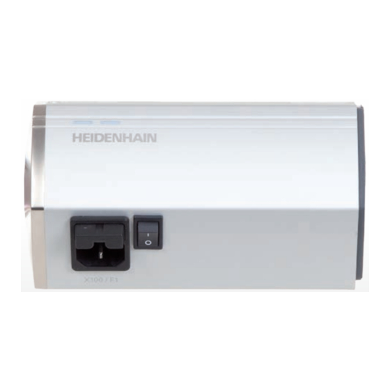
Page 38: Installation
3, 9, 10 Replaceable fuse holder. X100: Power connector. Power switch. 8, 35 Module connectors. X110: Power connector. Replaceable fuse holder. X120: Power connector. X103: Foot switch connection. X116: RJ-45 for network connection. HEIDENHAIN | MSE 1000 | Operating Instructions | 10/2015... - Page 39 3-pin M8: X102 O1, O2, O3, O4 for relay output. 3-pin M8: X101 for I/O power. Plug-in connection for compressed air input. Muffler for pressure relief. Plug-in connection for compressed air output. HEIDENHAIN | MSE 1000 | Operating Instructions | 10/2015...
-
Page 40: Electrical Connection
Protective conductor (ground) ter- Protective conductor (ground) minal(green/yellow) terminal 3-conductor (grounded) Min. wire cross section: 0.24 mm Min. cable cross section: 0.75 mm Max. wire cross section: 0.35 mm Max. cable length: 3 m HEIDENHAIN | MSE 1000 | Operating Instructions | 10/2015... -
Page 41: Wiring The Power Connector
To wire the power connector MSE 1202 (ID 747502-0x): Verify that the power cord is not plugged into the main power supply. Wire the power connector according to the illustration above. HEIDENHAIN | MSE 1000 | Operating Instructions | 10/2015... -
Page 42: Connecting A Power Cord
5.2.1 Connecting a foot switch Foot switch connector This product can be used with HEIDENHAIN foot switch (ID 681041-03). To connect a foot switch: Verify power is removed from all power supply modules in the module chain. Connect the foot switch cable connector to the foot switch connection the module and tighten the cable connector screws until they are snug. -
Page 43: Connecting A Network Cable
5.2.3 Connecting an EnDat encoder EnDat encoder connector This product can be used with HEIDENHAIN length gauges, linear encoders and rotary encoders that provide EnDat signals. The connecting cable must not exceed 100 meters in length. To connect an EnDat encoder: Verify power is removed from all power supply modules in the module chain. -
Page 44: Connecting A Ttl Encoder
5.2.4 Connecting a TTL encoder TTL encoder connector This product can be used with HEIDENHAIN encoders that provide TTL signals. The connecting cable must not exceed 30 meters in length. To connect a TTL encoder: Verify power is removed from all power supply modules in the module chain. -
Page 45: Connecting A Transducer
Using a small flat-edge screwdriver, tighten the screws located on the top of the cable connector. Insert the male terminal connector into the connection on the module. HEIDENHAIN | MSE 1000 | Operating Instructions | 10/2015... -
Page 46: Connecting An I/O Terminal Block Power Connector
A female M8 connector (ID 1071955-01) is included for 5 V power output, external power input and GND for use with relay outputs. Additional connectors can be purchased from HEIDENHAIN. Wire the power connector based on power requirements. M8 connectors need to be wired to a suitable cable. -
Page 47: Connecting A Cable With An M8 Connector
Insert the 4 mm tube into the connector on the front of the module. To disconnect a compressed air tube: Verify that power is off or disconnected. Push in on the blue connector ring and remove the 4 mm tube. HEIDENHAIN | MSE 1000 | Operating Instructions | 10/2015... -
Page 48: Initial Power-Up
Power cycling Power cycling refers to the procedure of turning the power provided to the MSE 1000 modules off and then back on. Power cycling is typically used when troubleshooting communication problems between MSEsetup and the modules and may allow the modules to reinitialize their configuration or recover from an unresponsive state. -
Page 49: Software Setup
Click Finish. File locations Configurable data, log files, and data capture files are stored in the following public locations: Windows XP: C:\Documents and Settings\All Users\HEIDENHAIN\MSEsetup Windows Vista: C:\Users\Public\HEIDENHAIN\MSEsetup Windows 7: C:\Users\Public\HEIDENHAIN\MSEsetup HEIDENHAIN | MSE 1000 | Operating Instructions | 10/2015... -
Page 50: Msesetup Overview
Program group MSEsetup shortcuts are installed in a program group located in the Windows Start menu. These shortcuts can be used to open MSEsetup, MSE 1000 Operating Instructions, the Excel VBA Example, and to Uninstall MSEsetup. To access MSEsetup program group shortcuts: Click the Windows Start menu icon in the taskbar. -
Page 51: Operating Elements
MSEsetup overview 7.2.1 Operating elements Setup and operation of MSE 1000 modules is performed from a workstation PC running the MSEsetup application software. Further Information: "MSEsetup overview", page 50. Operation and navigation in MSEsetup is accomplished through the operating elements described in the following tables. - Page 52 Opens the Data Capture screen. Master: Opens the Mastering screen. Diagnostics: Opens the Diagnostics screen. Config: Opens the System Configuration screen. Connect: Opens the Network Configuration screen. Back: Returns to the previously viewed screen. HEIDENHAIN | MSE 1000 | Operating Instructions | 10/2015...
- Page 53 System directory: Provides quick access to the system folder. User directory: Provides quick access to the user folder. Parent directory: Navigates from the current folder location to its par- ent folder. HEIDENHAIN | MSE 1000 | Operating Instructions | 10/2015...
- Page 54 Sets the minimum position value for all sensors. Minimum position values are used when calculating sensor resolution. SetAllMax: Sets the maximum position value for all sensors. Maxi- mum position values are used when calculating sensor resolution. HEIDENHAIN | MSE 1000 | Operating Instructions | 10/2015...
- Page 55 Available only when supervisor mode is enabled. Diagnostics screen buttons Button Function Function reserves: Opens Function Reserves information for EnDat devices. Warning/Error: Opens the Warnings and Errors screen. HEIDENHAIN | MSE 1000 | Operating Instructions | 10/2015...
- Page 56 Up arrow: Scrolls up one line at a time. Down arrow: Scrolls down one line at a time. Page up: Scrolls up one screen length. Page down: Scrolls down one screen length. HEIDENHAIN | MSE 1000 | Operating Instructions | 10/2015...
- Page 57 MSEsetup overview Keypads Keypad Function Virtual keypad: Allows touch screens to have text entry capabilities. Numeric keypad: Allows touch screens to have number entry capabil- ities. HEIDENHAIN | MSE 1000 | Operating Instructions | 10/2015...
-
Page 58: The Application Window
A dynamic area where operation and setup screens are displayed. Message area Displays warnings and errors and messages related to the current operation. Navigation bar Location of the MSEsetup navigation buttons. HEIDENHAIN | MSE 1000 | Operating Instructions | 10/2015... -
Page 59: Views
Setup, Data, Master, or Diagnostics screen is active. The tree displays the MSE 1000 module chain to the Channel level. Modules are nodes of the main tree. Channels are nodes of their respective module. The Data and Master screens add additional data to the right of the channels. -
Page 60: File Dialog Window
Clicking on a file name will select the file. File name field Field used to enter a file name. File type field Displays the required file type. Confirmation but- Used to confirm or cancel an action. tons HEIDENHAIN | MSE 1000 | Operating Instructions | 10/2015... -
Page 61: Basic Functions
Maximizing the application window Maximize button The MSEsetup application window will fill the full screen width when maximized. To maximize the MSEsetup window: Click the Maximize button to maximize the MSEsetup application window. HEIDENHAIN | MSE 1000 | Operating Instructions | 10/2015... - Page 62 Opening MSEsetup help Help button Each MSEsetup screen has a Help button that can be used to open the MSEsetup Operating Instructions. To open the MSEsetup Operating Instructions: Click the Help button. HEIDENHAIN | MSE 1000 | Operating Instructions | 10/2015...
-
Page 63: Msesetup Configuration
Units of measurement File options Supervisor mode Diagnostics mode Update firmware Temperature units Display formats Configuration Screen Config button To open the Configuration screen: Click the Config button located in the Navigation bar. HEIDENHAIN | MSE 1000 | Operating Instructions | 10/2015... -
Page 64: Language Selection
The updated setting is displayed in the Language selection text box. A pop-up is displayed verifying the language has changed and notifying that MSEsetup will restart. Click the OK button. MSEsetup will restart. Text is now displayed in selected language. HEIDENHAIN | MSE 1000 | Operating Instructions | 10/2015... -
Page 65: Data Capture
Click the Output File Type drop down arrow and select a file type. The updated setting is displayed in the Output File Type text box. A message verifying the action is displayed in the message area. HEIDENHAIN | MSE 1000 | Operating Instructions | 10/2015... -
Page 66: Supervisor Mode
To disable Supervisor mode: Click the Supervisor mode button. The updated setting is displayed in the Supervisor mode text box. A message verifying the action is displayed in the message area. HEIDENHAIN | MSE 1000 | Operating Instructions | 10/2015... -
Page 67: Temperature Units
Click the Virtual keypad button. Clicking the button toggles between the Enabled and Disabled options. The updated setting is displayed in the Virtual keypad text box. A message verifying the action is displayed in the message area. HEIDENHAIN | MSE 1000 | Operating Instructions | 10/2015... -
Page 68: Units Of Measurement
Units of measurement settings are used for selecting the linear and angular units of measure displayed in MSEsetup and included in transmitted or printed data for all encoders in the MSE 1000 module chain. Individual channel units can be to set to a different unit in the Setup screen. -
Page 69: Diagnostics Mode
Click the Diagnostics mode drop down arrow and select a diagnostics mode. The updated setting is displayed in the Diagnostics mode drop down box. A message verifying the action is displayed in the message area. HEIDENHAIN | MSE 1000 | Operating Instructions | 10/2015... -
Page 70: Display Formats
Data screen and transmitted to the output file. Selecting a display format applies the change to all channels in the MSE 1000 module chain that use that format. Individual channels can be to set to a different format in the Setup screen. -
Page 71: Enable/Disable Prompts
File options is available only when supervisor mode is enabled. Configuration file options: SystemConfig.xml ModuleConfig.xml User Directory Save As Save As Select Load Load Restore Merge Defaults Restore Defaults HEIDENHAIN | MSE 1000 | Operating Instructions | 10/2015... - Page 72 Click the OK button. A dialog window appears requesting to back up the log file. Choose whether to back up the file and follow any additional on screen instructions. Once complete MSEsetup will restart. HEIDENHAIN | MSE 1000 | Operating Instructions | 10/2015...
- Page 73 Click the OK button. A dialog window appears requesting to back up the log file. Choose whether to back up the file and follow any additional on screen instructions. Once complete MSEsetup will restart. HEIDENHAIN | MSE 1000 | Operating Instructions | 10/2015...
- Page 74 Use the File dialog window controls to select a location to use as the user directory. Click the OK button. The User Directory location is saved and can be accessed using the User Directory button in the File dialog window. HEIDENHAIN | MSE 1000 | Operating Instructions | 10/2015...
-
Page 75: Update Firmware
MSEsetup configuration 7.4.12 Update firmware The Update firmware screen provides options for updating the firmware and bootloader installed on MSE 1000 modules. Update firmware is available only when supervisor mode is enabled. Update firmware NOTICE Do not update the firmware when Use DHCP addressing is enabled. - Page 76 All is selected. If required, click the Firmware/Bootloader button and select Bootloader. Click the OK button. The bootloader update begins. Refer to the status indicator for the current status of the update. HEIDENHAIN | MSE 1000 | Operating Instructions | 10/2015...
-
Page 77: Commissioning And Preparing To Measure
The workstation must have a Network Interface Controller (NIC) with a unique Internet Protocol (IP) address that is on the same subnetwork as the MSE 1000 modules. All MSE 1000 modules must also have a unique IP address. - Page 78 Network configuration Connect screen Connect button To open the Connect screen: Click the Config button. Click the Supervisor mode button. Enter the supervisor password into the Password field. Click the Connect button. HEIDENHAIN | MSE 1000 | Operating Instructions | 10/2015...
-
Page 79: Workstation Ip
The first drop-down list shows the available IP addresses of the workstation. The IP address of the workstation NIC connected to the MSE 1000 base module should be chosen from the list. If it exists, the default subnetwork is 172.31.46. - Page 80 Network configuration Set Port The Port number is used to receive messages from MSE 1000 modules on the selected IP address. This option only needs to be modified if there is another application using the same IP address and port number.
-
Page 81: Connection
Disconnect The Disconnect option will close the communication connection between the workstation and the MSE 1000 modules. MSEsetup can still be used for viewing logs, configuring network settings, and modifying MSEsetup configurations when disconnected. This choice is not available if a successful Broadcast has not been performed. - Page 82 Click the OK button to overwrite the configurable module settings from a backup file or click the Cancel button to proceed without overwriting the settings. A message verifying that broadcasting is finished is displayed in the Connect screen message area. HEIDENHAIN | MSE 1000 | Operating Instructions | 10/2015...
-
Page 83: Individual Module Ip
Individual Module IP options are used for querying or setting a static IP address for a specific module in the module chain. The Query option is available even when there is not an active connection between the workstation and the MSE 1000 modules. -
Page 84: Module Chain
"Configuring the module chain with DHCP", page 87. DHCP addressing requires a router with a Dynamic Host Configuration Protocol (DHCP) server to be connected between the workstation and the MSE 1000 base module. HEIDENHAIN | MSE 1000 | Operating Instructions | 10/2015... - Page 85 Default network settings: Module IP address Subnet Asynchro- Addressing nous port MSE 120x 172.31.46.2 255.255.255.0 27300 DHCP MSE 11xx, 172.31.46.1 MSE 13xx, MSE 1401, MSE 1501 HEIDENHAIN | MSE 1000 | Operating Instructions | 10/2015...
-
Page 86: Firewall Configuration
8.1.6 Firewall configuration MSEsetup uses the UDP protocol for communication with MSE 1000 modules. By default firewalls may block UDP messages. Network firewall settings may need to be configured to allow UDP on the ports used by MSEsetup and MSE 1000 modules. -
Page 87: Configuring The Module Chain With Dhcp
MSE 1000 modules. A router with DHCP enabled must be connected between the workstation and the MSE 1000 base module. The DHCP server will assign each module a unique IP address. MSE 1000 modules are set to use DHCP by default. - Page 88 Repeat turning the power off, installing up to ten modules, turning the power on, broadcasting, and switching to static addressing until all modules in the module chain have a unique IP address. HEIDENHAIN | MSE 1000 | Operating Instructions | 10/2015...
-
Page 89: Configuring The Module Chain Manually
Network configuration 8.1.8 Configuring the module chain manually The MSE 1000 module chain must be configured manually when a DHCP enabled router is not used. An RJ-45 crossover cable may be required when connecting the workstation directly to the base module. Refer to the documentation provided with the NIC for additional information. - Page 90 Commissioning and preparing to measure Network configuration Configure additional modules MSE 1000 modules must be configured one at a time when configuring the module chain manually. To configure additional modules: Turn the power off. Install the next module into the module chain.
-
Page 91: Module Setup
To view Module setup options: Click the Setup button. Select a module from the Tree or the Module view. The Module setup tab for the selected module appears in the Setup screen. HEIDENHAIN | MSE 1000 | Operating Instructions | 10/2015... - Page 92 Module View will show the inactive module in a lighter tint. To change the active status of a module: Click Active toggle button to change the active status. Click the OK button. HEIDENHAIN | MSE 1000 | Operating Instructions | 10/2015...
-
Page 93: Lvdt Calibration
To view the LVDT calibration screen: Click the Setup button. Select an LVDT module from the Tree or the Module view. Click the calibration button. The LVDT setup screen for the selected module appears. HEIDENHAIN | MSE 1000 | Operating Instructions | 10/2015... - Page 94 A message verifying the action is displayed in the message area. The Exc. (Vpp) will be updated with the new voltage that is being used in the module. This value is affected by both the excitation voltage and the excitation frequency. HEIDENHAIN | MSE 1000 | Operating Instructions | 10/2015...
-
Page 95: Lvdt Teach Resolutions
Select an LVDT module from the Tree or the Module view. Click the Calibration button. Click the OK button to the right of Teach resolutions. The LVDT Teach resolutions screen for the selected module appears. HEIDENHAIN | MSE 1000 | Operating Instructions | 10/2015... - Page 96 Click the SetAllMax button. The resolutions that will be used to convert from volts to millimeters or inches will be displayed in the Res. (mm/V) or Res. (in/V) fields. The Calibration timestamps are updated. HEIDENHAIN | MSE 1000 | Operating Instructions | 10/2015...
-
Page 97: Channel Setup
Compressed air channel assignments are created regardless of an active connection to the channel. Channel tab information: Channel label Angle format Counting Direction Display resolution Error compensation Unit of Measurement Scale Factor Channel setup tab HEIDENHAIN | MSE 1000 | Operating Instructions | 10/2015... - Page 98 Drag the selected encoder graphic away from its current location. The encoder graphic is replaced with the Delete icon. Release the button. The selected encoder is removed from the channel assignment. HEIDENHAIN | MSE 1000 | Operating Instructions | 10/2015...
- Page 99 Drag the selected device graphic over the desired channel square and release the button. The selected device graphic appears below the module with a line connecting the encoder to the channel. HEIDENHAIN | MSE 1000 | Operating Instructions | 10/2015...
- Page 100 Click inside the Channel label text field. Delete the current label. Enter a unique name for the channel. Click the OK button. A message verifying the action is displayed in the message area. HEIDENHAIN | MSE 1000 | Operating Instructions | 10/2015...
- Page 101 To select an angle format: Click the Angle format drop-down arrow and select the desired value. Click the OK button. A message verifying the action is displayed in the message area. HEIDENHAIN | MSE 1000 | Operating Instructions | 10/2015...
- Page 102 To select a counting direction: Click the Counting direction drop-down arrow and select the desired value. Click the OK button. A message verifying the action is displayed in the message area. HEIDENHAIN | MSE 1000 | Operating Instructions | 10/2015...
-
Page 103: Device Setup
Device setup tab To view device setup options: Click the Setup button. Select a channel from the Tree. Click the Device tab. Device information and options are displayed for the selected channel. HEIDENHAIN | MSE 1000 | Operating Instructions | 10/2015... - Page 104 TTL encoders. Reference marks are used to re-establish datum positions after a power interruption. The following table represents a partial list of HEIDENHAIN encoders. This table describes the reference mark parameters that must set for the encoders. Most entries can be found in the operating instructions for the encoder.
- Page 105 20-fold Coded/1000 LS 328C 5 µm 20 µm Coded/1000 LS 628C LS 378C 1 µm 20 µm 5-fold Coded/1000 0.5 µm 20 µm 10-fold Coded/1000 0.25 µm 20 µm 20-fold Coded/1000 HEIDENHAIN | MSE 1000 | Operating Instructions | 10/2015...
- Page 106 Hold the sensor at the minimum or maximum position and click the OK button. A dialog window appears informing if the teach gain passed or failed. The Gain code will be updated with the new value. HEIDENHAIN | MSE 1000 | Operating Instructions | 10/2015...
- Page 107 The resolution will be updated with the interpolated value. The calibration time-stamp will be updated with the current date and time. A message verifying the action is displayed in the message area. HEIDENHAIN | MSE 1000 | Operating Instructions | 10/2015...
- Page 108 Click inside the Recal. timer text field. Delete the current value. Enter the required recalibration timer value. Click the OK button. A message verifying the action is displayed in the message area. HEIDENHAIN | MSE 1000 | Operating Instructions | 10/2015...
-
Page 109: Referencing
Referencing must be completed when: MSEsetup is opened Signal period setting is changed A Reconnect is performed Line count setting is changed Reference mark setting is changed Interpolation setting is changed Referencing screen HEIDENHAIN | MSE 1000 | Operating Instructions | 10/2015... - Page 110 Click the Back button. Click the OK button. A message verifying the action is displayed in the message area. The Tree status will remain a flashing "!ref" when an encoder has not been referenced. HEIDENHAIN | MSE 1000 | Operating Instructions | 10/2015...
-
Page 111: Mastering
Mastering options: Load mastering settings Apply mastering Save mastering settings Unapply mastering Disabling and enabling individual channel mastering Mastering screen HEIDENHAIN | MSE 1000 | Operating Instructions | 10/2015... - Page 112 Click the Enable offset button. Click the Apply all button. The Enable offset button toggles to the Disable offset button. A message veryfying the action is displayed in the message area. HEIDENHAIN | MSE 1000 | Operating Instructions | 10/2015...
- Page 113 If required, use the File dialog window to navigate to the desired directory. Select a file to load. Click the OK button. A message veryfying the action is displayed in the message area. HEIDENHAIN | MSE 1000 | Operating Instructions | 10/2015...
-
Page 114: Operating Information
"Data capture", page 65. Minimum, actual and maximum data values are also available in the Tree by selecting their respective tab. A value of 0 will be displayed when no data has been captured. HEIDENHAIN | MSE 1000 | Operating Instructions | 10/2015... - Page 115 Delete data position data Export data Minimum Excel spreadsheet Actual Comma separated value (CSV) Maximum file Display and capture input and output Save data state Comma separated value (CSV) file Data screen HEIDENHAIN | MSE 1000 | Operating Instructions | 10/2015...
- Page 116 The Data screen is displayed in the content area. A message verifying the action is displayed in the message area. Data capture Data can be captured from MSEsetup or with a HEIDENHAIN foot switch (ID 681041-03). To capture data: Click the OK button in the Data screen.
- Page 117 To view minimum, actual, and maximum data values: Click the Tree tab for the MIN, ACTL, or MAX data value. The selected data values are displayed for all channels in the Tree. HEIDENHAIN | MSE 1000 | Operating Instructions | 10/2015...
-
Page 118: Logging
Further Information: "Log file warnings and errors", page 160. Logging screen options: Save a log file Print a log file Open a saved log file Delete current logging information Logging screen HEIDENHAIN | MSE 1000 | Operating Instructions | 10/2015... - Page 119 The log file is sent to the workstation default printer. Delete log file To delete the log file: Click the Delete button. A dialog window opens to verify the request. Click the OK button. The current log information is deleted. HEIDENHAIN | MSE 1000 | Operating Instructions | 10/2015...
-
Page 120: Service Log
9.3.1 Service log The Service log is used for logging MSE 1000 module networking information collected during a broadcast when the modules are first powered on. Service log information is useful if a module is set to an unknown IP address or netmask. -
Page 121: Asynchronous Message Thread
The asynchronous default port is 27300 and can be changed in the Networking screen. This thread is used to accept asynchronous messages from the MSE 1000 modules as well as from other client applications that want to perform functions through MSEsetup. - Page 122 The value is used to determine which latch line to trig- ger (1-5). A latch command is sent to the modules causing the data to be updated in the Data screen and the Mse1000Data.xlsx Excel spreadsheet. No response is sent back. HEIDENHAIN | MSE 1000 | Operating Instructions | 10/2015...
-
Page 123: Visual Basic For Applications (Vba)
To access the VBA procedures and winsock usage: Enable "Show Developer tab in the Ribbon". Refer to the documentation provided with the software for instructions. Click on the "Developer" tab. Click on "Visual Basic". HEIDENHAIN | MSE 1000 | Operating Instructions | 10/2015... - Page 124 Enter a value of "1" for the relay output value into the Value field. Click Send. The spreadsheet sends a "Set Output" request to the MSEsetup asynchronous thread and the relay output is set High (1). HEIDENHAIN | MSE 1000 | Operating Instructions | 10/2015...
-
Page 125: Installation And Commissioning Examples
Example using DHCP IP address assignment 10.1 Installation and commissioning examples Each MSE 1000 system is unique, but the installation and commissioning of most systems is similiar. Install the MSE 1000 system Configure the MSEsetup software Configure the network communication settings... -
Page 126: Install The End Covers
Refer to the documentation provided with the workstation PC for instructions. Connect the other end of this network cable to one of the LAN ports on the DHCP router. Refer to the documentation provided with the router for connection location. HEIDENHAIN | MSE 1000 | Operating Instructions | 10/2015... -
Page 127: Connect The Encoders
Download and install the MSEsetup application software, see "Installing MSEsetup", page 49. 10.1.9 Open the software Open MSEsetup Double-click the MSEsetup desktop icon to open MSEsetup, see "Basic functions", page 61. HEIDENHAIN | MSE 1000 | Operating Instructions | 10/2015... -
Page 128: Power-Up The Modules
Click and drag the Length Gauge icon to the green square labeled X1. The green square appears when the length gauge icon is clicked and dragged. Click the OK button. Further Information: "Channel setup", page 97 for additional channel settings options. HEIDENHAIN | MSE 1000 | Operating Instructions | 10/2015... -
Page 129: Setup The 1 Vpp Encoder
Disabling error monitoring is useful for increasing communication speed with EnDat v2.2 encoders. Click the Error monitoring drop-down arrow. Select Off. Click the OK button. Further Information: "Device setup", page 103 for additional device settings. HEIDENHAIN | MSE 1000 | Operating Instructions | 10/2015... -
Page 130: Example Using Manual Ip Address Assignment
10.2 Example using manual IP address assignment The following information provides an example for how to install and commission an MSE 1000 system with three modules and two encoders using manual IP address assignment. MSE 1000 modules with encoders: MSE 1201 (ID 747501-01) AC 120 V power supply module... -
Page 131: Install The Software
After a 45 second timeout the modules will stop waiting for DHCP to assign an IP address and the Network LED's on each module will flash green twice per second. Wait for the Network LED to flash green twice per second on all modules. HEIDENHAIN | MSE 1000 | Operating Instructions | 10/2015... - Page 132 Wait for the Network LED's to flash twice per second on all modules. Click the OK button in the dialog box. Click the Cancel button when requested to overwrite the settings from a backup file. HEIDENHAIN | MSE 1000 | Operating Instructions | 10/2015...
-
Page 133: Power-Off The Modules
Mount the MSE 1314 (ID 747503-01) 4-channel EnDat module, see "Mounting a module", page 34. Connect base and EnDat module Connect the base module and the 4-channel EnDat module, see "Connecting modules", page 35. HEIDENHAIN | MSE 1000 | Operating Instructions | 10/2015... -
Page 134: Install The End Covers
Secure all cables to the cable mounting hardware using the supplied cable tie's. 10.2.14 Power-up the modules Power-up Press the On (supply) side of the power switch to power-up the system, see "Initial power-up", page 48. HEIDENHAIN | MSE 1000 | Operating Instructions | 10/2015... -
Page 135: Configure The Endat Module Network Communication Settings
Click and drag the Length Gauge icon to the green square labeled X1. The green square appears when the length gauge icon is clicked and dragged. Click the OK button. Further Information: "Channel setup", page 97 for additional channel settings options. HEIDENHAIN | MSE 1000 | Operating Instructions | 10/2015... -
Page 136: Setup The 1 Vpp Encoder
Disabling error monitoring is useful for increasing communication speed with EnDat v2.2 encoders. Click the Error monitoring drop-down arrow. Select Off. Click the OK button. Further Information: "Device setup", page 103 for additional device settings. HEIDENHAIN | MSE 1000 | Operating Instructions | 10/2015... -
Page 137: Maintenance
Electrical Protective Annual Interrupted or bad Replace power Test ground con- connection cord or contact a nection HEIDENHAIN ser- vice technician HEIDENHAIN | MSE 1000 | Operating Instructions | 10/2015... - Page 138 Risk of electrical shock When replacing a fuse it is possible to touch hazardous live parts. To avoid the hazard, always power off the unit and disconnect the power cable. NOTICE Use only replacement fuses meeting rated specifications to avoid damage to the product. HEIDENHAIN | MSE 1000 | Operating Instructions | 10/2015...
- Page 139 Insert a flat-edge screwdriver into the slot on the fuse holder and turn counterclockwise to disengage the fuse holder Remove the fuse holder and replace the fuse Re-insert the fuse holder and turn clockwise with flat-edge screwdriver until re- engaged HEIDENHAIN | MSE 1000 | Operating Instructions | 10/2015...
-
Page 140: Troubleshooting
Diag button To open the Diagnostics screen: Click the Diag button. The Diagnostics screen is displayed in the content area. A message verifying the action is displayed in the message area. HEIDENHAIN | MSE 1000 | Operating Instructions | 10/2015... -
Page 141: Module Diagnostics
CPU temperature Displays the temperature of the microcontroller CPU in- side the selected module. CPU temperature is available only when supervisor mode is enabled. HEIDENHAIN | MSE 1000 | Operating Instructions | 10/2015... -
Page 142: Device Diagnostics
1 V encoder is operating properly. device diagnostics: Lissajous figure Signal B Amplitude Signal B Symmetry Signal A Amplitude Signal A Symmetry Phase Angle diagnostics screen HEIDENHAIN | MSE 1000 | Operating Instructions | 10/2015... - Page 143 Displays the signal A symmetry reading from the en- coder. Signal B Symmetry Displays the signal B symmetry reading from the en- coder. Phase Angle Displays the phase angle reading from the encoder. HEIDENHAIN | MSE 1000 | Operating Instructions | 10/2015...
- Page 144 EnDat warnings and errors. EnDat warnings and errors: Warnings Errors Frequency Exceeded Light Unit Temperature Exceeded Signal Amplitude Light Control Reserve Position Error Battery Charge Low Overvoltage Traverse Reference Point Undervoltage Overcurrent Battery Failure HEIDENHAIN | MSE 1000 | Operating Instructions | 10/2015...
- Page 145 Diagnostics 12.1 EnDat warnings and errors screen HEIDENHAIN | MSE 1000 | Operating Instructions | 10/2015...
- Page 146 The yellow range indicates service or maintenance recommended. Refer to the documentation provided with the encoder for additional information on EnDat function reserves. Function reserves: Absolute track Incremental track Positions value Function reserves screen HEIDENHAIN | MSE 1000 | Operating Instructions | 10/2015...
- Page 147 The center of the LVDT sensor is also known as the NULL position. LVDT sensor diagnostics: Sensor output LVDT sensor diagnostics screen LVDT sensor diagnostics Sensor output (V) Displays the voltage output of the sensor. HEIDENHAIN | MSE 1000 | Operating Instructions | 10/2015...
- Page 148 Displays the scaled value with the master offset. +5V 1 Displays the 5V source. Ground Displays the ground. +5V 2 Displays a second readout of the 5V source. Vref Displays the reference voltage. HEIDENHAIN | MSE 1000 | Operating Instructions | 10/2015...
-
Page 149: Error Screen
Clear warnings and errors To clear warnings and errors: Click the Delete all errors button. Warnings and errors are deleted from the list. A message verifying the action is displayed in the message area. HEIDENHAIN | MSE 1000 | Operating Instructions | 10/2015... -
Page 150: Application Errors
48. munication error will also be Perform a Broadcast. displayed. It may be necessary to power cycle twice in a row to clear the module’s state machine if programming fails. HEIDENHAIN | MSE 1000 | Operating Instructions | 10/2015... - Page 151 Power cycle the module chain, see "Power cycling", page 48. Wait for the Network bus LED to flash 2/sec on all modules. Perform a Broadcast. Refer to "Network troubleshooting", page 161. HEIDENHAIN | MSE 1000 | Operating Instructions | 10/2015...
- Page 152 IP addresses be- static IP addresses when cause there are duplicates. prompted. Set the static IP addresses individually using the Set Static button in the networking screen. HEIDENHAIN | MSE 1000 | Operating Instructions | 10/2015...
-
Page 153: Module Warnings And Errors
12.4 Module warnings and errors Current, voltage, temperature, and non-volatile memory are monitored in MSE 1000 modules. Warn- ings and errors are indicated in the Error screen and the status of the Power LED indicator on the af- fected module. - Page 154 Turn the power off. Allow the module to cool off. Verify that adequate ventilation is available for the module to remain within operating temperatures. If the error persists contact HEIDENHAIN technical support for assistance. HEIDENHAIN | MSE 1000 | Operating Instructions | 10/2015...
- Page 155 If the error persists, contact if the backup parameters were HEIDENHAIN technical support not successfully copied. for assistance. HEIDENHAIN | MSE 1000 | Operating Instructions | 10/2015...
-
Page 156: Communication Errors
Lost communication to the MSE 1000 is sent to the Error screen for communication errors between MSEsetup and MSE 1000 modules. The actual error as well as the module that had the error and the channel, if applicable, will be shown in the Log screen. - Page 157 "Power cycling", into the bootloader. page 48. Restart MSEsetup. Perform a broadcast. The module may need to be power cycled twice sequentially to clear out the internal state machine used for programming. HEIDENHAIN | MSE 1000 | Operating Instructions | 10/2015...
-
Page 158: Module Configuration File Errors
Encoder warnings and errors are reported in the Error and Diagnostic screens. Further Information: "Error screen", page 149. Further Information: "Diagnostics", page 140. Refer to the documentation provided with the encoder for troubleshooting information. HEIDENHAIN | MSE 1000 | Operating Instructions | 10/2015... -
Page 159: Module Chain Reconnect Warning
1 V or TTL en- period, or interpolation to the correct value. coder. The interpolation may be incorrect for a TTL encoder. HEIDENHAIN | MSE 1000 | Operating Instructions | 10/2015... -
Page 160: Log File Warnings And Errors
The service log file is overwrit- ten with an empty file each time MSEsetup is opened. This error occurs when MSEsetup is left on continuously, data ac- cumulates, and the service log file is not overwritten. HEIDENHAIN | MSE 1000 | Operating Instructions | 10/2015... -
Page 161: Network Troubleshooting 12.13
If the ping is not successful, the reply "Destination host unreachable" or "Destination net unreachable" will be displayed. HEIDENHAIN | MSE 1000 | Operating Instructions | 10/2015... -
Page 162: Basic Network Troubleshooting
Open a command line program. Enter "ipconfig" into the command line. Press Enter on the keyboard. Locate the network adapter that is being used to connect to the MSE 1000 modules and note the following information: IP address Subnet mask... - Page 163 NIC, see "Workstation IP", page 79. Restart MSEsetup. Verify module IP settings MSE 1000 module subnet and netmask settings must match the settings applied to the Workstation IP and netmask. Open the Logging screen, see "Logging", page 118. Open the Service Log file, see "Service log", page 120.
-
Page 164: Recovering From Ip Address Conflicts
Restoring factory defaults will set all of the modules to Use DHCP addressing. The modules will timeout after 45 seconds waiting to obtain an IP address and netmask. Configure the module chain manually, see "Configuring the module chain manually", page 89. HEIDENHAIN | MSE 1000 | Operating Instructions | 10/2015... -
Page 165: Decommissioning
The MSE 1201 (ID 747501-02) and MSE 1202 (ID 747502-0x) power supply modules do not have a power switch for turning power on and off. To power-off the system: Turn power off for the system. HEIDENHAIN | MSE 1000 | Operating Instructions | 10/2015... - Page 166 13.3 Disconnect data interface connections Data interface connections vary based on individual MSE 1000 system configurations, see "Data interface connections", page 42 for additional information on available connections. To disconnect data interface connections: Disconnect all data interface connections by reversing the installation instructions, see "Data interface connections", page 42.
-
Page 167: Technical Specifications
The MSE 1000 is an advanced system for performing production integrated measurements at high levels of precision and accuracy. The products described in these instructions are designed for indoor use only. The MSE 1000 components shall only be installed as described in these instructions. Mounting, installation, maintenance and operation are to be performed by qualified personnel only. - Page 168 II, intended to be supplied from the building wiring category Pollution degree Mass 620 g 480 g 740 g Power requirement of the module. Connected length gauges and encoders must be considered ad- ditionally. HEIDENHAIN | MSE 1000 | Operating Instructions | 10/2015...
- Page 169 II, intended to be supplied from the building wiring category Pollution degree Mass 620 g 440 g 640 g Power requirement of the module. Connected length gauges and encoders must be considered ad- ditionally. HEIDENHAIN | MSE 1000 | Operating Instructions | 10/2015...
- Page 170 II, intended to be supplied from the building wiring category Pollution degree Mass 640 g 440 g 680 g Power requirement of the module. Connected length gauges and encoders must be considered ad- ditionally. HEIDENHAIN | MSE 1000 | Operating Instructions | 10/2015...
- Page 171 420 g 440 g 460 g Input pressure max. 700 kPa Power requirement of the module including active inputs and outputs supplied internally. Further Information: "Switching inputs", page 179 and page 179. HEIDENHAIN | MSE 1000 | Operating Instructions | 10/2015...
- Page 172 IP40 protection Overvoltage II, intended to be supplied from the building wiring category Pollution degree Mass 420 g 620 g Power requirement of the module. Connected sensors must be considered additionally. HEIDENHAIN | MSE 1000 | Operating Instructions | 10/2015...
-
Page 173: Workstation Requirements
The measuring data transfer rate of the system strongly depends on the performance of the PC's processor. For dynamic measurements it is required to use a PC with an appropriate performance specification. HEIDENHAIN | MSE 1000 | Operating Instructions | 10/2015... -
Page 174: Dimensions
MSE 1324 MSE 1202 MSE 1332 MSE 1114 MSE 1384 MSE 1124 MSE 1401 MSE 1184 MSE 1501 MSE 1318 MSE 1328 MSE 1358 MSE 1388 End covers 54.8 12.8 12.8 HEIDENHAIN | MSE 1000 | Operating Instructions | 10/2015... -
Page 175: Accessories
Module connecting (ID 850752-01) (ID 681041-03) cable (ID 850753-xx) 3-Pin M8 male 3-Pin M8 female connector connector (ID 1071953-01) (ID 1071955-01) Refer to the instructions provided with an accessory for additional information. HEIDENHAIN | MSE 1000 | Operating Instructions | 10/2015... -
Page 176: Connector Pin Assignments
MSE 1124, MSE 1324, MSE 1328 Power supply Incremental signals Others Shield Housing Case 1 V MSE 1184, MSE 1384, MSE 1388 Power supply Incremental signals Others 5/6/8/ 13/15 Sensor Sensor HEIDENHAIN | MSE 1000 | Operating Instructions | 10/2015... - Page 177 Mahr half-bridge, LVDT transducers MSE 1358 (ID 747514-02, 747514-05) : for use with half-bridge transducers : for use with LVDT transducers X41 ... X48 Marposs LVDT transducers MSE 1358 (ID 747514-03, 747514-06) HEIDENHAIN | MSE 1000 | Operating Instructions | 10/2015...
- Page 178 X102: O1 ... O4 3-pin M8 for relay outputs MSE 1401 (ID 747507-02) OUT X X101 3-pin M8 for I/O power MSE 1401 (ID 747507-02) DC 5 V DC 5 ... 24 V IN HEIDENHAIN | MSE 1000 | Operating Instructions | 10/2015...
-
Page 179: Relay Outputs
External power 14.7 Switching inputs Specifications 0 V ≤ U ≤ 1.5 V 4.5 V ≤ U ≤ 26 V ≤ 25 mA ≥ 100 ms Internal DC 5 V External power HEIDENHAIN | MSE 1000 | Operating Instructions | 10/2015... -
Page 180: Index
I/O terminal block....................45 M8 connector...................... 47 modules....................... 35 network cable...................... 43 power cord......................42 transducer......................45 TTL encoder......................44 connections......................42 connector 9-pin D-sub......................44 connector pin assignments................. 176 connect screen...................... 77 HEIDENHAIN | MSE 1000 | Operating Instructions | 10/2015... - Page 181 150 communication....................156 configuration file..................... 158 device......................158 encoder......................158 log file......................160 module......................153 module chain reconnect.................. 159 referencing...................... 159 error screen......................149 example configuration DHCP....................... 125 HEIDENHAIN | MSE 1000 | Operating Instructions | 10/2015...
- Page 182 147 M8 connector....................46, 47 maintenance......................137 mastering......................111 measured maximum................... 107 measured minimum.................... 107 module activate......................92 deactivate......................92 label........................92 setup......................... 91 module chain......................84 DHCP configuration..................87 HEIDENHAIN | MSE 1000 | Operating Instructions | 10/2015...
- Page 183 MSEsetupfile dialog window................. 60 netmask......................... 79 netstat......................... 161 network broadcast......................81 connection......................81 directed broadcast.................... 82 disconnect......................81 limited broadcast....................82 reconnect......................81 troubleshooting....................161 network cable......................43 network configuration................... 77 HEIDENHAIN | MSE 1000 | Operating Instructions | 10/2015...
- Page 184 91 signal period......................105 software version......................... 29 specifications module......................167 technical......................167 workstation...................... 173 static addressing....................84 supervisor mode....................66 switching inputs....................179 system configuration load........................72 restore......................... 72 save........................72 HEIDENHAIN | MSE 1000 | Operating Instructions | 10/2015...
- Page 185 45 troubleshooting....................140 units of measurement................... 68 update bootloader....................76 update firmware....................75 user directory......................74 virtual keypad......................67 wire M8 connector...................... 46 power connector....................41 work station IP address..................79 HEIDENHAIN | MSE 1000 | Operating Instructions | 10/2015...
- Page 186 DR. JOHANNES HEIDENHAIN GmbH Dr.-Johannes-Heidenhain-Straße 5 83301 Traunreut, Germany { +49 8669 31-0 | +49 8669 32-5061 E-mail: info@heidenhain.de Technical support | +49 8669 32-1000 Measuring systems { +49 8669 31-3104 E-mail: service.ms-support@heidenhain.de TNC support { +49 8669 31-3101 E-mail: service.nc-support@heidenhain.de...
Need help?
Do you have a question about the MSE 1000 and is the answer not in the manual?
Questions and answers