Mantracourt T24 User Manual
Hide thumbs
Also See for T24:
- User manual (455 pages) ,
- Original instructions manual (8 pages) ,
- Quick start manual (10 pages)
Table of Contents
Advertisement
Quick Links
Advertisement
Table of Contents

Related Manuals for Mantracourt T24


Summary of Contents for Mantracourt T24
- Page 1 T24 Telemetry User Manual mantracourt.com Wireless Telemetry...
-
Page 2: Table Of Contents
Battery and Radio Levels Advanced ..............................38 Radio Settings ......................................39 Radio Settings Advanced ..................................40 Save and Restore ..................................... 41 Transmitter Modules ............................... 42 T24-ACM-SA, T24-ACMi-SA, T24-ACMm-SA, T24-SAe, T24-SAi ..................42 Overview ......................................... 42 Order Codes ......................................42 T24-SAe ......................................42 T24-SAi ........................................ 42 T24-ACM-SA ..................................... - Page 3 T24-SAi ........................................ 56 T24-SAe ......................................56 T24-ACM-SA, T24-ACMi-SA, T24-ACMm-SA ........................56 Specification ......................................57 Radio Range ...................................... 58 T24-ACM-SAf, T24-ACMi-SAf, T24-ACMm-SAf, T24-SAfe, T24-SAfi .................. 59 Overview ......................................... 59 Order Codes ......................................59 T24-SAfe ......................................59 T24-SAfi ......................................59 T24-ACM-SAf ....................................59 T24-ACMi-SAf ....................................
- Page 4 T24-SAfi ......................................71 T24-SAfe ......................................71 T24-ACM-SAf, T24-ACMi-SAf, T24-ACMm-SAf ........................71 Specification ......................................72 Radio Range ...................................... 72 T24-ACM-VA, T24-ACMi-VA, T24-ACMm-VA, T24-VAe, T24-VAi ..................73 Overview ......................................... 73 Order Codes ......................................73 T24-VAe ......................................73 T24-VAi ....................................... 73 T24-ACM-VA ....................................73 T24-ACMi-VA ....................................
- Page 5 T24-VAi ....................................... 87 T24-VAe ......................................87 T24-ACM-VA, T24-ACMi-VA, T24-ACMm-VA ........................87 Specification ......................................88 Radio Range ...................................... 88 T24-ACM-IA, T24-ACMi-IA, T24-ACMm-IA, T24-IAe, T24-IAi ....................89 Overview ......................................... 89 Order Codes ......................................89 T24-IAe........................................ 89 T24-IAi ......................................... 89 T24-ACM-IA ...................................... 89 T24-ACMi-IA .....................................
- Page 6 T24-TAi ......................................115 T24-TAe ......................................115 T24-ACM-TA, T24-ACMi-TA, T24-ACMm-TA ........................115 Specification ......................................116 Radio Range ....................................116 T24-ACM-RA, T24-ACMi-RA, T24-ACMm-RA, T24-RAe, T24RAi ..................117 Overview ....................................... 117 Order Codes ......................................117 T24-RAe ......................................117 T24-RAi ......................................117 T24-ACM-RA....................................117 T24-ACMi-RA ....................................
- Page 7 T24-RAi ......................................132 T24-RAe ......................................132 T24-ACM-RA, T24-ACMi-RA, T24-ACMm-RA ........................132 Specification ......................................133 Radio Range ....................................133 T24-ACM-PA, T24-ACMi-PA, T24-ACMm-PA, T24-PAe, T24-PAi ..................134 Overview ....................................... 134 Order Codes ......................................134 T24-PAe ......................................134 T24-PAi ......................................134 T24-ACM-PA ....................................134 T24-ACMi-PA ....................................
- Page 8 T24-PAe ......................................149 T24-ACM-PA, T24-ACMi-PA, T24-ACMm-PA ........................149 Specification ......................................150 Radio Range ....................................150 T24-WSS, T24-WSSp ..................................... 151 Overview ....................................... 151 Order Codes ......................................152 T24-WSS ......................................152 T24-WSSp ......................................152 Connections ......................................153 T24-WSS ......................................153 Power ......................................153 T24-WSSp ......................................
- Page 9 T24-HR ......................................209 Connections ......................................209 Power ......................................209 Operation ......................................210 View readings ....................................210 Keys ........................................210 Indicators ......................................210 Errors ........................................211 Special Modes ....................................211 Transmitter Module Configuration ............................212 Mantracourt Electronics Limited T24 Telemetry User Manual...
- Page 10 Scenario 3 – 500 pallets are stored in a warehouse....................... 217 Enclosure & Mounting ..................................218 Antennas ....................................... 218 Specification ......................................219 Radio Range ....................................219 T24-AO1, T24-AO1i ....................................220 Overview ....................................... 220 Order Codes ......................................220 T24-AO1 ......................................220 T24-AO1i ......................................220 Connections ......................................
- Page 11 RS485 ......................................... 245 Example connection ................................245 Serial Limitations ................................... 245 Configuration ...................................... 246 Getting Started ....................................246 T24 Toolkit ....................................... 247 Input Settings .................................... 247 Output Settings ..................................249 Output Scaling ..................................251 Output Design ................................... 252 Zero Settings ....................................254 Zero Settings Advanced ................................
- Page 12 Antennas ....................................... 287 Specification ......................................288 T24-PR1 ......................................288 Printer ........................................ 288 Radio Range ....................................288 T24-RDC-1, T24-RDC-2, T24-RDC-5, T24-RDC-10, T24-RDC-200 ..................289 Overview ....................................... 289 Order Codes ......................................290 T24-RDC-1, T24-RDC-2, T24-RDC-5, T24-RDC-10, T24-RDC-200 ................290 Connections ......................................291 Power ......................................
- Page 13 Pay As You Go SIM ..................................330 Contract SIM ....................................330 M2M Dedicated SIM ................................... 331 Service Provider Settings for T24-RDC ............................. 332 Service Providers ................................... 333 Service Provider Connection Details ............................. 333 Simple Mail Transfer Protocol (SMTP) Servers ........................335 SMTP Server Options ..................................
- Page 14 Enclosure & Mounting ..................................356 Antennas ....................................... 356 Specification ......................................357 Radio Range ....................................357 Base Stations & Repeater Modules ........................358 T24-BSi, T24-BSu, T24-BSue, T24-BSd ............................358 Overview ....................................... 358 Order Codes ......................................358 T24-BSu ......................................358 T24-BSue ......................................358 T24-BSi ......................................
- Page 15 Overview ....................................... 389 Order Codes ......................................390 SensorSpace-GB-A .................................. 390 Connections ......................................391 Power ......................................... 391 Digital Inputs ....................................391 Digital Outputs ....................................391 SW1 & SW2 ..................................... 391 LED Indication ....................................392 Mantracourt Electronics Limited T24 Telemetry User Manual...
- Page 16 Configuration ...................................... 393 Status ......................................... 393 Digital IO ......................................395 Inputs (T24 Transmitters) ................................397 Settings ......................................399 Enclosure & Mounting ..................................401 Antennas ....................................... 401 Specification ......................................402 Radio Range ....................................402 Power Supply Modules............................403 T24-BC1 ........................................403 Overview .......................................
- Page 17 Re-chargeable or replacement ..............................435 Required battery life ..................................435 Size of ........................................ 435 Operating temperature range ..............................435 Self-discharge....................................435 Internal Resistance of battery ..............................435 Connections to battery ................................435 Mantracourt Electronics Limited T24 Telemetry User Manual...
- Page 18 Environmental ....................................436 Optimising battery life ................................436 Appendix E – Legacy Products and Versions ..........................437 T24-ACM-PA, T24-ACMi-PA, T24-ACMm-PA, T24-PAe, T24-PAi .................. 437 Overview ......................................437 Order Codes ....................................437 T24-PAe ....................................... 437 T24-PAi ......................................437 T24-ACM-PA ....................................437 T24-ACMi-PA .....................................
- Page 19 CE ..........................................464 IC ..........................................465 FCC .......................................... 466 Appendix I - Worldwide Regional Approvals ..........................467 Important Note ....................................467 Appendix J - Declaration of Conformity ............................468 Appendix K - Warranty ..................................469 Mantracourt Electronics Limited T24 Telemetry User Manual...
-
Page 20: Introduction / Overview
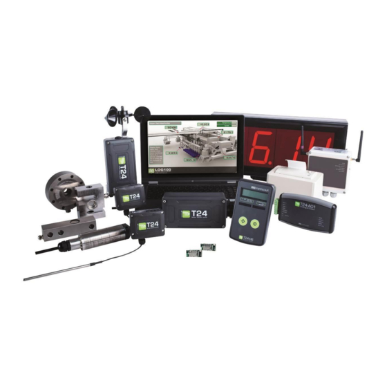
The T24 Telemetry range of products provide remote measurement of a variety of inputs allowing the results to be relayed to a computer or PLC or to feed the data into other T24 modules that provide their own outputs such as analogue, ASCII serial or LED display for example. -
Page 21: Navigating This Manual
Base Stations T24-BSi T24-BSu T24-BSue T24-BSd Gateways T24-GW1 Sensorspace-GB-A Repeaters T24-AR Receivers T24-HS T24-HA T24-HR T24-AO1 T24-AO1i T24-RM1 T24-SO T24-HLT T24-LD1 T24-PR1 T24-RDC T24-DWS Power Supplies T24-BC1 Antennas T24-ANTA T24-ANTB T24-ANTC T24-ANTD T24-ANTE Mantracourt Electronics Limited T24 Telemetry User Manual... -
Page 22: T24 Telemetry Basic Principles
Transmitters & Receivers Although all of the T24 modules are in fact transceivers and transmit as well as receive, they tend to mainly operate as either a transmitter or receiver so we will choose to describe them as Transmitters and Receivers. -
Page 23: Configuring Multiple Modules To Use The Same Radio Settings
Configuration mode forces the modules to pause in sending their messages and to disable their low power state to enable configuration to take place. This is easily achieved by ‘Pairing’ when using the T24 Toolkit software. Once configuration is complete the modules will resume their ‘normal’ mode operation. -
Page 24: Transmitter Module Sleep Delay Settings
Because you need to know the radio settings configured in a module to be able to configure it, and there are no visible clues to what those settings may be, there is a feature used by T24 modules that enable the radio settings (i.e. -
Page 25: Soft Pairing
Configuring an Attached Base Station Because a base station is attached to your computer when you are using the T24 Toolkit you do not pair to it the same way as with other T24 modules. To configure the base station using the Toolkit hold the shift key and click... -
Page 26: Bandwidth
There can also be interference from other sources that can delay module transmissions. Because of the transmission rate flexibility of the T24 modules there could be a few modules transmitting messages at fast rates or many modules transmitting messages at slow rates or any combination of these. -
Page 27: T24 Toolkit
This may use a slider, text box or list to allow your new value to be entered. A base station will also be required to configure the T24 modules. If you have a USB version of the base station (T24-BSu or T24-BSue) then you just need to plug this into a USB socket on your PC. If you are using an alternative base station then please refer to the appropriate section of this manual. -
Page 28: Common Toolkit Pages
Common Toolkit Pages These pages in the T24 Toolkit are applicable to all connected modules. Setup Base Station Communications Select the appropriate interface type for the connected base station. If the base station is connected via a serial port then you will need to know the COM port it is connected to and the baud rate. -
Page 29: Spectrum Analyser
Using this tool may help in detecting noisy areas and allow you to decide on which channels you may want to use. Although 16 channels are shown the T24 modules operate over radio channels 1 to 15. Channel 16 is reserved for pairing negotiation. -
Page 30: Examples
This shows a good RF environment. The Band Noise Floor is low and there are no red traces indicating that there are plenty of signal free gaps to enable T24 to transmit. There is traffic across the whole band with higher signal traffic between channels 11 to 15, but there is nothing that would affect T24 operation. - Page 31 For most channels the minimum signal level is below the CCA threshold, so as long as the T24 signal is strong enough the system will still work. However, note the sloping nature of the red trace.
- Page 32 12 but other channels that were once OK (Having a very low minimum signal level) now have a viewable level of minimum signal noise. A double-click on the planar chart would reset the peak and minimum calculations so the minimum red trace would then follow the more recent higher noise floor. Mantracourt Electronics Limited T24 Telemetry User Manual...
-
Page 33: Channel Monitor
Click a tab to change the radio channel the base station is operating on Clear List Clear all detected messages from the list Wake All Wake all modules on the current radio channel and matching Group Key Mantracourt Electronics Limited T24 Telemetry User Manual... - Page 34 When this button is clicked all modules on the same radio channel and group key will be woken before they are changed to the target radio channel. Mantracourt Electronics Limited T24 Telemetry User Manual...
-
Page 35: Home
Home You now have successful communications with the base station so you can now pair with our remote T24 module or you can select the Spectrum Analyser mode or Data Provider Monitor mode. Connecting to a remote module To connect to a remote module you will pair. This is achieved by power cycling the module. Pairing removes the need to know the radio settings of the module you are connecting to and also ensures that it is in a suitable state for configuration. -
Page 36: Connecting To The Attached Base Station Module
If you cannot get to the power supply of the remote module you can attempt to connect manually using Soft Pairing. Click the ‘Click Here’ link at the bottom of the page and follow the prompts. Mantracourt Electronics Limited T24 Telemetry User Manual... -
Page 37: Information
Extended range radios were introduced to the T24 range in 2015. This indicates that the connected module has an extended range radio fitted. V4.0 radio modules introduce better performance in hostile RF environments. This includes better pairing and reception as well as battery life. -
Page 38: Battery And Radio Levels
Items you can change: Low Battery Level Click this item to set the battery low level. Clicking the Advanced button will give more detailed information on the RSSI and CV levels of the received radio packets. Mantracourt Electronics Limited T24 Telemetry User Manual... -
Page 39: Battery And Radio Levels Advanced
CV is the correlation value and indicates how well the signal can be decoded. This ranges from 55 which is a poor quality signal and 110 which is an excellent signal. Mantracourt Electronics Limited T24 Telemetry User Manual... -
Page 40: Radio Settings
Early versions of T24 modules do not support Group Keys and this option will not be visible in the Toolkit. -
Page 41: Radio Settings Advanced
Apply power to the remote module The Toolkit will remain unchanged and still paired to whatever module or base station it was paired to but the remote module will have changed its radio settings. Mantracourt Electronics Limited T24 Telemetry User Manual... -
Page 42: Save And Restore
Click this button to open a file dialog window to allow you to select a filename and location of a previously saved file to load into the connected module. All configuration information including user calibration data will be overwritten. The file extension is tcf. Mantracourt Electronics Limited T24 Telemetry User Manual... -
Page 43: Transmitter Modules
Transmitter Modules T24 Transmitters are the modules that connect to a sensor or have an input signal applied and periodically transmit messages containing the value read from the sensor or input. T24-ACM-SA, T24-ACMi-SA, T24-ACMm-SA, T24-SAe, T24-SAi Overview The range of SA modules provide measurement from strain gauges and load cells. -
Page 44: Connections
+SIG +EXC The resistance of the strain gauge can be between 85 and 5000 ohms. The T24-SA can support up to four 350 ohm strain gauges bridges attached in parallel (At the expense of reduced battery life). The cable lengths between the T24-SA and the gauges should be kept below three metres and generally as short as possible. -
Page 45: T24-Acm-Sa
Appendix D – Battery Selection Sensor The strain gauge input is connected to the module via a 2 part screw terminal block. Screw Terminal Function +5 V Excitation +Signal -Signal -Excitation Shield Digital Output Mantracourt Electronics Limited T24 Telemetry User Manual... -
Page 46: T24-Acmi-Sa
Appendix D – Battery Selection Sensor The input connections are accessed by lifting the right hand cover plate, this plate incorporates the T24-ACMi Antenna; take extra care when re-assembling that the grey UHF cable is attached to the antenna socket. -
Page 47: T24-Acmm-Sa
Power is supplied by connecting a 3 V supply to the terminals as shown below. There is no reverse polarity protection Connecting T24-BB1 Power to transmitter modules in this enclosure can also be supplied by a T24-BB1 battery box which contains two AA 1.5 V batteries. For battery information please refer to Appendix D –... -
Page 48: Using Completion Resistors
Using Completion Resistors The T24-ACMm has the option for users to add up to three completion resistors, these can be used to enable the T24-ACMm to accept half and quarter bridge strain input when a strain transmitter module is fitted. The three... -
Page 49: Shield Connections (All Enclosures)
This connection must be as short as possible. The T24 Toolkit can be used to chart the signal levels and tests should be undertaken to determine whether there is a better radio signal with or without the shield/chassis connection. -
Page 50: Configuration
The T24 Toolkit provides a means of simple configuration and calibration of the transmitter module along with useful tools to aid integration. Launch the T24 Toolkit software application and pair to this module to enable the connection to the Toolkit to allow configuration to take place. - Page 51 Enter the resistance of the connected strain gauge in Ohms. Usage Per 24 Hour Period Enter the number of hours per 24 hour period that the T24-HS handheld will be turned on and communicating with a transmitter module. Mantracourt Electronics Limited...
-
Page 52: Calibration
For more complex calibrations which include linearisation select three to nine points. Point 1 - 9 For each point enter the engineering unit value that you want the transmitter module to report at the applied input. i.e. 1.67 Mantracourt Electronics Limited T24 Telemetry User Manual... - Page 53 This will take you to a different screen. Advanced Clicking the advanced button will allow you to edit the gains and offsets for each available calibration point. This will take you to a different screen. Mantracourt Electronics Limited T24 Telemetry User Manual...
-
Page 54: Calibration By Certificate
(mV/V shown in this value screenshot) Engineering Units 1 - 9 Enter the required engineering unit output for the specified input value Calibrate Click this button to calculate and update the module calibration Mantracourt Electronics Limited T24 Telemetry User Manual... -
Page 55: Calibration Advanced
When the best point has been found the Gain and Offset values from that point are applied to the mV/V value as follows. Value = (input * Gain) – Offset. Mantracourt Electronics Limited T24 Telemetry User Manual... -
Page 56: Advanced Settings
This can be useful if the module is to be encapsulated or enclosed and enables a second LED to be externally mounted. This is very useful when using a T24-HR roaming handheld as the transmitter module LED will activate while the handheld is in communications with the module. -
Page 57: Enclosure & Mounting
This module uses an integrated chip antenna. See Appendix B – Antennas – Internal Chip Antenna T24-SAe Only the T24-SAe module allows for the fitting of external antennas. The choices are: T24-ANTA PCB Antenna Appendix B – Antennas – T24-ANTA... -
Page 58: Specification
3 weeks Pair AA cells 12 sessions per day of 5 2 years minutes Pair D cells Constantly on 3.5 months Pair D cells 12 sessions per day of 5 5 years minutes Mantracourt Electronics Limited T24 Telemetry User Manual... -
Page 59: Radio Range
Radio Range To determine radio range please refer to Appendix B – Antenna Range Mantracourt Electronics Limited T24 Telemetry User Manual... -
Page 60: T24-Acm-Saf, T24-Acmi-Saf, T24-Acmm-Saf, T24-Safe, T24-Safi
For high speed applications the T24-SAf provides measurements at 2 KHz with 200 packets per second containing 10 x 32 bit values representing nano volts/volt. The T24-SAf will usually be used in conjunction with an analogue output module or for supplying data to a computer via a base station. -
Page 61: Connections
+SIG +EXC The resistance of the strain gauge can be between 85 and 5000 ohms. The T24-SAf can support up to 4 350 ohm strain gauges bridges attached in parallel (At the expense of reduced battery life). The cable lengths between the T24-SA and the gauges should be kept below 3 metres and generally as short as possible. -
Page 62: T24-Acm-Saf
For battery information please refer to Appendix D – Battery Selection Sensor The strain gauge input is connected to the module via a 2 part screw terminal block. Screw Terminal Function +5 V Excitation +Signal -Signal -Excitation Shield Mantracourt Electronics Limited T24 Telemetry User Manual... -
Page 63: T24-Acmi-Saf
Appendix D – Battery Selection Sensor The input connections are accessed by lifting the right hand cover plate, this plate incorporates the T24-ACMi Antenna; take extra care when re-assembling that the grey UHF cable is attached to the antenna socket. -
Page 64: T24-Acmm-Saf
Power is supplied by connecting a 3V supply to the first two screw terminals as shown below. There is no reverse polarity protection. Connecting T24-BB1 Power to transmitter modules in this enclosure can also be supplied by a T24-BB1 battery box which contains two AA 1.5 V batteries. For battery information please refer to Appendix D –... -
Page 65: Using Completion Resistors
Using Completion Resistors The T24-ACMm has the option for users to add up to three completion resistors, these can be used to enable the T24-ACMm to accept half and quarter bridge strain input when a strain transmitter module is fitted. The three... -
Page 66: Shield Connections (All Enclosures)
This connection must be as short as possible. The T24 Toolkit can be used to chart the signal levels and tests should be undertaken to determine whether there is a better radio signal with or without the shield/chassis connection. -
Page 67: Configuration
Configuration The T24 Toolkit provides a means of simple configuration of the transmitter module along with useful tools to aid integration. NOTE: The T24-SAf has a fixed nV/V output and cannot be calibrated! Launch the T24 Toolkit software application and pair to this module to enable the connection to the Toolkit to allow configuration to take place. - Page 68 Enter the resistance of the connected strain gauge in Ohms. Usage Per 24 Hour Period Enter the number of hours per 24 hour period that the T24-SAf will be turned on and communicating. Mantracourt Electronics Limited...
-
Page 69: Zero Settings
Zero Settings Although there is no calibration functionality in the T24-SAf there is the ability to zero the output value. Items you can change: System Zero Value Enter a value which will be subtracted from the current nV/V value. Used to zero the value. -
Page 70: Data Provider Monitor
Data Provider Monitor Because the standard data provider monitor does not decode correctly the multiple data packets from as T24-SAf this special page provides a trend chart and a view of all 10 readings contained in each packet. It also shows a delta value (Max – min) and allows you to log the data to a file. -
Page 71: Advanced Settings
Here you can enter a delay in seconds after which the transmitter module will return to deep sleep if no Keep Awake message is heard from another T24 module such as an analogue output module. The default is 60 seconds. -
Page 72: Enclosure & Mounting
This module uses an integrated chip antenna. See Appendix B – Antennas – Internal Chip Antenna T24-SAfe Only the T24-SAfe module allows for the fitting of external antennas. The choices are: T24-ANTA PCB Antenna Appendix B – Antennas – T24-ANTA... -
Page 73: Specification
Pair D cells Constantly on 5.5 days Pair D cells 12 sessions per day of 5 minutes 4.5 months Radio Range To determine radio range please refer to Appendix B – Antenna Range Mantracourt Electronics Limited T24 Telemetry User Manual... -
Page 74: T24-Acm-Va, T24-Acmi-Va, T24-Acmm-Va, T24-Vae, T24-Vai
T24-ACM-VA, T24-ACMi-VA, T24-ACMm-VA, T24-VAe, T24-VAi Overview The T24-VA module provides wireless voltage measurement for an input range of 0 to 10 volts. Suitable for a range of 0-10 V sensors including pressure, inclinometer, accelerometer, temperature & displacement. Provides 5 V sensor power... -
Page 75: Connections
This module is not reverse polarity protected! The maximum voltage is 3.6V! For battery information please refer to Appendix D – Battery Selection Sensor Voltage input connected as follows: SHLD -Excitation +5V Excitation Mantracourt Electronics Limited T24 Telemetry User Manual... -
Page 76: T24-Acm-Va
For battery information please refer to Appendix D – Battery Selection Sensor The voltage input is connected to the module via a 2 part screw terminal block. Screw Terminal Function +5 V Excitation -Excitation Shield Mantracourt Electronics Limited T24 Telemetry User Manual... -
Page 77: T24-Acmi-Va
Appendix D – Battery Selection Sensor The input connections are accessed by lifting the right hand cover plate, this plate incorporates the T24-ACMi Antenna; take extra care when re-assembling that the grey UHF cable is attached to the antenna socket. -
Page 78: T24-Acmm-Va
Power is supplied by connecting a 3V supply to the There is no reverse polarity protection. Connecting T24-BB1 Power to transmitter modules in this enclosure can also be supplied by a T24-BB1 battery box which contains two AA 1.5 V batteries. For battery information please refer to Appendix D –... -
Page 79: Shield Connections (All Enclosures)
This connection must be as short as possible. The T24 Toolkit can be used to chart the signal levels and tests should be undertaken to determine whether there is a better radio signal with or without the shield/chassis connection. -
Page 80: Configuration
The T24 Toolkit provides a means of simple configuration and calibration of the transmitter module along with useful tools to aid integration. Launch the T24 Toolkit software application and pair to this module to enable the connection to the Toolkit to allow configuration to take place. - Page 81 Enter the resistance of the connected strain gauge in Ohms. Usage Per 24 Hour Period Enter the number of hours per 24 hour period that the T24-HS handheld will be turned on and communicating with a transmitter module. Mantracourt Electronics Limited...
-
Page 82: Calibration
For more complex calibrations which include linearisation select three to nine points. Point 1 - 9 For each point enter the engineering unit value that you want the transmitter module to report at the applied input. i.e. 1.67 Mantracourt Electronics Limited T24 Telemetry User Manual... - Page 83 This will take you to a different screen. Advanced Clicking the advanced button will allow you to edit the gains and offsets for each available calibration point. This will take you to a different screen. Mantracourt Electronics Limited T24 Telemetry User Manual...
-
Page 84: Calibration By Certificate
These modules are factory calibrated where 0% = 0 V and 100% = 10 V Engineering Units 1 - 9 Enter the required engineering unit output for the specified input value Calibrate Click this button to calculate and update the module calibration Mantracourt Electronics Limited T24 Telemetry User Manual... -
Page 85: Calibration Advanced
This leads to a resultant gain and offset which is applied to the mV/V values as follows. Value = (input * Resultant Gain) – Resultant Offset. Mantracourt Electronics Limited T24 Telemetry User Manual... -
Page 86: Advanced Settings
This can be useful if the module is to be encapsulated or enclosed and enables a second LED to be externally mounted. This is very useful when using a T24-HR roaming handheld as the transmitter module LED will activate while the handheld is in communications with the module. -
Page 87: Enclosure & Mounting
This module is fitted inside our medium enclosure. Please see Appendix A – Enclosures & Mounting – ACMi more information. T24-ACMm-VA This module is fitted inside our small enclosure. Please see Appendix A – Enclosures & Mounting – ACMm more information. Mantracourt Electronics Limited T24 Telemetry User Manual... -
Page 88: Antennas
This module uses an integrated chip antenna. See Appendix B – Antennas – Internal Chip Antenna T24-VAe Only the T24-VAe module allows for the fitting of external antennas. The choices are: T24-ANTA PCB Antenna Appendix B – Antennas – T24-ANTA... -
Page 89: Specification
Pair D cells Constantly on 4.5 months Pair D cells 12 sessions per day of 5 minutes > 9 years Radio Range To determine radio range please refer to Appendix B – Antenna Range Mantracourt Electronics Limited T24 Telemetry User Manual... -
Page 90: T24-Acm-Ia, T24-Acmi-Ia, T24-Acmm-Ia, T24-Iae, T24-Iai
T24-ACM-IA, T24-ACMi-IA, T24-ACMm-IA, T24-IAe, T24-IAi Overview The T24-IA module provides wireless current measurement for an input range of 0-20 mA. Suitable for a range of 4-20 mA sensors such as pressure, inclinometer, accelerometer, temperature & displacement. Provides 5 V sensor power... -
Page 91: Connections
5 Vdc to 18 Vdc source. In both cases you need to fit the JP1 power jumper to supply power to the transmitter module. When powered from the external DC source the LED will illuminate. Mantracourt Electronics Limited T24 Telemetry User Manual... -
Page 92: Sensor
For battery information please refer to Appendix D – Battery Selection Sensor The current input is connected to the module via a 2 part screw terminal block. Screw Terminal Function +5 V Excitation -Excitation Shield Mantracourt Electronics Limited T24 Telemetry User Manual... -
Page 93: T24-Acmi-Ia
Appendix D – Battery Selection Sensor The input connections are accessed by lifting the right hand cover plate, this plate incorporates the T24-ACMi Antenna; take extra care when re-assembling that the grey UHF cable is attached to the antenna socket. -
Page 94: T24-Acmm-Ia
Power is supplied by connecting a 3V supply to the There is no reverse polarity protection. Connecting T24-BB1 Power to transmitter modules in this enclosure can also be supplied by a T24-BB1 battery box which contains two AA 1.5 V batteries. For battery information please refer to Appendix D –... -
Page 95: Shield Connections (All Enclosures)
This connection must be as short as possible. The T24 Toolkit can be used to chart the signal levels and tests should be undertaken to determine whether there is a better radio signal with or without the shield/chassis connection. -
Page 96: Configuration
The T24 Toolkit provides a means of simple configuration and calibration of the transmitter module along with useful tools to aid integration. Launch the T24 Toolkit software application and pair to this module to enable the connection to the Toolkit to allow configuration to take place. - Page 97 Enter the resistance of the connected strain gauge in Ohms. Usage Per 24 Hour Period Enter the number of hours per 24 hour period that the T24-HS handheld will be turned on and communicating with a transmitter module. Mantracourt Electronics Limited...
-
Page 98: Calibration
For more complex calibrations which include linearisation select three to nine points. Point 1 - 9 For each point enter the engineering unit value that you want the transmitter module to report at the applied input. i.e. 1.67 Mantracourt Electronics Limited T24 Telemetry User Manual... - Page 99 This will take you to a different screen. Advanced Clicking the advanced button will allow you to edit the gains and offsets for each available calibration point. This will take you to a different screen. Mantracourt Electronics Limited T24 Telemetry User Manual...
-
Page 100: Calibration By Certificate
These modules are factory calibrated where 0% = 4 mA and 100% = 20 Engineering Units 1 - 9 Enter the required engineering unit output for the specified input value Calibrate Click this button to calculate and update the module calibration Mantracourt Electronics Limited T24 Telemetry User Manual... -
Page 101: Calibration Advanced
This leads to a resultant gain and offset which is applied to the mV/V values as follows. Value = (input * Resultant Gain) – Resultant Offset. Mantracourt Electronics Limited T24 Telemetry User Manual... -
Page 102: Advanced Settings
This can be useful if the module is to be encapsulated or enclosed and enables a second LED to be externally mounted. This is very useful when using a T24-HR roaming handheld as the transmitter module LED will activate while the handheld is in communications with the module. -
Page 103: Enclosure & Mounting
This module is fitted inside our medium enclosure. Please see Appendix A – Enclosures & Mounting – ACMi more information. T24-ACMm-IA This module is fitted inside our small enclosure. Please see Appendix A – Enclosures & Mounting – ACMm more information. Mantracourt Electronics Limited T24 Telemetry User Manual... -
Page 104: Antennas
This module uses an integrated chip antenna. See Appendix B – Antennas – Internal Chip Antenna T24-IAe Only the T24-IAe module allows for the fitting of external antennas. The choices are: T24-ANTA PCB Antenna Appendix B – Antennas – T24-ANTA... -
Page 105: Specification
Pair D cells Constantly on 4.5 months Pair D cells 12 sessions per day of 5 minutes > 9 years Radio Range To determine radio range please refer to Appendix B – Antenna Range Mantracourt Electronics Limited T24 Telemetry User Manual... -
Page 106: T24-Acm-Ta, T24-Acmi-Ta, T24-Acmm-Ta, T24-Tae, T24-Tai
T24-ACM-TA, T24-ACMi-TA, T24-ACMm-TA, T24-TAe, T24-TAi Overview The T24-TA temperature sensor transmitter is a high performance module designed for the collection and processing of temperature measurements. The wireless sensor transmitter requires an external platinum temperature sensor (Pt100 type 385). Order Codes... -
Page 107: Connections
This configuration allows use of bridge so that the resistance is cancelled out, so long 100 meters of cable. as the two lead resistances are accurately the same. This configuration allows up to 600 metres of cable. Mantracourt Electronics Limited T24 Telemetry User Manual... -
Page 108: Wire
For battery information please refer to Appendix D – Battery Selection Sensor The temperature sensor input is connected to the module via a 2 part screw terminal block. Screw Terminal Function +Drive +Sense -Sense -Drive Shield Mantracourt Electronics Limited T24 Telemetry User Manual... -
Page 109: T24-Acmi-Ta
Appendix D – Battery Selection Sensor The input connections are accessed by lifting the right hand cover plate, this plate incorporates the T24-ACMi Antenna; take extra care when re-assembling that the grey UHF cable is attached to the antenna socket. -
Page 110: Connecting T24-Bb1
Connecting T24-BB1 Power to transmitter modules in this enclosure can also be supplied by a T24-BB1 battery box which contains two AA 1.5 V batteries. For battery information please refer to Appendix D – Battery Selection Sensor Screw Terminal Function... -
Page 111: Shield Connections (All Enclosures)
This connection must be as short as possible. The T24 Toolkit can be used to chart the signal levels and tests should be undertaken to determine whether there is a better radio signal with or without the shield/chassis connection. -
Page 112: Configuration
The T24 Toolkit provides a means of simple configuration and calibration of the transmitter module along with useful tools to aid integration. Launch the T24 Toolkit software application and pair to this module to enable the connection to the Toolkit to allow configuration to take place. - Page 113 Enter the resistance of the connected strain gauge in Ohms. Usage Per 24 Hour Period Enter the number of hours per 24 hour period that the T24-HS handheld will be turned on and communicating with a transmitter module. Mantracourt Electronics Limited...
-
Page 114: Calibration
The value you enter here will be subtracted from the measured temperature to create the transmitted temperature. The offset is entered in the same engineering units as selected above. Mantracourt Electronics Limited T24 Telemetry User Manual... -
Page 115: Advanced Settings
This can be useful if the module is to be encapsulated or enclosed and enables a second LED to be externally mounted. This is very useful when using a T24-HR roaming handheld as the transmitter module LED will activate while the handheld is in communications with the module. -
Page 116: Enclosure & Mounting
This module uses an integrated chip antenna. See Appendix B – Antennas – Internal Chip Antenna T24-TAe Only the T24-TAe module allows for the fitting of external antennas. The choices are: T24-ANTA PCB Antenna Appendix B – Antennas – T24-ANTA... -
Page 117: Specification
Pair D cells Constantly on 4.5 months Pair D cells 12 sessions per day of 5 minutes > 9 years Radio Range To determine radio range please refer to Appendix B – Antenna Range Mantracourt Electronics Limited T24 Telemetry User Manual... -
Page 118: T24-Acm-Ra, T24-Acmi-Ra, T24-Acmm-Ra, T24-Rae, T24Rai
T24-ACM-RA, T24-ACMi-RA, T24-ACMm-RA, T24-RAe, T24RAi Overview The T24-RA is a remote transmitter module for the collection and processing of potentiometer resistance measurements. The module measures the resistance and periodically transmits it. Between transmissions the module is optionally in a power saving sleep mode to conserve batteries... -
Page 119: Connections
5 Vdc to 18 Vdc source. In both cases you need to fit the JP1 power jumper to supply power to the transmitter module. When powered from the external DC source the LED will illuminate. Mantracourt Electronics Limited T24 Telemetry User Manual... -
Page 120: Sensor
For battery information please refer to Appendix D – Battery Selection Sensor The resistance input is connected to the module via a 2 part screw terminal block. Screw Terminal Function +2V5 Excitation +Input Not Connected -Excitation Shield Mantracourt Electronics Limited T24 Telemetry User Manual... -
Page 121: T24-Acmi-Ra
Appendix D – Battery Selection Sensor The input connections are accessed by lifting the right hand cover plate, this plate incorporates the T24-ACMi Antenna; take extra care when re-assembling that the grey UHF cable is attached to the antenna socket. -
Page 122: T24-Acmm-Ra
Power is supplied by connecting a 3 V supply to the There is no reverse polarity protection. Connecting T24-BB1 Power to transmitter modules in this enclosure can also be supplied by a T24-BB1 battery box which contains two AA 1.5 V batteries. For battery information please refer to Appendix D –... -
Page 123: Shield Connections (All Enclosures)
This connection must be as short as possible. The T24 Toolkit can be used to chart the signal levels and tests should be undertaken to determine whether there is a better radio signal with or without the shield/chassis connection. -
Page 124: Configuration
The T24 Toolkit provides a means of simple configuration and calibration of the transmitter module along with useful tools to aid integration. Launch the T24 Toolkit software application and pair to this module to enable the connection to the Toolkit to allow configuration to take place. - Page 125 Although the Impedance will vary an estimate of the average sensor impedance will provide a good indication of battery life. Usage Per 24 Hour Period Enter the number of hours per 24 hour period that the T24-HS handheld will be turned on and communicating with a transmitter module. Mantracourt Electronics Limited...
-
Page 126: Input / Output Configuration
For more complex calibrations which include linearisation select three to nine points. Point 1 - 9 For each point enter the engineering unit value that you want the transmitter module to report at the applied input. i.e. 1.67 Mantracourt Electronics Limited T24 Telemetry User Manual... - Page 127 This will take you to a different screen. Advanced Clicking the advanced button will allow you to edit the gains and offsets for each available calibration point. This will take you to a different screen. Mantracourt Electronics Limited T24 Telemetry User Manual...
-
Page 128: Calibration By Certificate
( shown in this screenshot) value Engineering Units 1 - 9 Enter the required engineering unit output for the specified input value Calibrate Click this button to calculate and update the module calibration Mantracourt Electronics Limited T24 Telemetry User Manual... -
Page 129: Calibration Advanced
This parameter stops the unit reporting values outside the viable input range. System Zero You can set the system zero value here or set it to zero to remove the system zero effect. Mantracourt Electronics Limited T24 Telemetry User Manual... - Page 130 This leads to a resultant gain and offset which is applied to the mV/V values as follows. Value = (input * Resultant Gain) – Resultant Offset. Mantracourt Electronics Limited T24 Telemetry User Manual...
-
Page 131: Advanced Settings
This can be useful if the module is to be encapsulated or enclosed and enables a second LED to be externally mounted. This is very useful when using a T24-HR roaming handheld as the transmitter module LED will activate while the handheld is in communications with the module. -
Page 132: Enclosure & Mounting
This module is fitted inside our medium enclosure. Please see Appendix A – Enclosures & Mounting – ACMi more information. T24-ACMm-RA This module is fitted inside our small enclosure. Please see Appendix A – Enclosures & Mounting – ACMm more information. Mantracourt Electronics Limited T24 Telemetry User Manual... -
Page 133: Antennas
This module uses an integrated chip antenna. See Appendix B – Antennas – Internal Chip Antenna T24-RAe Only the T24-RAe module allows for the fitting of external antennas. The choices are: T24-ANTA PCB Antenna Appendix B – Antennas – T24-ANTA... -
Page 134: Specification
Pair D cells Constantly on 4.5 months Pair D cells 12 sessions per day of 5 minutes > 9 years Radio Range To determine radio range please refer to Appendix B – Antenna Range Mantracourt Electronics Limited T24 Telemetry User Manual... -
Page 135: T24-Acm-Pa, T24-Acmi-Pa, T24-Acmm-Pa, T24-Pae, T24-Pai
Appendix E – Legacy products Overview The T24-PA is a remote transmitter module for the collection and processing of pulse related measurements. This includes measuring the period between pulses to provide outputs in Hz, RPM and Time as well as actual pulse counting. -
Page 136: Connections
When in Quadrature output mode the ‘Input A’ and ‘Input B’ inputs are connected to the Quadrature outputs A and B respectively. The T24-PA can also be used with a repetitive sine, square or pulse wave signal source such as a signal generator or RPM sensor. The amplitude should be between 1.2 V and 12 V peak. -
Page 137: Voltage Source
Input A Excitation Onboard resistor configured for pull up and suitable excitation voltage selected PNP Open Collector Powered Sensor SHIELD Input A Excitation Onboard resistor configured for pull down and suitable excitation voltage selected Mantracourt Electronics Limited T24 Telemetry User Manual... -
Page 138: Quadrature Sensor
OUT B (2) Input A OUT A (1) Excitation Onboard resistor configured to suit sensor and suitable excitation voltage selected The quadrature inputs A and B determine direction based on the following table. Mantracourt Electronics Limited T24 Telemetry User Manual... -
Page 139: T24-Acm-Pa
The pulse input is connected to the module via a 2 part screw terminal block. Screw Terminal Function +Excitation Input A Input B - Excitation (GND) Shield Reset Count T24-PAe, T24-PAi section above for wiring options. Mantracourt Electronics Limited T24 Telemetry User Manual... -
Page 140: T24-Acmi-Pa
Appendix D – Battery Selection Sensor The input connections are accessed by lifting the right hand cover plate, this plate incorporates the T24-ACMi Antenna; take extra care when re-assembling that the grey UHF cable is attached to the antenna socket. -
Page 141: T24-Acmm-Pa
Power is supplied by connecting a 3V supply to the pins shown below. There is no reverse polarity protection. Connecting T24-BB1 Power to transmitter modules in this enclosure can also be supplied by a T24-BB1 battery box which contains two AA 1.5 V batteries. For battery information please refer to Appendix D –... -
Page 142: Shield Connections (All Enclosures)
This connection must be as short as possible. The T24 Toolkit can be used to chart the signal levels and tests should be undertaken to determine whether there is a better radio signal with or without the shield/chassis connection. -
Page 143: Configuration
The T24 Toolkit provides a means of simple configuration and calibration of the transmitter module along with useful tools to aid integration. Launch the T24 Toolkit software application and pair to this module to enable the connection to the Toolkit to allow configuration to take place. - Page 144 This is the current drawn by any sensor attached to the user selectable excitation on board power supply. Usage Per 24 Hour Period Enter the number of hours per 24 hour period that the module will be turned on and transmitting. Mantracourt Electronics Limited T24 Telemetry User Manual...
-
Page 145: Input / Output Configuration
+V the output will be 0. This can be inverted by setting a Gain = -1 and Offset = -1 in Advanced Scaling page. Mark (Space) – Gives the percentage of Mark over Space for inputs on ‘Input A’. Mantracourt Electronics Limited T24 Telemetry User Manual... - Page 146 By entering the minimum frequency or RPM measurement required, the module can calculate the most effective form of power saving to apply. Not available in Counter, Quadrature and Digital State output modes. Advanced Button Click to show the advanced page described below. Mantracourt Electronics Limited T24 Telemetry User Manual...
-
Page 147: Advanced I/O
If using the counter output the data tag specified in this field will cause the counter in the T24-PA to reset to zero whenever a data packet with this data tag is received. Data providers can be produced by other transmitter modules, T24- HA or custom software. -
Page 148: Advanced Settings
This can be useful if the module is to be encapsulated or enclosed and enables a second LED to be externally mounted. This is very useful when using a T24-HR roaming handheld as the transmitter module LED will activate while the handheld is in communications with the module. -
Page 149: Enclosure & Mounting
This module is fitted inside our medium enclosure. Please see Appendix A – Enclosures & Mounting – ACMi more information. T24-ACMm-PA This module is fitted inside our small enclosure. Please see Appendix A – Enclosures & Mounting – ACMm more information. Mantracourt Electronics Limited T24 Telemetry User Manual... -
Page 150: Antennas
This module uses an integrated chip antenna. See Appendix B – Antennas – Internal Chip Antenna T24-PAe Only the T24-PAe module allows for the fitting of external antennas. The choices are: T24-ANTA PCB Antenna Appendix B – Antennas – T24-ANTA... -
Page 151: Specification
Pair D cells Constantly on 6 months Pair D cells 12 sessions per day of 5 minutes > 6 years Radio Range To determine radio range please refer to Appendix B – Antenna Range Mantracourt Electronics Limited T24 Telemetry User Manual... -
Page 152: T24-Wss, T24-Wssp
Mantracourt’s PowerPack and SolarPanel (PP1 & SP1) offers an ideal solution. The T24 WSSp is battery powered only and is designed for mounting to moving booms using the pivot bar mechanism. Mantracourt Electronics Limited T24 Telemetry User Manual... -
Page 153: Order Codes
D cell alkaline batteries. Also has ability to be powered cell alkaline batteries. Designed for pivot mounting to from external supply voltage. moving booms. For clamp mounting to 50 mm scaffold pole. Mantracourt Electronics Limited T24 Telemetry User Manual... -
Page 154: Connections
The T24 Toolkit provides a means of simple configuration and calibration of the transmitter module along with useful tools to aid integration. Launch the T24 Toolkit software application and pair to this module to enable the connection to the Toolkit to allow configuration to take place. -
Page 155: Data Rates And Quality
So setting this to zero would always transmit the average wind speed between transmissions. Mantracourt Electronics Limited T24 Telemetry User Manual... - Page 156 Temperature and internal resistance of the battery are not taken into account in the guide. Usage Per 24 Hour Period Enter the number of hours per 24 hour period that the module will be turned on and transmitting. Mantracourt Electronics Limited T24 Telemetry User Manual...
-
Page 157: Units
Output Value is the live value of the current wind speed in the units selected above. Items you can change: Output Units Simply select the required output units from the drop down list. The T24-WSS can provide wind speed in: Description... -
Page 158: Advanced Settings
4 characters in their ID (1 in 65,535 chances) you may want to change the Data Tag of one of the modules and perform pairing again with the T24-HS handheld. Average Wind Speed is transmitted using the defined Data tag. -
Page 159: Enclosure & Mounting
Enclosure & Mounting T24-WSS The T24-WSS is designed to be attached to the top of a 50 mm scaffold pole or equivalent using the fitted clamp. Mantracourt Electronics Limited T24 Telemetry User Manual... -
Page 160: T24-Wssp
T24-WSSp The T24-WSS is designed to be attached to a moving boom and uses a pivot design to ensure that the sensor remains upright regardless of the angle of the boom. The pivot bar is threaded for M8. Boom Mounting Remove the mounting pivot bar from the wind speed sensor. - Page 161 Note that angle iron can be used to extend the mounting position to be clear of the top of the boom. Re-fit the wind speed sensor to the bar, add the M8 washer and fit the split pin/cotter pin. Mantracourt Electronics Limited T24 Telemetry User Manual...
-
Page 162: Antennas
Antennas These modules have the antenna already fitted inside the enclosure so there are no specific mounting requirements. Mantracourt Electronics Limited T24 Telemetry User Manual... -
Page 163: Specification
Pair D cells Constantly on 1 year Pair D cells 12 sessions per day of 10 minutes 6 years Radio Range To determine radio range please refer to Appendix B – Antenna Range Mantracourt Electronics Limited T24 Telemetry User Manual... -
Page 164: T24-Lt1
The T24-LT1 transmitter module provides OEM’s with a versatile wireless Running Line Tensiometer which when connected to an appropriate piece of hardware gives cable tension, payout and speed. The T24-LT1 connects to a load pin and quadrature sensor. The quadrature sensor is usually constructed from reed switches and magnets arranged to give overlapping pulses so that both count and direction can be determined. -
Page 165: Connections
+SIG +EXC The resistance of the strain gauge can be between 85 and 5000 ohms. The T24-LT1 can support up to four 350 ohm strain gauges bridges attached in parallel (At the expense of reduced battery life). The cable lengths between the T24-LT1 and the gauges should be kept below three metres and generally as short as possible. -
Page 166: Quadrature Inputs
The quadrature input sensors A and B should be mounted so that the activation zones (Whether optical or magnetic etc) cover both A and B inputs simultaneously as rotation occurs. The inputs then determine direction based on the following table. Mantracourt Electronics Limited T24 Telemetry User Manual... -
Page 167: Shield Connections (All Enclosures)
This connection must be as short as possible. The T24 Toolkit can be used to chart the signal levels and tests should be undertaken to determine whether there is a better radio signal with or without the shield/chassis connection. -
Page 168: Configuration
The T24 Toolkit provides a means of simple configuration and calibration of the transmitter module along with useful tools to aid integration. Launch the T24 Toolkit software application and pair to this module to enable the connection to the Toolkit to allow configuration to take place. - Page 169 Ohms. Usage Per 24 Hour Period Enter the number of hours per 24 hour period that the T24-HLT handheld (Or other sleep/wake controlling receiver) will be turned on and communicating with a transmitter module.
-
Page 170: Calibration (Load)
For more complex calibrations which include linearisation select three to nine points. Point 1 - 9 For each point enter the engineering unit value that you want the transmitter module to report at the applied input. i.e. 1.67 Mantracourt Electronics Limited T24 Telemetry User Manual... - Page 171 This will take you to a different screen. Advanced Clicking the advanced button will allow you to edit the gains and offsets for each available calibration point. This will take you to a different screen. Mantracourt Electronics Limited T24 Telemetry User Manual...
-
Page 172: Calibration By Certificate (Load)
(mV/V shown in this value screenshot) Engineering Units 1 - 9 Enter the required engineering unit output for the specified input value Calibrate Click this button to calculate and update the module calibration Mantracourt Electronics Limited T24 Telemetry User Manual... -
Page 173: Calibration Advanced (Load)
When the best point has been found the Gain and Offset values from that point are applied to the mV/V value as follows. Value = (input * Gain) – Offset. Mantracourt Electronics Limited T24 Telemetry User Manual... -
Page 174: Calibration (Payout & Speed)
This shows the calibrated final Speed value that will be transmitted. The Data Tag used to transmit this value is shown in the title. Auto Calibration Actuators Enter the number of actuators situated around the wheel. An actuator is defined Mantracourt Electronics Limited T24 Telemetry User Manual... - Page 175 Enter the wheel diameter. Note that this dimension needs to take into account where the cable sits on the wheel and is unlikely to be the external diameter. Calibrate Button Click this button to calculate and update the module calibration. Mantracourt Electronics Limited T24 Telemetry User Manual...
-
Page 176: Advanced Settings
Items you can change: Sleep Delay Here you can enter a delay in seconds after which the transmitter module will return to deep sleep if no Keep Awake message is heard from the T24-HS handheld. The default is 60 seconds. Data Tag The data transmitted by the module is identified by a Data Tag. -
Page 177: Enclosure & Mounting
Antennas The choices are: T24-ANTA PCB Antenna Appendix B – Antennas – T24-ANTA T24-ANTB Dipole Antenna Appendix B – Antennas – T24-ANTB T24-ANTC Dipole Antenna Swivel Appendix B –... -
Page 178: Specification
Pair AA cells Constantly on 12 Days Pair AA cells 12 sessions per day of 5 290 Days minutes Radio Range To determine radio range please refer to Appendix B – Antenna Range Mantracourt Electronics Limited T24 Telemetry User Manual... -
Page 179: Receiver Modules
T24-HS Overview The T24-HS is a simple handheld display. This allows wireless remote viewing of various remote inputs such as strain gauge or voltage etc. using 2.4GHz radio. The remote transmitter module measures its input value (strain gauge, voltage, current etc.) and periodically transmits it. -
Page 180: Quick Start
Ensure that transmitter module is not powered. You need to turn on the T24-HS in pairing mode. To do this you start with it turned off. Whilst pressing the power key press the tare key as well until 'PAIRING' is seen on the display. The keys can now be released. -
Page 181: Operation
Modes Pairing When you want to use the T24-HS with a different transmitter module you use pairing. (Ensure that the transmitter module is unpowered for at least 10 seconds.) Press and hold the Power key then while still holding down the power key press and hold the Tare key. - Page 182 There may be open or short circuits. Rather than display a misleading reading this error is displayed instead. Only certain transmitter modules support this error such as the T24-SA. Overload The overload limit set by the user has been exceeded.
-
Page 183: Configuration
Configuration The T24 Toolkit provides a means of simple configuration of the handheld module along with useful tools to aid integration. Launch the T24 Toolkit software application and pair to this module to enable the connection to the Toolkit to allow configuration to take place. -
Page 184: Zero Settings
Here you can adjust settings that affect the display of zero. Items you can change: Power On Auto Zero Here you can determine whether the T24-HS performs automatic zero when it is powered on. Enter zero to disable this function. - Page 185 (By setting the display resolution you may hide this difference) by setting a small value here such as 0.2kg the display will show a stable zero while actual weight is fluctuating less than ± 0.2kg. Mantracourt Electronics Limited T24 Telemetry User Manual...
-
Page 186: Display Format
‘--------‘ is displayed on the LCD. Should be at least 3 times the interval between the data being transmitted by the transmitter module. Advanced This opens the advanced page where you can scale the displayed data. Mantracourt Electronics Limited T24 Telemetry User Manual... -
Page 187: Display Format Advanced Settings
Here you can adjust the display update rate and also scale the displayed data. This may be used, for example, to convert the data from a T24-SA calibrated in kg so that the handheld display shows lb. Items you can change: Display Update Rate Enter the interval in milliseconds between display updates. -
Page 188: Advanced Settings
Indicates the ID of the currently paired transmitter. Enter the ID of the desired transmitter. Note that the transmitter must be set to the same radio channel and group key as the hand held module. Mantracourt Electronics Limited T24 Telemetry User Manual... - Page 189 You would need to refer to the programmers manual of the appropriate transmitter module to work out where to extract data from and what type. The default of INT32 with a Start Byte of zero is the default which will be correct for a T24-SAF module. Mantracourt Electronics Limited...
-
Page 190: Enclosure & Mounting
Enclosure & Mounting Appendix A – Handheld Style section for more information. Antennas These modules have the antenna already fitted inside the enclosure so there are no specific mounting requirements. Mantracourt Electronics Limited T24 Telemetry User Manual... -
Page 191: Specification
IP67 Operating Temperature Range Storage Temperature Humidity Physical Hand Held Dimensions 90 mm x 152 mm x 34 mm Radio Range To determine radio range please refer to Appendix B – Antenna Range Mantracourt Electronics Limited T24 Telemetry User Manual... -
Page 192: T24-Ha
This is the default mode in which multiple transmitter modules are used to create a result which is displayed. Currently the T24-HA only provides a sum of the remote modules but this function may be added to in future versions. Although the handheld usually shows the result (sum) there is an option of viewing the discrete values that make up the result. -
Page 193: Operation
Power Key - Press and hold the power key until the display shows BUSY then release the key. Can also be used, by giving a quick press, to reset the Auto-Sleep delay. Mantracourt Electronics Limited T24 Telemetry User Manual... -
Page 194: Result Mode
). This can be used to trigger external actions such as a printout or a relay operation. This would require suitable relay or printer T24 modules. Power Key - Toggles between on and off. Hold for 2 seconds to activate. - Page 195 This transmits a Data Provider packet marked with a Data Tag held in F1DataTag and can also contain data as defined by F1Data. This can be used to trigger external actions such as a printout. Power Key - Toggles between on and off. Hold for 2 seconds to activate. Mantracourt Electronics Limited T24 Telemetry User Manual...
-
Page 196: All Modes
There may be open or short circuits. Rather than display a misleading reading this error is displayed instead. Only certain transmitter modules support this error such as the T24-SA. Overload The overload limit set by the user has been exceeded. -
Page 197: Configuration
Configuration The T24 Toolkit provides a means of simple configuration of the handheld module along with useful tools to aid integration. Launch the T24 Toolkit software application and pair to this module to enable the connection to the Toolkit to allow configuration to take place. - Page 198 See Prompts F1 Data Tag The F1 key can be used to trigger other modules such as a T24-SO module to provide printer services etc. This key will generate a Data Provider message which other modules can use.
-
Page 199: Prompts
7 segment LCD display is very limited in how it can represent letters. Some letters cannot be displayed. These include K, M, W, X Prompt for result Enter the prompt to display before the total result is displayed. Mantracourt Electronics Limited T24 Telemetry User Manual... -
Page 200: Zero Settings
Here you can adjust settings that affect the display of zero. Items you can change: Power On Auto Zero Here you can determine whether the T24-HA performs automatic zero when it is powered on. Enter zero to disable this function. - Page 201 This section allows the user to apply or remove a system zero. This will require that the transmitter modules are configured and attached to the handheld and the entire system is ready for zeroing. Mantracourt Electronics Limited T24 Telemetry User Manual...
-
Page 202: Zero Settings Advanced
The same handheld is used with a truck that picks up different trailers and is required to display the sum of 4 strain gauges connected to each trailer (Using T24-SAs). Because each trailer will have a different system zero requirement you would add a further module to each trailer set to transmit the system zero value. -
Page 203: Display Format
You can enter a limit here above which Overload will be shown on the display instead of the actual value. Enter zero to disable this feature. Advanced This opens the advanced page where you can scale the displayed data. Mantracourt Electronics Limited T24 Telemetry User Manual... - Page 204 The F1 key will be disabled while the reading is in motion. Motion Time Enter a time in seconds within which the displayed value must not change more than the Motion Band amount set above. Mantracourt Electronics Limited T24 Telemetry User Manual...
-
Page 205: Display Format Advanced Settings
Here you can adjust the display update rate and also scale the displayed data. This may be used, for example, to convert the data from a T24-SA calibrated in kg so that the handheld display shows lb. Items you can change: Display Update Rate Enter the interval in milliseconds between display updates. -
Page 206: Advanced Settings
Used when in Result Mode and the Next key has been enabled to allow viewing of discrete inputs. Enter a time in seconds that the individual item value will be displayed for before the display is automatically switched back to showing the result. Mantracourt Electronics Limited T24 Telemetry User Manual... - Page 207 The time you enter here in milliseconds is the time that this message will be displayed before the actual value is shown. Newer versions of the handheld allow the user to define these message prompts. See Prompts Mantracourt Electronics Limited T24 Telemetry User Manual...
-
Page 208: Enclosure & Mounting
Enclosure & Mounting Appendix A – Handheld Style section for more information. Antennas These modules have the antenna already fitted inside the enclosure so there are no specific mounting requirements. Mantracourt Electronics Limited T24 Telemetry User Manual... -
Page 209: Specification
IP67 Operating Temperature Range Storage Temperature Humidity Physical Hand Held Dimensions 90 mm x 152 mm x 34 mm Radio Range To determine radio range please refer to Appendix B – Antenna Range Mantracourt Electronics Limited T24 Telemetry User Manual... -
Page 210: T24-Hr
T24-HR Overview The T24-HR is a roaming handheld that can be used to view the reading supplied by an unlimited number of transmitter modules. The transmitter module Data Tags or IDs do not need to be known beforehand. The handheld will automatically wake any module on the same channel and group key. -
Page 211: Operation
If you need to change the channel of the transmitter module you will need to use the T24 Toolkit software or see Pairing later in the manual. -
Page 212: Errors
Overload The overload limit set by the user has been exceeded. Special Modes T24-HR label actually has 6 keys but only 2 are marked. The following modes require some of the unmarked keys. Pair The handheld has the ability to configure a transmitter module to match the handheld’s own radio channel and group key settings. -
Page 213: Transmitter Module Configuration
1 every 30 seconds. Just remember to set the Timeout of the handheld to at least 3 times this period. (i.e. 91 seconds in the case of 30 second transmission interval). The handheld will wake any sleeping module if it is on the same channel and has the same group key. Mantracourt Electronics Limited T24 Telemetry User Manual... -
Page 214: Configuration
Configuration The T24 Toolkit provides a means of simple configuration of the handheld module along with useful tools to aid integration. Launch the T24 Toolkit software application and pair to this module to enable the connection to the Toolkit to allow configuration to take place. - Page 215 LCD. Should be at least 3 times the interval between the messages being sent by the transmitter module. Advanced This opens the advanced page where you can scale the displayed data. Mantracourt Electronics Limited T24 Telemetry User Manual...
-
Page 216: Display Format Advanced Settings
Here you can adjust the display update rate and also scale the displayed data. This may be used, for example, to convert the data from a T24-SA calibrated in kg so that the handheld display shows lb. Items you can change: Display Update Rate Enter the interval in milliseconds between display updates. -
Page 217: Settings
Enter a value in engineering units which represents a band (+/-) about zero within which zero will be displayed. As soon as the value is outside this band the real value will be shown. (Only available in version 1.01 onwards) Mantracourt Electronics Limited T24 Telemetry User Manual... -
Page 218: Example Installation Scenarios
On the T24-HR setting the List Size to 6 allows the operator a fast responding Next key that cycles through the closest 6 modules to allow the operator to note any out of limit readings. The operator checks the Data Tag displayed on the handheld as the Next key is pressed against the Data Tag painted on the modules affixed to the bridge. -
Page 219: Enclosure & Mounting
Enclosure & Mounting Appendix A – Handheld Style section for more information. Antennas These modules have the antenna already fitted inside the enclosure so there are no specific mounting requirements. Mantracourt Electronics Limited T24 Telemetry User Manual... -
Page 220: Specification
IP67 Operating Temperature Range Storage Temperature Humidity Physical Hand Held Dimensions 90 mm x 152 mm x 34 mm Radio Range To determine radio range please refer to Appendix B – Antenna Range Mantracourt Electronics Limited T24 Telemetry User Manual... -
Page 221: T24-Ao1, T24-Ao1I
The analogue output is updated at a rate configured by the transmitter module’s ‘TXInterval’. LEDs and, in the case of the T24-AO1i, open collector outputs, provide indication of the state of the radio link, remote battery life and remote status. -
Page 222: Connections
Connections Power You will need to connect a power supply to the T24-AO1 for it to operate and to enable configuration using a base station and the T24 Toolkit software. Power is supplied via the screw terminals and can be in the range of 9 Vdc to 36 Vdc. -
Page 223: Connections And Indicators
To configure the required output range the DIP switches (SW2) require setting as follows. To access the DIP switches you will need to remove the cover from the case. SW2 Switch Settings Range 0-10 V +/-10 V 0-5 V +/-5 V 0-20 mA Sink Mantracourt Electronics Limited T24 Telemetry User Manual... -
Page 224: Led Indicators
50Hz the LED will appear constantly illuminated. Timeout Lost communications with the remote module. Error Remote module is reporting an error. Batt Low Remote module is reporting a low battery. Mantracourt Electronics Limited T24 Telemetry User Manual... -
Page 225: Configuration
To associate the T24-AO1 with a transmitter module you just need to let the T24-AO1 know the Data Tag of the data to use. This can be done manually using the T24 Toolkit (See below) or this can be achieved using the Pair button of the T24-AO1. -
Page 226: Input / Output
Output 0-10 V +/-10 V -10 V 0-5 V +/-5 V -5 V 0-20 mA Sink 0 mA 0-20 mA Source 0 mA 4-20 mA Sink 4 mA 4-20 mA Source 4 mA Mantracourt Electronics Limited T24 Telemetry User Manual... - Page 227 2KHz. This has the effect of delaying the output (latency) by the interval between values being delivered to the input. i.e. The T24-AO1 must receive an input value then start to ramp up to it from the previous input value.
-
Page 228: Alarm Settings
Remote Batt Action When the transmitter module reports a low battery this action will occur. See the Output Actions section for the available actions and the effect of these choices on the different output ranges. Mantracourt Electronics Limited T24 Telemetry User Manual... - Page 229 Minimum Output * -0.5 -0.3 -5.5 Maximum Output * 22.4 22.4 Half Full Scale Hold Last Output * The values shown here are approximate. Each module will vary depending on tolerances of electronic components. Mantracourt Electronics Limited T24 Telemetry User Manual...
-
Page 230: Zero Settings
Click to use the current input value as the new system zero. Remove System Zero Remove the system zero so that the input value is directly used to determine the analogue output. System Zero Enter the required system zero value. Mantracourt Electronics Limited T24 Telemetry User Manual... -
Page 231: Advanced Settings
Items you can change: Pair Wait Duration Here you can set the duration that the T24-AO1 will wait to achieve successful pairing after the Pair Switch is pressed. The default is 5 seconds. Paired Data Tag This shows the currently paired Data Tag. -
Page 232: Enclosure & Mounting
This module is fitted inside our ACM ABS enclosure. Please see Appendix A – Enclosures & Mounting – ACM more information. Antennas These modules have the antenna already fitted inside the enclosure so there are no specific mounting requirements. Mantracourt Electronics Limited T24 Telemetry User Manual... -
Page 233: Specification
190 X 80 X 55 mm Environmental T24-AO1 IP50 T24-AO1i IP67 Humidity 95%RH (max) Radio Range To determine T24-AO1i radio range please refer to Appendix B – Antenna Range The T24-AO1 has a maximum range of 100m Mantracourt Electronics Limited T24 Telemetry User Manual... -
Page 234: T24-Rm1
The T24-RM1 offers dual power relays capable of mains power switching. These relays can be configured as high, low or window alarms and can be associated with a group of up to 8 T24 transmitter modules per relay. Relays can operate when the sum of the assigned transmitter modules reach a setpoint or when any of the modules reach the setpoint. -
Page 235: Connections
Connections Power You will need to connect power to the T24-RM1 for it to operate. Only power is required to enable configuration using a base station and the appropriate toolkit software. Power is connected to the two part two way screw terminal connector as shown in the diagram below. -
Page 236: Operation
Operation The T24 RM1 can accept 8 T24 data inputs for each of the two relays, the total of the inputs compared to the set point and mode of the relay channel affects whether the relay is energised or not. In addition when considering the use relays attention should be paid as to what state the system will be in when the power is off. -
Page 237: Configuration
The T24 Toolkit provides a means of simple configuration of the module along with useful tools to aid integration. Launch the T24 Toolkit software application and pair to this module to enable the connection to the Toolkit to allow configuration to take place. -
Page 238: Relay Operation Settings
(See diagram on next page) Latching [1-2] Latching locks the state of the relay when it passes the set point. Advanced Button Displays the Relay Settings Advanced page. Mantracourt Electronics Limited T24 Telemetry User Manual... -
Page 239: Operation And Hysteresis Settings
Operation and Hysteresis Settings Relay de-energises when reaching the set point. Mantracourt Electronics Limited T24 Telemetry User Manual... -
Page 240: Relay Settings Advanced
Transmitter modules will be kept awake while this module has power applied. The transmitter modules should have a Sleep Delay set so that after the relay module has been powered down the transmitter modules then return to sleep. Mantracourt Electronics Limited T24 Telemetry User Manual... -
Page 241: Alarm Settings
Alarm Settings This page defines how the individual relays will react to time outs and errors present from any defined T24 module, as well as how Digital inputs 1 and 2 are used. Items you can change: Timeout Enter a time in seconds that if exceeded the T24-RM1 will affect the relay state... -
Page 242: Enclosure & Mounting
This module is fitted inside our ACM ABS enclosure. Please see Appendix A – Enclosures & Mounting – ACM more information. Antennas These modules have the antenna already fitted inside the enclosure so there are no specific mounting requirements. Mantracourt Electronics Limited T24 Telemetry User Manual... -
Page 243: Specification
24VDC 120VAC 1A Operational Temperature Range °C Storage Temperature Range °C Humidity IP Rating IP67 * At 12 Volt nominal Supply Radio Range To determine radio range please refer to Appendix B – Antenna Range Mantracourt Electronics Limited T24 Telemetry User Manual... -
Page 244: T24-So
Overview The T24-SO creates a serial output which can include data from up to 8 modules and optionally sum them. The output is suitable for connecting to a printer, serial display or for feeding directly into a PC, PLC or any module that is capable of using numeric values in readable ASCII format. -
Page 245: Connections
Connections Power You will need to connect power and serial to the T24-SO for it to operate. Only power is required on J4 to enable configuration using a base station and the appropriate toolkit software. 2 TX 3 RX 5 GND... -
Page 246: Rs232
Depending on the RS485 interface or hardware the connections vary and are not standard therefore we can only show the connections to the T24-GW1. You must refer to the user manual regarding your RS485 connection to ascertain the correct connections. -
Page 247: Configuration
To associate transmitter modules with the T24-SO you must first ensure that the appropriate modules are transmitting their values at a suitable rate such as the default of 3 per second. Then you can configure the T24-SO module to use the data from these transmitters. -
Page 248: T24 Toolkit
T24 Toolkit The T24 Toolkit provides a means of simple configuration of the T24-SO module along with useful tools to aid integration. Launch the T24 Toolkit software application and pair to this module to enable the connection to the Toolkit to allow configuration to take place. - Page 249 It is possible to set the resolution (the smallest unit of change) of the output results by including the numeric value in the format. i.e. 00.005 would only represent the value in steps of 00.005 Mantracourt Electronics Limited T24 Telemetry User Manual...
-
Page 250: Output Settings
By setting this property an output would be triggered when the data failed to arrive thus setting the serial display which would show ------- instead of the value when <V1> is decoded. Mantracourt Electronics Limited T24 Telemetry User Manual... - Page 251 Log Digits. Log Number (Non Volatile) The Log number defaults to being volatile. Power cycling the T24-SO will revert the log number to the value seen on this page. This is ideal for when you have a fast output and you want the outputs to be numbered sequentially.
-
Page 252: Output Scaling
You simply enter the original and required values at a low and high point. Example: If a T24-SA was supplying data in kg and you wanted to show tonnes. You would keep both the low points at zero. Enter At High Input Value of 1000 and Display Should Read Value of 1. -
Page 253: Output Design
See the example in the screenshot above. To enter a token you can type it in or double click the token list on the right of the page (a single click will display the description of the token). Mantracourt Electronics Limited T24 Telemetry User Manual... - Page 254 ÆӪ-ü▀ where xx is a two digit hexadecimal value. i.e. <0D> Below are listed some useful hex codes. Hex Value Description Token <0D> Carriage Return <0A> Line Feed <09> <1B> Escape <02> <03> Mantracourt Electronics Limited T24 Telemetry User Manual...
-
Page 255: Zero Settings
50kg. By performing a system zero (with all inputs operational) this is zeroed away so next time the T24-SO is powered on the same input will yield a zero result. Remove System Zero Clicking this will remove all system zeros and restore all outputs to normal. -
Page 256: Zero Settings Advanced
Example: The same T24-SO is used with a truck that picks up different trailers and is required to display the sum of 4 strain gauges connected to each trailer (Using T24-SAs). Because each trailer will have a different system zero requirement you would add a further module to each trailer set to transmit the system zero value. -
Page 257: Configuration Examples
Summed LED Display from Dual Source We want to put the summed Net data from a pair of T24-SAs onto a large LED display. We want the switch input of the T24-SO to toggle between Gross and zeroed net mode. (The printed output will reflect whether the module is in gross or zeroed net mode). -
Page 258: Print Gross Sum Of Two Modules To Printer
Print Gross Sum of Two Modules to Printer We need to print the gross sum of 2 modules to a printer with each time the switch input is activated on the T24- We need to display the value of each input as well as the gross sum. -
Page 259: Customer Ticket From Handheld Module
Customer Ticket from Handheld Module We have a handheld module T24-HA already configured to sum data from 4 modules. We want the F1 button on the handheld to trigger a printout to a serial printer connected to the T24-SO. We only want to print the gross sum that the handheld passes us. The handheld is configured to send the Gross value as Data Tag ABCD when the F1 button is pressed. -
Page 260: Specification
Reverse polarity Protection Maximum Supply level Humidity IP Rating IP67 USB connector fitted to board is for power supply only. Radio Range To determine radio range please refer to Appendix B – Antenna Range Mantracourt Electronics Limited T24 Telemetry User Manual... -
Page 261: T24-Ld1
When installed correctly the unit conforms to IP65/NEMA4X. Using the PC based T24 Toolkit software and a USB base station the user can quickly and easily select and configure the transmitter modules to be summed on the T24-LD1. The T24 Toolkit also provides advanced user control over the wireless aspects of the system as well as a ‘System Zero’... -
Page 262: Connections
Connections To access the connections the rear panel should be removed. The T24-LD1 should be connected to an 11–30VDC external power supply capable of supplying 3.5 amps as below: Mantracourt Electronics Limited T24 Telemetry User Manual... -
Page 263: Logic Input Connections
The logic input provides a 5 Vdc signal. When connected to this common, a current of 1mA will flow. Because this is a small signal only switches with gold contacts or self-cleaning contacts are recommended. Mantracourt Electronics Limited T24 Telemetry User Manual... -
Page 264: Logic Input Front Panel Indicators
For Revision “C” Onwards Steady – Showing Net Value Flashing – Showing Gross Value Off – No Tare Value Set *Note keypad and LED fitted here on revision A & B of product only. Mantracourt Electronics Limited T24 Telemetry User Manual... -
Page 265: Configuration
Input Settings Use this page to enter the Data Tags of the T24 transmitter modules to be summed and displayed on the T24- LD1. The user can also set the Data Tag that will trigger a display output along with how the data is formatted. - Page 266 9.999 –Ur- If the value to display is below the minimum displayable value then will be displayed. –Or- If the value to display is above the maximum displayable value then will be displayed. Mantracourt Electronics Limited T24 Telemetry User Manual...
-
Page 267: Output Scaling
Output Scaling Use this page to scale the data displayed on the T24-LD1. This may be used, for example, to convert the data from a transmitter module calibrated in kg so that the T24-LD1 display shows the value in tonnes. -
Page 268: Zero Settings
50kg. By performing a system zero (with all inputs operational) this is zeroed away so next time the T24-LD1 is powered on the same input will yield a zero result. This does not affect the data transmitted from the transmitter modules. -
Page 269: Zero Settings Advanced
Click this to give 5 seconds to perform pairing to automatically provide the Data Tag and ID from a specific module. Usually pairing is activated by removing and replacing the power supply. Click this to reset the Data Tag and ID to zero (disabling the external system zero function). Mantracourt Electronics Limited T24 Telemetry User Manual... -
Page 270: Enclosure & Mounting
Detail showing bracket hardware fitting sequence: Wall Mounted It is recommended that the T24-LD1 module is mounted at a higher elevation than the transmitter modules as the antenna is located on the lower face of the display (Where the cable access glands are located). -
Page 271: Antennas
Detail showing bracket hardware fitting sequence: Antennas These modules have the antenna already fitted inside the enclosure so there are no specific mounting requirements. Mantracourt Electronics Limited T24 Telemetry User Manual... -
Page 272: Specification
Range + Reverse Polarity Protection Maximum Operational Current Operating Temperature °C Range Storage Temperature °C Range Humidity IP Rating IP65 Radio Range To determine radio range please refer to Appendix B – Antenna Range Mantracourt Electronics Limited T24 Telemetry User Manual... -
Page 273: T24-Pr1
Overview The T24-PR1 is a thermal printer module that can print a 57 mm wide ticket which can include data from up to 8 modules and optionally sum them. The printout can be triggered from the arrival of data from a specific module or alternatively by a handheld module which can also optionally supply the data value to print. -
Page 274: Configuration
The T24 Toolkit provides a means of simple configuration of themodule along with useful tools to aid integration. Launch the T24 Toolkit software application and pair to this module to enable the connection to the Toolkit to allow configuration to take place. -
Page 275: Input Settings
Switch Mode The external button/switch option may be made available on future releases of the T24-PR1 Click to select either: Print – Triggers an output from the serial port. Note that Min Interval setting on the Output Settings page may stop this from working at the rate the contact closes. - Page 276 It is possible to set the resolution (the smallest unit of change) of the output results by including the numeric value in the format. i.e. 00.005 would only represent the value in steps of 00.005 Mantracourt Electronics Limited T24 Telemetry User Manual...
-
Page 277: Output Settings
(Within the timeout period for that input) and the values would show ------- instead of the numeric value when <V1> is decoded. This would indicate to the user that there is a problem. Mantracourt Electronics Limited T24 Telemetry User Manual... - Page 278 You will see the token <0A> in the Output Design page when you press the enter key at the end of a line. Line Delay This is not alterable but shows the delay in milliseconds required at the end of each printed line. Mantracourt Electronics Limited T24 Telemetry User Manual...
-
Page 279: Output Scaling
You simply enter the original and required values at a low and high point. Example: If a T24-SA was supplying data in kg and you wanted to show tonnes. You would keep both the low points at zero. Enter At High Input Value of 1000 and Display Should Read Value of 1. -
Page 280: Output Design
You can compensate for this either by designing your lines in reverse order or including the following tokens at the top of your lines <1B><63><00> Available Tokens Mantracourt Electronics Limited T24 Telemetry User Manual... - Page 281 Substitutes token with the value carried in the Data Provider packet 1.2345 that has triggered the 'Print'. Useful if you use the F1 button on a T24-HA handheld module to trigger a printout as this will contain either the Gross value or the displayed value as configured by the handheld.
- Page 282 Example To print the value from input 1 in reverse: Current Value: 123.456 Current Value: <1B><69><01><V1><1B><69><00> kg Mantracourt Electronics Limited T24 Telemetry User Manual...
-
Page 283: Zero Settings
50kg. By performing a system zero (with all inputs operational) this is zeroed away so next time the T24-PR1 is powered on the same input will yield a zero result. Remove System Zero Clicking this will remove all system zeros and restore all outputs normal. -
Page 284: Zero Settings Advanced
Example: The same T24-PR1 is used with a truck that picks up different trailers and is required to display the sum of 4 strain gauges connected to each trailer (Using T24-SAs). Because each trailer will have a different system zero requirement you would add a further module to each trailer set to transmit the system zero value. -
Page 285: Configuration Examples
Configuration Examples Print Gross Sum of 2 Modules to Printer We need to print the gross sum of 2 modules to a printer with each time the switch input is activated on the T24- PR1. The external button/switch option may be made available on future releases of the T24-PR1 We need to display the value of each input as well as the gross sum. -
Page 286: Customer Ticket From Handheld Module
Customer Ticket from Handheld Module We have a handheld module T24-HA already configured to sum data from 4 modules. We want the F1 button on the handheld to trigger a printout. We only want to print the gross sum that the handheld passes us. The handheld is configured to send the Gross value as Data Tag ABCD when the F1 button is pressed. -
Page 287: Printer Operation And Maintenance
LED will go out. Now you can press the LED/Button marked LF to feed the paper one line at a time. Remember to press the SEL button again to put the printer back online to enable it to print again. Mantracourt Electronics Limited T24 Telemetry User Manual... -
Page 288: Enclosure & Mounting
Base Lid 16 mm 0.6299” 82 mm 3.2283” Ø 4 mm 0.1574” 166 mm 6.5354” Antennas These modules have the antenna already fitted inside the enclosure so there are no specific mounting requirements. Mantracourt Electronics Limited T24 Telemetry User Manual... -
Page 289: Specification
8 dots per mm (384 dots per line) Print Head Life 6X10 character lines Print Speed 30 mm/sec (25% utilisation) Character Size 6x8dots , 8x16dots,or12x24dots Radio Range To determine radio range please refer to Appendix B – Antenna Range Mantracourt Electronics Limited T24 Telemetry User Manual... -
Page 290: T24-Rdc-1, T24-Rdc-2, T24-Rdc-5, T24-Rdc-10, T24-Rdc-200
T24-RDC-1, T24-RDC-2, T24-RDC-5, T24-RDC-10, T24-RDC-200 Overview The T24-RDC collects data from remote T24 transmitter modules and generates CSV files, custom SMS reports and triggered reports that are delivered over the cellular GPRS network and GSM network for SMS messaging. You can either define the active group of remote transmitter modules or allow the module to work automatically, adding new modules as it detects them. -
Page 291: Order Codes
Order Codes T24-RDC-1, T24-RDC-2, T24-RDC-5, T24-RDC-10, T24-RDC-200 All T24-RDC variants are fitted within a weatherproof enclosure. Mantracourt Electronics Limited T24 Telemetry User Manual... -
Page 292: Connections
As soon as power is supplied the module will enter its startup routine. The above diagram also shows where to connect the digital input and the alarm output. See later in the manual for more information on digital IO. Mantracourt Electronics Limited T24 Telemetry User Manual... -
Page 293: Led Indicators
If there is a problem with the on board T24 radio or the cellular network module then either the T24 Error LED or the Network Error LED will remain lit while the Mode LED flashes and the module will be inoperable. Pressing the Pair/Reset switch will reset and try the connections again. -
Page 294: Digital Input
This is an open collector drive and can be used to operate alarms, klaxons etc. Refer to the specification to see whether you would need relays to drive your required alarm indicator or whether it could be driven directly from the output. Mantracourt Electronics Limited T24 Telemetry User Manual... -
Page 295: Configuration
The T24 Toolkit provides a means of simple configuration and calibration of the transmitter module along with useful tools to aid integration. Launch the T24 Toolkit software application and pair to this module to enable the connection to the Toolkit to allow configuration to take place. - Page 296 Do not specify an extension. CSV data will be allocated a .CSV extension and reports will be allocated a .TXT extension. Useful tokens include <s>, <y>, <f> and <@xxx> date time formatted tokens. Mantracourt Electronics Limited T24 Telemetry User Manual...
-
Page 297: Status Tab
External Communications This indicates the state of the connection to the cellular network. Most of the Status time this should be idle but will indicate when CSV or report data is being transferred. Mantracourt Electronics Limited T24 Telemetry User Manual... -
Page 298: Gprs Tab
This indicates the strength of the network signal and is shown only on connection and is not dynamically updated. You will need to wait until the module has completed its startup routine before this value is displayed. Mantracourt Electronics Limited T24 Telemetry User Manual... -
Page 299: Email Tab
To send email the module requires an SMTP server. You may have a company server through which mail may be relayed or you may use another service provider or possibly the provider of the SIM card. The T24-RDC can only connect to an SMTP server on port 25. Items you can change:... -
Page 300: Clock Tab
Clicking here will open a dialog to allow you to select the minute (0-59) on a slider. Second Clicking here will open a dialog to allow you to select the second (0-59) on a slider. Mantracourt Electronics Limited T24 Telemetry User Manual... -
Page 301: Silent Mode Tab
By setting Silent to YES the module can be deployed as required and then by using SMS Configuration (See later in the manual) silent mode can be turned off and the data and reports will then be transmitted. Mantracourt Electronics Limited T24 Telemetry User Manual... -
Page 302: Macros Tab
Enter the text to substitute for the token <m4> Macro 5 Enter the text to substitute for the token <m5> Macro 6 Enter the text to substitute for the token <m6> Macros cannot contain tokens. Mantracourt Electronics Limited T24 Telemetry User Manual... -
Page 303: Post Tab
Items you can change: POST Tab Custom Header Enter the custom header data here. This will be included in all HTTP headers for destinations defined as POST. See the HTTP Post section later in this manual. Mantracourt Electronics Limited T24 Telemetry User Manual... -
Page 304: Serial Tab
Serial Tab The RDC can support locally wired serial T24-BSi base stations connected to J9 configured as RS485. Items you can change: Serial Tab Baud Rate Select the baud rate that matches the attached base stations. Mantracourt Electronics Limited T24 Telemetry User Manual... -
Page 305: Inputs
The advantage of using Auto Mode is that transmitter channels can be added at a later date without reconfiguring the T24-RDC module. In this mode the CSV header is labelled with the Data Tag of the channel because the order is not known beforehand. - Page 306 Changes the display to show a simple list of Data Tags. This allows quick bulk entry of tags from an external source. You can simply paste a list of tags into the list or type them manually. Refresh Button Refreshes the list. Mantracourt Electronics Limited T24 Telemetry User Manual...
-
Page 307: Data Collection
1 – Low Power The module sleeps in a low power mode and wakes at the Log Interval (Set in the Schedules tab) it can then react to SMS Reports and Triggered Reports. This mode Mantracourt Electronics Limited T24 Telemetry User Manual... - Page 308 You can also select whether the RDC sends the modules back to sleep after a reading has been recorded. It is advisable to also set a Sleep Delay on the transmitter modules and not rely solely on the RDC to send the modules to sleep. Mantracourt Electronics Limited T24 Telemetry User Manual...
-
Page 309: Schedules Tab
8Hr 0Min synchronised to 8Hr 0Min so the logs will take place at 8am, 4pm and 12pm. Log Send Interval This is the interval that the CSV data is transmitted to the specified destinations. Mantracourt Electronics Limited T24 Telemetry User Manual... - Page 310 This ensures that the CSV data contains the value that caused the report to trigger. The user of the CSV file must use the date/time stamp to determine when the data was logged and not just assume it was logged at the Log Interval! Mantracourt Electronics Limited T24 Telemetry User Manual...
-
Page 311: Formatting Tab
The two-digit day. Single-digit day values are preceded by a zero. "ddd" The three-character weekday abbreviation. "dddd" The full weekday name. "hh" The two-digit hour in 12-hour format. Single-digit values are preceded by a zero. Mantracourt Electronics Limited T24 Telemetry User Manual... - Page 312 Specify the decimal separator. Usually in the UK this would be a decimal point but Europe would use a comma. Header Row You can override the automatic header row at the top of the CSV file by entering a custom one here. i.e. Date,IntTemp,Strut1,Strut2,ExtTemp Mantracourt Electronics Limited T24 Telemetry User Manual...
-
Page 313: Destinations Tab
See the lower part of the page for the status and result of this test. You will also need to check the actual destination for the delivered message to ensure that you have entered the correct details. Mantracourt Electronics Limited T24 Telemetry User Manual... - Page 314 Enter the required destination. NOTE that this is the primary destination and if in Low Power mode and this delivery fails it will be retried at every subsequent Log Interval. Destination 2 Enter the required destination. Destination 3 Enter the required destination. Mantracourt Electronics Limited T24 Telemetry User Manual...
-
Page 315: Sms Reports
(?) then the contents of the triggering SMS message (after the password line) are used to create the response message. Therefore you can create the desired message, including tokens, remotely to receive any custom information required. Mantracourt Electronics Limited T24 Telemetry User Manual... - Page 316 OK If there is a problem setting the value you may see one of the following errors: Error Description The data was rejected by the T24-RDC as Not Acknowledged Invalid Data The data itself was rejected by the module Unknown...
-
Page 317: Sms Configuration
(Note that some SMTP servers require that this be a particular registered email address) Set the wakeup wait interval in seconds ww=60 Set the T24 timeout in seconds tt=5 Set the T24 default value td=-1999.99 Set the report item to which the following... -
Page 318: Triggered Reports
Check the specified channels and trigger the report if any report an integrity error (A problem with their input) 4-Remote Low Battery Check the specified channels and trigger the report if any report a low battery Mantracourt Electronics Limited T24 Telemetry User Manual... - Page 319 17-Any global error Trigger the report if any of the following errors are detected: Sim Error, GPRS Network Error, Network Signal Level Low, T24 Timeout (No data from any module), Lid open, Realtime Clock Error, Watchdog and Interrupt errors. Value/Limit Enter the value or limit against which the trigger is tested.
- Page 320 Also bear in mind that in Low Power or Ultra Low Power modes reports could not be delivered more regularly than the Log Interval or the CSV Delivery Interval respectively. Mantracourt Electronics Limited T24 Telemetry User Manual...
-
Page 321: Message Tab
On transitionally triggered reports this message is used when the trigger criteria is no longer met. For example a report triggered on low internal battery would send this message when the battery voltage is OK. i.e. Internal battery voltage is OK at <v> volts. Mantracourt Electronics Limited T24 Telemetry User Manual... -
Page 322: Destination Tab
Items you can change: Destination Tab Destination 1 Enter the required destination. Destination 2 Enter the required destination. Destination 3 Enter the required destination. Mantracourt Electronics Limited T24 Telemetry User Manual... -
Page 323: Tokens
Replaced with the value/limit value of a triggered report. <T> Replaced with internal temperature. <nnnn> Replaced with last value from specified data tag. i.e. <FC34> <nn> Replaced with last value from specified channel. i.e. <12> <S> Replaced with SiteName . Mantracourt Electronics Limited T24 Telemetry User Manual... - Page 324 Within a loop section this will be replaced with the value from the channel (Contains a zero rather than a specific channel number). <SS> Replaced with the status value from the channel. <FF> Replaced with the flags value from the channel. Mantracourt Electronics Limited T24 Telemetry User Manual...
- Page 325 Channel 2 [FC12] = 456.78 kg Channel 3 [FCE8] = 12.34 kg Channel 4 [FD5D] = 45.67 kg <@dddd> tokens starting with @ character will be decoded to date time as described in the Time Date Formatting section. Mantracourt Electronics Limited T24 Telemetry User Manual...
-
Page 326: Time Date Formatting
The full time and date encoded numerically in the MS Excel format. "EE" Epoch format in milliseconds elapsed since 01/01/1970. Any other characters will form part of the formatted output. i.e. ‘<@mmmm dd yyyy at HH:MM:SS>’ would decode to ‘January 15 2009 at 12:23:05’ Mantracourt Electronics Limited T24 Telemetry User Manual... -
Page 327: Destinations
Where you can use either the DNS name or the IP address. Example 12.135.36.265:8080 info.mantra.com:1024 HTTP Post The message is sent as the data content of an HTTP POST. This is useful for getting data into a web service or site. The format is Mantracourt Electronics Limited T24 Telemetry User Manual... - Page 328 HTTP header if the site you are posting data to requires it. POST http://host.com/Service/batch HTTP/1.0 Host: host.com Content-Type: application/x-www-form-urlencoded CUSTOM HEADER ITEMS APPEAR HERE Content-Length: 40 V1=123.456&V2=456.789&DATESTAMP=31122010 Mantracourt Electronics Limited T24 Telemetry User Manual...
-
Page 329: Battery Life
The following scenarios give a guide to battery life and the charts show how long the batteries of a given Ah capacity would last. In real use the full capacity of batteries may not be usable as the T24-RDC can only run down to 4.5 V. - Page 330 The interval for transmitting the CSV file to a single email destination is every hour. The average current drawn: Low Power Mode None Ultra Milliamps Scenario 1 Log:15mins Send:1hr Low Power Modes 80.0 None Ultra 70.0 60.0 50.0 40.0 30.0 20.0 10.0 Battery Capacity (Am p Hours) Mantracourt Electronics Limited T24 Telemetry User Manual...
-
Page 331: Sim Card Considerations
Cannot tell when credit runs out other than a break in service Only recommended for testing purposes as the stability of these SIMs is not robust enough for remote deployment. Contract SIM Constant Cost when SIM card not in use with T24-RDC Mantracourt Electronics Limited T24 Telemetry User Manual... -
Page 332: M2M Dedicated Sim
M2M Dedicated SIM Very robust Designed for use with machine to machine communications Voice data not required This is the recommended SIM type for use in the T24-RDC modules. Mantracourt Electronics Limited T24 Telemetry User Manual... -
Page 333: Service Provider Settings For T24-Rdc
Service Provider Settings for T24-RDC Access Point Name (APN) Effectively the service provider website portal to give access to the internet User Name & Password These are provided to give you access to the internet, the same provider may have different usernames and passwords for PAYG vs Contract customers to distinguish users. -
Page 334: Service Providers
Downlink Packet Access) depending on location. The key difference between all these connection types is speed, hence time that the T24-RDC has to be awake. All of these connection types are viable and the T24-RDC will negotiate the best possible service for its current location. - Page 335 Three Property Value 3 SIMS are not compatible with the T24-RDC. Property Value mobile.o2.co.uk Username mobileweb Password password Notes Untested. Other Service Providers will use one of these main providers with a different tariff structure on top, i.e. Tesco Mobile, Fresh, Talk Talk.
-
Page 336: Simple Mail Transfer Protocol (Smtp) Servers
Simple Mail Transfer Protocol (SMTP) Servers The T24-RDC requires the name or the IP address of an SMTP server as part of its configuration. The SMTP server delivers messages on behalf of the user; the T24-RDC can use the services of an e-mail provider that is not necessarily the same as the connection provider (ISP). -
Page 337: Smtp Server Options
Mantracourt has gone down the path of outsourcing our SMTP server forwarding to a web based SMTP server. This allows us to send emails from any device from a PC to T24-RDC using any validated sender email address. Sending Email addresses are validated by the relaying SMTP server via an authentication email to the email account. -
Page 338: Enclosure & Mounting
Enclosure & Mounting Antennas These modules have the antenna already fitted to the enclosure so there are no specific mounting requirements. However, the left antenna can be angled to give better T24 reception. Mantracourt Electronics Limited T24 Telemetry User Manual... -
Page 339: Specification
Maximum Supply level Protection Enclosure Grey ABS Environmental Protection IP67 Dimensions 120 mm x 122 mm x 55 mm Radio Range To determine radio range please refer to Appendix B – Antenna Range Mantracourt Electronics Limited T24 Telemetry User Manual... -
Page 340: T24-Dws
T24-DWS Overview The T24-DWS is a surface mounting display module for exclusive use with the version 3.0 T24-WSS and T24- WSSp wind speed module. The display shows average wind speed which is updated at the transmission rate of the wind speed sensor which has a default of once per second. -
Page 341: Quick Start
When performing pairing, the transmitter radio settings are changed to match those of the display. If you wanted to use a different radio channel or group key then this should be done using the T24 Toolkit to connect to the display module. -
Page 342: Operation
Communications may start to deteriorate when this indicator is visible. Until ------ is displayed the communications are still OK and the display can be relied on for accuracy. Mantracourt Electronics Limited T24 Telemetry User Manual... - Page 343 Error 2 The transmitter is indicating that the wind speed measured indicates that there is a system fault. Error 3 The wind speed transmitter is not configured for metres per second (m/s) units. Mantracourt Electronics Limited T24 Telemetry User Manual...
-
Page 344: Configuration
Configuration The T24 Toolkit provides a means of simple configuration of the handheld module along with useful tools to aid integration. Launch the T24 Toolkit software application and pair to this module to enable the connection to the Toolkit to allow configuration to take place. -
Page 345: Advanced Settings
Indicates the ID of the currently paired transmitter. Enter the ID of the desired transmitter. Note that the transmitter must be set to the same radio channel and group key as the hand held module. Mantracourt Electronics Limited T24 Telemetry User Manual... -
Page 346: Enclosure & Mounting
Appendix A – Mounted Display Type July 2019 section for more information. Antennas These modules have the antenna already fitted inside the enclosure so there are no specific mounting requirements. Mantracourt Electronics Limited T24 Telemetry User Manual... -
Page 347: Specification
IP rating IP67 Operating Temperature Range Storage Temperature Humidity Physical Display Dimensions 90 mm x 152 mm x 89 mm Radio Range To determine radio range please refer to Appendix B – Antenna Range Mantracourt Electronics Limited T24 Telemetry User Manual... -
Page 348: T24-Hlt
Order Codes T24-HLT Running line tensiometer Handheld Display which is used to indicate load, payout and speed measurements from the running line tensiometer OEM module known as T24-LT1 Connections Power The handheld module is powered by two alkaline AA batteries. -
Page 349: Operation
T24-HLT and T24-LT1 pair are assigned a unique Group Key. On turning off the handheld, the T24-LT1 transmitter will be sent to sleep. However, it is advised that a Sleep Delay is used on the transmitter in case the handheld goes out of range or the battery dies. -
Page 350: Indicators
Input integrity error. The transmitter module has found a problem with the input. There may be open or short circuits. Rather than display a misleading reading this error is displayed instead. Overload The overload limit set by the user has been exceeded. Mantracourt Electronics Limited T24 Telemetry User Manual... -
Page 351: Configuration
Configuration The T24 Toolkit provides a means of simple configuration of the handheld module along with useful tools to aid integration. Launch the T24 Toolkit software application and pair to this module to enable the connection to the Toolkit to allow configuration to take place. - Page 352 This can be turned on or off and will suppress leading zeroes when on. Example: If the display reads 000.123 with leading zero suppression turned off it will display 0.123 when leading zero suppression is turned on. Mantracourt Electronics Limited T24 Telemetry User Manual...
-
Page 353: Configure Inputs
All settings on all tabs are not applied until another toolkit page is selected or the home icon selected. Items you can change: Data Tag Enter the Data Tag of the T24-LT1 transmitter module. Show Speed Select whether to show the Speed mode on the handheld. Load / Payout / Speed Tabs Click on the display mode tab to change the settings for that view mode. -
Page 354: General Tab
0.0005 which can be used to mask noisy digits at high resolutions. Overload You can enter a limit here above which ‘Overload’ will be shown on the display instead of the actual value. Enter zero to disable this feature. Mantracourt Electronics Limited T24 Telemetry User Manual... -
Page 355: Zero Tab
Entering a non-zero value will provide a band within which the display will always read zero. Once the reading exceeds this value the real weight will be displayed as no taring is taking place. Mantracourt Electronics Limited T24 Telemetry User Manual... -
Page 356: Scaling Tab
Gain is a multiplier used to derive the new displayed value. Displayed Value = Transmitted Value * Gain - Offset Offset Offset is a subtraction used to derive the new displayed value. Displayed Value = Transmitted Value * Gain - Offset Mantracourt Electronics Limited T24 Telemetry User Manual... -
Page 357: Enclosure & Mounting
Enclosure & Mounting Appendix A – Handheld Style section for more information. Antennas These modules have the antenna already fitted inside the enclosure so there are no specific mounting requirements. Mantracourt Electronics Limited T24 Telemetry User Manual... -
Page 358: Specification
IP67 Operating Temperature Range Storage Temperature Humidity Physical Hand Held Dimensions 90 mm x 152 mm x 34 mm Radio Range To determine radio range please refer to Appendix B – Antenna Range Mantracourt Electronics Limited T24 Telemetry User Manual... -
Page 359: Base Stations & Repeater Modules
The industrial base station (T24-BSi) has interfaces for USB, RS232 and RS485 and is addressable. The USB only base stations (T24-BSu, T24-BSue & T24-BSd) have a fixed address of 1 so only one can be connected to a PC at a time. -
Page 360: Connections
Connections T24-BSu, T24-BSue & T24-BSd These base stations simply connect to the USB port of a PC and are powered from the USB bus. T24-BSi This diagram shows the available connections, switches and LEDs. The interface can be selected from the DIP switches SW1 as can baud rates for serial interfaces and the Address of the base station. -
Page 361: Serial/Usb
The RS232 interface uses TX, RX and GND to connect to a PC, PLC etc. and uses standard RS232 voltage levels. The baud rate can be selected by setting the DIP switches stated above. The base station will require power cycling to utilise a baud rate change. Mantracourt Electronics Limited T24 Telemetry User Manual... -
Page 362: Rs485
Connection to the base station will be either a captive USB cable (T24-BSu & T24-BSue) or a USB socket B for connection using a standard USB A-B cable (T24-BSi J2). There is an optional cable assembly for the T24-BSi to provide for a USB connection while the module is still fitted to the ABS case (T24-BSi J3). -
Page 363: Communications
USB A female). Communications In a lot of installations the base station is used to configure and calibrate the T24 modules by use of the T24 Toolkit software. In this case the user needs only connect the base station to the PC by means of a suitable interface as described above. -
Page 364: Configuration
The T24 Toolkit provides a means of simple configuration and calibration of the transmitter module along with useful tools to aid integration. Launch the T24 Toolkit software application and follow the instructions below (Home) to pair to the base station. Home You now have successful communications with the base station so you can now let the Toolkit know you want to configure the base station and not a remote module. -
Page 365: Radio Settings
Here you can change the channel and group key for the base station. This may be useful if you intend to do any of the following: Communicate with the T24 modules using your own software Want to soft pair to a module. -
Page 366: Advanced Settings
You should not normally need to change these settings. Items you can change: Waker Duration When you send a wake command to a T24 module via the base station the duration of this wake attempt is controlled by this setting. Enter the desired duration in seconds. -
Page 367: Enclosure & Mounting
This module is fitted inside our small enclosure. Please see Appendix A – Enclosures & Mounting – Dongle more information. Antennas T24-BSi, T24-BSu, T24-BSue, T24-BSd These modules have the antenna already fitted inside the enclosure so there are no specific mounting requirements. Radio Range To determine radio range please refer to Appendix B –... -
Page 368: Specification
Operating Temperature Range °C Storage Temperature Range °C Environmental Protection IP67 Does not apply to USB connector at cable end. Radio Range To determine radio range please refer to Appendix B – Antenna Range Mantracourt Electronics Limited T24 Telemetry User Manual... -
Page 369: T24-Ar
T24-AR Overview The T24-AR is an active repeater which will allow the T24 range of modules to span around obstacles or increase range or coverage. The connectivity module provides a battery holder for a pair of alkaline ‘D’ cells and has regulator circuitry for an external power supply. -
Page 370: Connections
Sleep Delay time. Stay awake messages are transmitted by handhelds, analogue output modules and PC software etc. so that when those items are turned off or disabled all other T24 modules will sleep when their Sleep Delay time elapses. Mantracourt Electronics Limited... -
Page 371: Getting Started
Getting Started Use the T24 Toolkit to ensure that the repeater radio channel matches the rest of the T24 modules. You will then need to decide whether the repeater is battery powered or permanently externally powered and whether it should always wake other sleeping modules when it is powered up and awake. -
Page 372: Combined Solutions
With Repeater Combined Solutions Many Consumers Many Providers Mantracourt Electronics Limited T24 Telemetry User Manual... -
Page 373: Considerations
Carefully plan the layout of radio modules to minimise this. Using the Data Provider monitor in the T24 Toolkit can show the amount of traffic. The T24 Toolkit on a laptop or netbook is ideal for checking installations as it is mobile so traffic can be monitored at different points in the installation. -
Page 374: Configuration
The T24 Toolkit provides a means of simple configuration and calibration of the transmitter module along with useful tools to aid integration. Launch the T24 Toolkit software application and pair to this module to enable the connection to the Toolkit to allow configuration to take place. -
Page 375: Enclosure & Mounting
This module is fitted inside our ACM ABS enclosure. Please see Appendix A – Enclosures & Mounting – ACM more information. Antennas These modules have the antenna already fitted inside the enclosure so there are no specific mounting requirements. Mantracourt Electronics Limited T24 Telemetry User Manual... -
Page 376: Specification
**Usually using batteries the T24-AR would be utilising the SleepDelay to return to sleep. Therefore the actual daily usage would allow for far greater than the stated battery life. For example: If the T24-AR was used for 1 hour per day then the battery life would be 6840 hours or 288 days or nearly 10 months. -
Page 377: Gateways
Some simple commands are available to wake, sleep, and keep awake T24 transmitter modules. The T24-GW will NOT act as a base station and cannot be used to configure T24 modules. It will support all transmitter modules that deliver a single value in their Data Provider packets. The T24-GW1 does not support the T24-SAf. -
Page 378: Connections
Whether the serial interface is RS485 or RS232 is selected by switch position 8. 232/485 RS232 RS485 Power The T24-GW1 requires an external power supply to be connected to J4 on the –V and +V pins. Mantracourt Electronics Limited T24 Telemetry User Manual... -
Page 379: Led Indication
Depending on the RS485 interface or hardware the connections vary and are not standard therefore we can only show the connections to the T24-GW1. You must refer to the user manual regarding your RS485 connection to ascertain the correct connections. -
Page 380: Serial Limitations
When using RS232 or RS485 you should use the fastest baud rate possible. At lower rates data can be lost because it can arrive from the radio faster than the gateway station can send it serially. Mantracourt Electronics Limited T24 Telemetry User Manual... -
Page 381: Communications Overview
Communications Overview MODBUS Communication The T24-GW1 operates on Modbus RTU communication 8,N 1 ( 8 data bits, No Parity, 1 stop bit). The following Modbus Function codes are supported Function 03 ‘Read Holding Registers’ Function 06 ‘Write Single Register’... -
Page 382: Data Tag Holding Registers
41100 - 41199 – 100 registers containing the unique data tags of the modules to be read from. Each data tag is a 2 byte HEX code unique to each transmitter module. The data tag registers can be written to individually and as a block. These are the same data tags that can be configured via the T24-Toolkit 41100... -
Page 383: Ascii Communication
ASCII Communication The T24-GW1 ASCII mode provides a very simple interface for gathering data from T24 modules. When a packet is received from any transmitter module on the same RF channel an ASCII string is sent from the gateway in the format: DataTag=Value,LQI,B,E <CR>... -
Page 384: Commands
Toolkit – General Settings. WAKE <CR> - Wake all modules that request to wake for the wake duration period. Sleeping transmitter modules transmit wake requests every 5 seconds. The wake duration is set in the T24-Toolkit, see Toolkit – General Settings. -
Page 385: Configuration
Configuration The T24 Toolkit provides a means of simple configuration of the gateway module along with useful tools to aid integration. Launch the T24 Toolkit software application and pair to this module to enable the connection to the Toolkit to allow configuration to take place. - Page 386 MODBUS ONLY Settings Node Is the MODBUS station number or node address of the T24-GW1 Timeout The time in seconds that if no data is received from a module the gateway will indicate as timed out. Timeout Action Defines what value will be reported in the register when a timeout occurs.
-
Page 387: Define Inputs
The list will show the last value delivered by each channel or the word Timeout! if no data has arrived for longer than the T24 Timeout setting. The LQI (Link Quality Indicator) provides a measurement of the RF reception for the last packet received from each input. -
Page 388: Enclosure & Mounting
This module is fitted inside our ACM ABS enclosure. Please see Appendix A – Enclosures & Mounting – ACM more information. Antennas These modules have the antenna already fitted inside the enclosure so there are no specific mounting requirements. Mantracourt Electronics Limited T24 Telemetry User Manual... -
Page 389: Specification
Operating Temperature Range °C Storage Temperature Range °C Reverse polarity Protection Humidity IP Rating IP67 * At 12 Volt nominal Supply Radio Range To determine radio range please refer to Appendix B – Antenna Range Mantracourt Electronics Limited T24 Telemetry User Manual... -
Page 390: Sensorspace-Gb-A
User Manual to understand how to configure the SensorSpace platform to your requirements. You can manually define a list of up to sixty (60) T24 transmitters or let the gateway automatically add them as it finds them during the first 60 seconds after powering up (It is advised to use Group Keys so you only add your own transmitters). -
Page 391: Order Codes
Order Codes SensorSpace-GB-A This gateway uses an RJ45 Ethernet connector to connect to a wired network. The module enclosure is not weatherproof. Mantracourt Electronics Limited T24 Telemetry User Manual... -
Page 392: Connections
Holding SW1 and SW2 while the module is powered up will clear the internal list of Data Tags that are monitored. This is useful if the module is used in Automatic input mode and you need to clear the list when the module is deployed at a new site. See Inputs Mantracourt Electronics Limited T24 Telemetry User Manual... -
Page 393: Led Indication
The LEDs are visible with the lid on or off. System T24 Traffic On solid while the module is starting up. Flashes briefly when T24 data arrives. Flashing when successful. T24 Error Off when there are no errors with remote Network T24 transmitters. -
Page 394: Configuration
Configuration The T24 Toolkit provides a means of simple configuration of the gateway module along with useful tools to aid integration. Launch the T24 Toolkit software application and pair to this module to enable the connection to the Toolkit to allow configuration to take place. - Page 395 Indicates that digital output 2 is active when the displayed circle is filled. Input 1 (DI2) Indicates that digital input 1 is active when the displayed circle is filled. Input 2 (DI2) Indicates that digital input 2 is active when the displayed circle is filled. Mantracourt Electronics Limited T24 Telemetry User Manual...
-
Page 396: Digital Io
Real-time – The state of the digital inputs will be delivered to SensorSpace in real-time as they change state. Do not expect that the gateway will be able to track input changes faster than once per second. Mantracourt Electronics Limited T24 Telemetry User Manual... - Page 397 Enabled – Off on Error - Enable the digital outputs and if the connection is lost with SensorSpace deactivate the digital output. Enabled – On on Error - Enable the digital outputs and if the connection is lost with SensorSpace activate the digital outputs. Mantracourt Electronics Limited T24 Telemetry User Manual...
-
Page 398: Inputs (T24 Transmitters)
Tags may be filled automatically when Auto Fill Mode is active. Enter the 4 character hexadecimal Data Tag of the required transmitter. This Data Tag will be used as the Variable name that is created on the SensorSpace cloud platform in this device. Mantracourt Electronics Limited T24 Telemetry User Manual... - Page 399 Set the Data Tag to 0000 which represents unused. Clear All This will remove all configured Data Tags. This can also be achieved by holding down both buttons on the PCB of the gateway whilst applying power. Mantracourt Electronics Limited T24 Telemetry User Manual...
-
Page 400: Settings
This shows the currently allocated Primary DNS Server IP address in DHCP mode or your manually entered address in Static mode. DNS Server 2 This shows the currently allocated Secondary DNS Server IP address in DHCP mode or your manually entered address in Static mode. Mantracourt Electronics Limited T24 Telemetry User Manual... - Page 401 Sleep Delays are set. Do Wake Broadcast wakes all transmitters on the same RF channel and using the same Group Key as the gateway when the gateway starts up. Mantracourt Electronics Limited T24 Telemetry User Manual...
-
Page 402: Enclosure & Mounting
This module is fitted inside our ACM ABS enclosure. Please see Appendix A – Enclosures & Mounting – ACM more information. Antennas These modules have the antenna already fitted inside the enclosure so there are no specific mounting requirements. Mantracourt Electronics Limited T24 Telemetry User Manual... -
Page 403: Specification
Operating Temperature Range °C Storage Temperature Range °C Reverse polarity Protection Humidity IP Rating IP54 * At 12 Volt nominal Supply Radio Range To determine radio range please refer to Appendix B – Antenna Range Mantracourt Electronics Limited T24 Telemetry User Manual... -
Page 404: Power Supply Modules
Overview The T24-BC1 is a battery charger and power supply suitable for the T24 range of 3V transmitter modules. The T24 Battery Charger is designed to supply a constant 3.3 V from a Li-ion Battery while also charging the battery from an input voltage. -
Page 405: Example Batteries
Charge Time : 2 Hours @ 133 mA Battery life = 18 hours * Battery life is calculated with a T24-SAf running for 2 hours out of every 8 hours, to a 1000 ohm bridge. Mantracourt Electronics Limited T24 Telemetry User Manual... -
Page 406: Pp1 & Sp1
The Power Pack (PP1) & Solar Panel 1 (SP1) provides dependable off-grid power generation and storage to support a variety of T24 products. Packaged in an IP67 sealed case with rugged waterproof connectors the PP1 has two sources of charge for the internal battery with both solar and mains power input charging. -
Page 407: Getting Started
To insert remove the dust cap and align the connector and insert; there is a locating ridge to ensure correct orientation. Once inserted, twist the collar clockwise to lock in place. The connectors for the solar panel and 12 volt output are opposite gender preventing incorrect connections. Mantracourt Electronics Limited T24 Telemetry User Manual... -
Page 408: Solar Panel Orientation
The bracket is designed to be mounted on a pole or directly onto a wall. For detailed panel angle information based on country and location see Solar Electricity Handbook calculator here: http://www.solarelectricityhandbook.com/solar-angle-calculator.aspx Mantracourt Electronics Limited T24 Telemetry User Manual... -
Page 409: Operation
1.0A 20x5 mm ceramic glass tube type. The 100-240 Vac input charger is fuse protected in the 13 amp plug, if this plug is replaced with any other connector please consider how your PP1 is protected. Mantracourt Electronics Limited T24 Telemetry User Manual... -
Page 410: Dimensions & Weight
Dimensions & Weight PP1 Dimensions 339 x 295 x 152 mm PP1 Case materials Polypropylene PP1 Weight 13 kg SP1 Dimensions 360 x 510 x 28 mm SP1 Frame Material Aluminium SP1 Weight 3 kg Mantracourt Electronics Limited T24 Telemetry User Manual... -
Page 411: Specifications
* Supplied with 13 A Plug Environmental Typical Units IP rating IP67 Operating Temperature Range ** °C Storage Temperature °C Humidity ** When being charged from Mains min operating temperature 0 C max operating temperature 40 Mantracourt Electronics Limited T24 Telemetry User Manual... -
Page 412: Appendices
Note that the mounting hole is connected directly to the Battery ground of the transmitter module. The mounting hole near the chip antenna cannot accept metal mounting hardware. The connection holes are on a 1.9 mm pitch and are a diameter of 1.0 mm. Mantracourt Electronics Limited T24 Telemetry User Manual... -
Page 413: Antenna Position
Appendix B - Antennas Modules with an internal chip antenna have the antenna at one end of the board with the metal can on. Environmental Protection These modules are not protected against the environment. Mantracourt Electronics Limited T24 Telemetry User Manual... -
Page 414: Acm Type
Mounting holes have a diameter of 4.1 mm and can accommodate a screw head diameter of 6.8 mm. Antenna Position The module is fitted with a T24-ANTA antenna which is mounted on the inside of the long side of the base on the opposite side of the enclosure to the metallised polyester label visible on the outside. -
Page 415: Environmental Protection
The sealing gasket resides in the lid. Be careful when replacing the lid that there are no dirt particles on the lower case lip or in the lid gasket channel as this may reduce the sealing capability. Mantracourt Electronics Limited T24 Telemetry User Manual... -
Page 416: Acmi Type
In addition mountings can be made through the back of the case however a seal or gasket must be used to maintain environmental protection. Mantracourt Electronics Limited T24 Telemetry User Manual... -
Page 417: Antenna Position
Antenna Position This enclosure is fitted with a T24-ANTA antenna which sits over the wiring access chamber and is covered by the enclosure lid. Environmental Protection The case is environmentally sealed to IP67 when the correct cable diameters are used. -
Page 418: Acmm Type
3.3 mm and the head diameter up to 8.0 mm. The distance between the mounting holes is 67.8 mm. Antenna Position If the enclosure contains an antenna this will be of the chip type and could be at either position inside the enclosure as indicated by the black rectangles shown below. Mantracourt Electronics Limited T24 Telemetry User Manual... -
Page 419: Environmental Protection
Environmental Protection This enclosure is not weatherproof. Mantracourt Electronics Limited T24 Telemetry User Manual... -
Page 420: Handheld Type
Note that the top two screws will have rubber ‘O’ rings on them. These rings are an integral part of the sealing mechanism. Mantracourt Electronics Limited T24 Telemetry User Manual... -
Page 421: Mounting Information
There are no mounting options on the handheld enclosure. Antenna Position The enclosure is fitted with a T24-ANTA antenna which is mounted in the top end of the enclosure. Environmental Protection The enclosure is sealed to IP67. Ensure gaskets and mating parts are free from dirt and debris when re- assembling. -
Page 422: Dongle Type
Antenna Position The enclosure is fitted with an integrated chip antenna which is mounted in the top end of the enclosure opposite to the USB connector. Environmental Protection This enclosure is not weatherproof. Mantracourt Electronics Limited T24 Telemetry User Manual... -
Page 423: Mounted Display Type Pre 2019
Mounted Display Type Pre 2019 Dimensions This ABS case is 152 mm X 90 mm and 89 mm deep including ball joint mount. Mantracourt Electronics Limited T24 Telemetry User Manual... -
Page 424: Opening The Case
M4 clamp bolts once the display has been positioned as required. Antenna Position The enclosure is fitted with a T24-ANTA antenna which is mounted in the top end of the enclosure. Environmental Protection The enclosure is sealed to IP67. -
Page 425: Mounted Display Type July 2019
Mounted Display Type July 2019 Dimensions This ABS case is 152 mm X 90 mm and 95 mm deep including ball joint mount. Mantracourt Electronics Limited T24 Telemetry User Manual... -
Page 426: Opening The Case
To re-assemble insert the ball joint and display enclosure back into the base mount and tighten the Allen key clamp bolt once the display has been positioned as required. Antenna Position The enclosure is fitted with a T24-ANTA antenna which is mounted in the top end of the enclosure. Environmental Protection The enclosure is sealed to IP67. -
Page 427: Appendix B - Antennas
Range underwater is only 100 mm or so depending on packet rate. Best performance underwater is obtained by using low packet rates and immersing water-proofed antennae rather than water-tight enclosures containing the antennae. Mantracourt Electronics Limited T24 Telemetry User Manual... -
Page 428: Internal Chip Antenna (Oem Modules)
There must be no metal objects within 7 mm of the antennas long edge and 20 mm from the short edges. See diagram below. Integrated Antenna 7 mm Internal Antenna Specification Gain: 1.3 dBi Type: Ceramic chip antenna (Helix) Connection: None Mantracourt Electronics Limited T24 Telemetry User Manual... -
Page 429: T24-Anta
The antenna feeder cable, or any other cables or wires, must not be routed over or near the cross hatched area shown below as this will affect range. Specification Gain: 3.0 dBi Type: Inverted F Printed circuit antenna Connection: 100 mm cable with UFL connector Mantracourt Electronics Limited T24 Telemetry User Manual... -
Page 430: T24-Antb
The user must ensure that the bulkhead mounted connector is sealed to the required level. Specification Gain: 1.1 dBi Type: ½ wave dipole Connection: Reverse polarity SMA connector on antenna to connect to reverse polarity SMA bulkhead on 100 mm tail to UFL connector. Environmental Protection: IP67 Mantracourt Electronics Limited T24 Telemetry User Manual... -
Page 431: T24-Antc
The user must ensure that the bulkhead mounted connector is sealed to the required level. Specification Gain: 2.2 dBi Type: ½ wave dipole Connection: Reverse polarity SMA connector on antenna to connect to reverse polarity SMA bulkhead on 100 mm tail to UFL connector. Environmental Protection: IP67 Mantracourt Electronics Limited T24 Telemetry User Manual... -
Page 432: T24-Antd
Dimensions: 53 mm diameter, 19 mm puck height, 6 mm stud length Specification Gain: 3.0 dBi Type: Inverted F Printed circuit antenna Connection: 0.66 m cable terminated in reverse polarity SMA plug (RPSMA Plug) Environmental Protection: IP69K Mantracourt Electronics Limited T24 Telemetry User Manual... -
Page 433: T24-Ante
Dimensions: 53 mm diameter, 19 mm puck height, 6 mm stud length Specification Gain: 3.0 dBi Type: Inverted F Printed circuit antenna Connection: 60 mm cable terminated UFL plug Environmental Protection: IP69K Mantracourt Electronics Limited T24 Telemetry User Manual... -
Page 434: Antenna Range
The following tables give the maximum range in an open field site between two T24 modules. Look up the T24 module to determine antenna type. Then refer to the grid below to find the achievable range between those two antenna types. -
Page 435: Appendix C - Radio Specification
Appendix C - Radio Specification The following specification applies to all T24 modules. Typical Units License License Exempt Modulation method MS (QPSK) Radio type Transceiver (2 way) Data rate K bits/sec Radio Frequency 2.4000 2.4835 Power Channels (DSSS) For radio range information See Appendix B –... -
Page 436: Appendix D - Battery Selection
Low internal resistance is important, the higher the resistance the less useful life of the battery is available. This is due to voltage drops caused during the high current phase of the measurement cycle. In the case of a T24-SAf strain gauge input module 300mA required for 250us. -
Page 437: Environmental
Optimising battery life Battery life can be optimised by considering the following: Use of low power mode. Transmission interval. Required Measurement resolution (Sample time). Sleep / Wake configuration Auto-Sleep duration. Mantracourt Electronics Limited T24 Telemetry User Manual... -
Page 438: Appendix E - Legacy Products And Versions
Overview The T24-PA is a remote transmitter module for the collection and processing of pulse related measurements. This includes measuring the period between pulses to provide outputs in Hz, RPM and Time as well as actual pulse counting. -
Page 439: Connections
‘Edge Type’ should be set to ‘Rising’ to accommodate a normally closed contact when it opens. The T24-PA can also be used with a repetitive sine, square or pulse wave signal source such as a signal generator or RPM sensor. The amplitude should be between 0.8 V and 6 V peak. -
Page 440: Relay & Volt Free Contact
SHLD Pulse in + 5V Voltage Source SHLD Pulse in + 5V NPN Open Collector SHLD Pulse in + 5V PNP Open Collector 5V Powered Sensor SHLD Pulse in + 5V T24-ACM-PA Power Mantracourt Electronics Limited T24 Telemetry User Manual... -
Page 441: Sensor
The pulse input is connected to the module via a 2 part screw terminal block. Screw Terminal Function +5 V Excitation Pulse In Not Connected -Excitation (GND) Shield T24-PAe, T24-PAi section above for wiring options. Mantracourt Electronics Limited T24 Telemetry User Manual... -
Page 442: T24-Acmi-Pa
Appendix D – Battery Selection Sensor The input connections are accessed by lifting the right hand cover plate, this plate incorporates the T24-ACMi Antenna; take extra care when re-assembling that the grey UHF cable is attached to the antenna socket. -
Page 443: T24-Acmm-Pa
Power is supplied by connecting a 3V supply to the pins shown below. There is no reverse polarity protection. Connecting T24-BB1 Power to transmitter modules in this enclosure can also be supplied by a T24-BB1 battery box which contains two AA 1.5 V batteries. For battery information please refer to Appendix D –... - Page 444 This connection must be as short as possible. The T24 Toolkit can be used to chart the signal levels and tests should be undertaken to determine whether there is a better radio signal with or without the shield/chassis connection.
-
Page 445: Configuration
The T24 Toolkit provides a means of simple configuration and calibration of the transmitter module along with useful tools to aid integration. Launch the T24 Toolkit software application and pair to this module to enable the connection to the Toolkit to allow configuration to take place. - Page 446 This is the current drawn by any sensor attached to the 5 V on board power supply. Usage Per 24 Hour Period Enter the number of hours per 24 hour period that the module will be turned on and transmitting. Mantracourt Electronics Limited T24 Telemetry User Manual...
-
Page 447: Input / Output Configuration
Ignore First Pulse If set to yes the T24-PA will ignore first pulse received during the sample time, before continuing to average the time between the subsequent pulses. This is useful in situation where a sensor may be powered by the transmitter module and may produce an erroneous pulse on start up. -
Page 448: Advanced I/O
If using the counter output the data tag specified in this field will cause the counter in the T24-PA to reset to zero whenever a data packet with this data tag is detected. Data providers can be produced by other transmitter modules, T24-... - Page 449 This can be useful if the module is to be encapsulated or enclosed and enables a second LED to be externally mounted. This is very useful when using a T24-HR roaming handheld as the transmitter module LED will activate while the handheld is in communications with the module.
-
Page 450: Enclosure & Mounting
This module uses an integrated chip antenna. See Appendix B – Antennas – Internal Chip Antenna T24-PAe Only the T24-PAe module allows for the fitting of external antennas. The choices are: T24-ANTA PCB Antenna Appendix B – Antennas – T24-ANTA... -
Page 451: Radio Range
Pair D cells Constantly on 4.5 months Pair D cells 12 sessions per day of 5 minutes > 9 years Radio Range To determine radio range please refer to Appendix B – Antenna Range Mantracourt Electronics Limited T24 Telemetry User Manual... -
Page 452: T24-Wss
± 4% from 10 to 125 mph The T24-WSS is powered either from internal batteries or an external supply. For applications which require high sampling rates for long periods Mantracourt’s PowerPack and SolarPanel (PP1 & SP1) offers an ideal solution. -
Page 453: Connections
In both cases you need to fit the JP1 power jumper to supply power to the transmitter module. When powered from the external DC source the LED will illuminate. Pow er Jumper JP1 2 X D Cell Batteries +Supply For battery information please refer to Appendix D – Battery Selection Mantracourt Electronics Limited T24 Telemetry User Manual... -
Page 454: Configuration
The T24 Toolkit provides a means of simple configuration and calibration of the transmitter module along with useful tools to aid integration. Launch the T24 Toolkit software application and pair to this module to enable the connection to the Toolkit to allow configuration to take place. - Page 455 Sensor mA from 5V Excitation This is the current drawn by the sensor; this should be set to 2 mA for the T24- WSS to provide a conservative battery life guide. Usage Per 24 Hour Period Enter the number of hours per 24 hour period that the module will be turned on and transmitting.
-
Page 456: Units
Output Value is the live value of the current wind speed in the units selected above. Items you can change: Output Units Simply select the required output units from the drop down list. The T24-WSS can provide wind speed in m/s , mph, km/h and fps Mantracourt Electronics Limited... -
Page 457: Advanced Settings
4 characters in their ID (1 in 65,535 chances) you may want to change the data Tag of one of the modules and perform pairing again with the T24-HS handheld. Transmit power Set the transmit power level from 0 –... -
Page 458: Enclosure & Mounting
Enclosure & Mounting The T24-WSS is designed to be attached to the top of a scaffold pole or equivalent using the fitted clamp. Antennas These modules have the antenna already fitted inside the enclosure so there are no specific mounting requirements. -
Page 459: Radio Range
If charging these cells in circuit precautions must be taken to ensure that the maximum voltage on the transmitter module is not exceeded. Mantracourt Electronics Limited T24 Telemetry User Manual... - Page 460 Select a cell with low internal resistance. Example: Saft LS17500 (A), Saft LSH20 (D) Recommend T24-BC1 module as these cells usually have a high internal resistance. Lithium Ion and Lithium These generally start at 3.7 V and exceed the maximum allowable voltage. These are...
-
Page 461: Appendix F - Conditions Of Use
Appendix F – Conditions of Use Mantracourt T24 products are not authorised for use in safety-critical applications where a failure of the Mantracourt T24 product would reasonably be expected to cause severe personal injury or death. Mantracourt Electronics Limited T24 Telemetry User Manual... -
Page 462: Appendix G - Approval Statements
2014/53/EU . Alternative antennas may be used but those with a gain exceeding 3 dBi are strictly prohibited. Manufactured in the UK by: Mantracourt Electronics Ltd, The Drive, Farringdon, Exeter, Devon, EX5 2JB, UK Mantracourt Electronics Limited T24 Telemetry User Manual... - Page 463 (antenna) and all persons at all times and must not be co-located or operating in conjunction with any other antenna or transmitter. Manufactured in the UK by: Mantracourt Electronics Ltd, The Drive, Farringdon, Exeter, Devon, EX5 2JB, UK Mantracourt Electronics Limited...
-
Page 464: Fcc
1699481 AUREL ANT.RP SMA 2.4GHz 2.0dBi Farnell Electronic Components 537-785 EAD, FBKR35068-RS-KR WiFi Antenna 2.0dBi RS Components Manufactured in the UK by: Mantracourt Electronics Ltd, The Drive, Farringdon, Exeter, Devon, EX5 2JB, UK Mantracourt Electronics Limited T24 Telemetry User Manual... -
Page 465: Appendix H - Oem / Reseller Marking And Documentation Requirements
Annex II of the R&TTE Directive. Furthermore, the manufacturer must maintain a copy of the T24 device user manual documentation and ensure the final product does not exceed the specified power ratings, antenna specifications, and/or installation requirements as specified in the user manual. - Page 466 5 cm is maintained between the radiator (antenna) and all persons at all times and must not be co-located or operating in conjunction with any other antenna or transmitter.” Mantracourt Electronics Limited T24 Telemetry User Manual...
-
Page 467: Fcc
RS Components Transmitter modules have been certified by the FCC for use with other products without any further certification (as per FCC section 2.1091). Changes or modifications not expressly approved by Mantracourt could void the user’s authority to operate the equipment. -
Page 468: Appendix I - Worldwide Regional Approvals
Europe Canada Important Note Mantracourt does not list the entire set of standards that must be met for each country. Mantracourt customers assume full responsibility for learning and meeting the required guidelines for each country in their distribution market. For more information relating to European compliance of an OEM product incorporating the T24 range of modules, contact Mantracourt, or refer to the following web site: www.ero.dk... -
Page 469: Appendix J - Declaration Of Conformity
The Drive, Farrington, Exeter, Devon, EX5 2JB Country: United Kingdom Declare under our sole responsibility that the T24 Telemetry Product Range is in conformity with the following relevant Union harmonisation legislation: LVD Directive 2014/35/EU EMC Directive 2014/30/EU RoHS Directive 2011/65/EU... -
Page 470: Appendix K - Warranty
(1) year from the date of dispatch. If the 'Mantracourt' product you purchase appears to have a defect in material or workmanship or fails during normal use within the period, please contact your Distributor, who will assist you in resolving the problem. - Page 471 T24 Product Range Part Number: 517-937 Issue Number: 01.10 Dated: July 2019 In the interests of continued product development, Mantracourt Electronics Limited reserves the right to alter product specifications without prior notice. www.mantracourt.com Mantracourt Electronics Limited T24 Telemetry User Manual...
Need help?
Do you have a question about the T24 and is the answer not in the manual?
Questions and answers