
Subscribe to Our Youtube Channel
Related Manuals for Trango Systems TrangoLINK GigaPlus

Summary of Contents for Trango Systems TrangoLINK GigaPlus
-
Page 1: User Manual
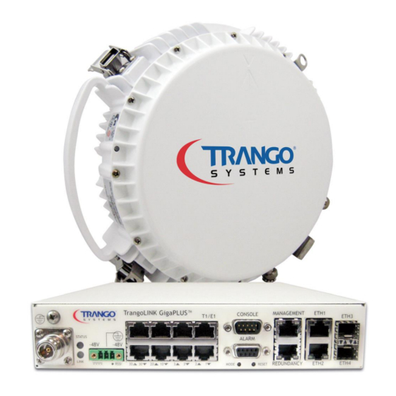
® TrangoLINK GigaPlus 6-40 GHz Split Architecture High Capacity Point-to-Point Microwave Backhaul System User Manual Revision 3.1... -
Page 2: Information To User
, TrangoLINK , and TrangoLINK Giga are registered trademarks of Trango Systems, Inc. Other names mentioned in this publication are owned by their respective holders. Statement of Conditions The information contained in this document is subject to change without notice. Trango Systems, Inc. -
Page 3: Table Of Contents
Link Protection through 1+1 Hot Standby ................31 Wireless Operation Detail ............32 Channel Bandwidth ........................32 Modulation ............................32 Mean Squared Error (MSE) ...................... 32 Adaptive Coding and Modulation (ACM)................34 Trango Systems, Inc. GigaPlus User Manual Rev 3.1... - Page 4 Firmware Upgrade ........................59 Upgrade Procedure -TFTP ....................60 Upgrade Procedure -FTP ....................62 Capacity Upgrades ........................64 Link Planning ................65 Frequency/Path Planning ......................65 Site Selection ..........................65 Licensing ............................65 Trango Systems, Inc. GigaPlus User Manual Rev 3.1...
- Page 5 System Log ..........................111 Config View..........................112 Password Settings .......................114 Other Settings ........................114 Command Line Interface (CLI) Based Configuration ............116 CLI Based 1+0 Configuration ..................116 CLI Based 1+1 Hot Standby Configuration ..............122 Antenna Alignment ........................123 Trango Systems, Inc. GigaPlus User Manual Rev 3.1...
- Page 6 ............................147 atpc ............................148 ber ..............................149 bootimage ..........................149 cableloss ..........................150 config ............................151 custom_profile ........................153 datapath ...........................153 datapattern ..........................154 date ............................155 debug ............................155 default_opmode ........................156 diagnostics ..........................157 egress_margin ........................157 eth_info .............................158 failover ............................159 Trango Systems, Inc. GigaPlus User Manual Rev 3.1...
- Page 7 .............................178 reboot ............................180 reload ............................181 remark ............................181 reset ............................182 rps ..............................183 rssi ..............................184 siglevel ............................184 snmpd ............................186 speed ............................187 status ............................191 sync ............................192 sync_state ..........................192 sysinfo ............................193 syslog ............................194 targetrssi ..........................195 Trango Systems, Inc. GigaPlus User Manual Rev 3.1...
- Page 8 DB9 Console cable Pin-outs ....................213 DB9 Alarm Port Pin-outs ......................214 Appendix D – MIB OID Listing ............215 Appendix E – Part Numbers .............. 229 GigaPlus HP ODU Sub-bands/Tuning Ranges ...............229 Accessories ...........................241 Trango Systems, Inc. GigaPlus User Manual Rev 3.1...
- Page 9 Appendix F – Link Install and Commissioning Logs ...... 242 Appendix G – Declaration of Conformity ......... 253 Glossary ....................254 Trango Systems, Inc. GigaPlus User Manual Rev 3.1...
-
Page 10: Tables
Table 12 Recommended Torque ....................72 Table 13 RSSI to Voltage Conversion ..................124 Table 14 T1/E1 Cable Wiring ......................212 Table 15 Console Cable Pin-outs ....................213 Table 16 Alarm Port Pin Functions .....................214 Trango Systems, Inc. GigaPlus User Manual Rev 3.1... -
Page 11: Figures
Figure 19 Power Connection on Front Panel ................73 Figure 20 -48 VDC Power Connector Wiring ................73 Figure 21 Ferrite ........................... 74 Figure 22 Ferrite Installed ......................... 74 Figure 23 1+1 Hot Standby (IDUs) with CBLDAT-RIU3 ............75 Trango Systems, Inc. GigaPlus User Manual Rev 3.1... - Page 12 Figure 44 SNMP Setup Page ......................99 Figure 45 Link Status Page ......................101 Figure 46 Link Test Page ........................102 Figure 47 Ethernet Statistics Page .....................103 Figure 48 TDM (T1/E1) Statistics Page ..................104 Trango Systems, Inc. GigaPlus User Manual Rev 3.1...
- Page 13 Figure 58 BNC Connector for RSSI Voltage ................123 Figure 59 EIA/TIA 568A Straight through .................211 Figure 60 EIA/TIA 568B Cross-Over ..................211 Figure 61 Console Cable Connector ..................213 Figure 62 Alarm Port Pin Identification ..................214 Trango Systems, Inc. GigaPlus User Manual Rev 3.1...
-
Page 14: Revision History
Add detail on 1+1 configuration (LEDs on GE2) Update Table 3 to add new 7 and 13 GHz TR s PENDING Updated/Improved Sections IBM Tagging 1+1 Failover setup 2 Feb 2017 Minor update to policy Trango Systems, Inc. GigaPlus User Manual Rev 3.1... -
Page 15: Preface
It is recommended that all personnel engaged in such activities be properly trained. Trango Systems disclaims all liability whatsoever, implied or express, for any risk of damage, loss or reduction in system performance arising directly or indirectly out of the failure of the customer, or anyone acting on the customer's behalf, to abide by the instructions, system parameters, or recommendations made in this document. -
Page 16: Reference Conventions
All references to external publications are shown in bold. Warranty Information ® TrangoLINK GigaPlus units purchased from Trango Systems, Inc. are warranted for one year from date of purchase. Please see www.trangosys.com for a complete description of warranty coverage and limitations. -
Page 17: Standards Compliance
RoHS Compliance ® The TrangoLINK GigaPlus product line complies with the European Union (EU) Directive 2002/95/EC on the Restriction of Hazardous Substances (RoHS). Trango Systems, Inc. GigaPlus User Manual Rev 3.1... -
Page 18: 1.0 Product Description
1000 feet long. Figures 1 and 2 show the functional block diagram of the system as they are divided between the IDU and ODU. Figure 1 IDU Functional Block Diagram Trango Systems, Inc. GigaPlus User Manual Rev 3.1... -
Page 19: Figure 2 Odu Functional Block Diagram
GigaPlus supports direct -48 Volt DC dual power to allow for redundant power supplies. The IDU power input has reverse voltage protection to prevent damage and surge suppression circuitry to reduce susceptibility to noise. Trango Systems, Inc. GigaPlus User Manual Rev 3.1... -
Page 20: Ports And Indicators - Indoor Unit
Dual Power Connector: This is a three pin pluggable terminal block. The IDU is powered by a -48V power supply (not included). The GigaPlus IDU does support the use of two power supplies for power redundancy. Trango Systems, Inc. GigaPlus User Manual Rev 3.1... - Page 21 Serial Console Port (DB9 male): 1 serial RS-232 port used to manage unit. Alarms (DB9 female): There are 2 alarm inputs which are CMOS level and are user configurable. There are 2 outputs which are dry contact rated for 50 Volt 1 Amps each. Trango Systems, Inc. GigaPlus User Manual Rev 3.1...
- Page 22 Ethernet connection for traffic and IBM. SFP modules are available to support each as follows: a. SFP-GigE-C – Copper RJ45 module to support 1000BaseT b. SFP-GigE-S – Single Mode Fiber for long haul c. SFP-GigE-M– Multimode Fiber for short haul Trango Systems, Inc. GigaPlus User Manual Rev 3.1...
-
Page 23: Location Of Serial No. And Out Of Band Mac Address
The Figure below shows the various ports on the GigaPlus HP ODU. The HP1 and HP2 ODUs have the same ports but slightly different appearance. N-Female IF RSSI Voltage Connector BNC -F Air Pressure Vent Ground Lug Figure 5 Outdoor Unit Connectors/Indicators (HP Model) Trango Systems, Inc. GigaPlus User Manual Rev 3.1... -
Page 24: Figure 6 Polarization Indicator
If the arrow is pointed left or right then horizontal polarization is being used. Polarization indicator Figure 6 Polarization Indicator Grounding Lug – ODU - The ground lug provided on the ODU should be connected to the tower/structure leg per the grounding section recommendations. Trango Systems, Inc. GigaPlus User Manual Rev 3.1... -
Page 25: Antenna Connection
1+1 hot standby application or to aggregate two channels together for more capacity. Trango can provide multiple combiner options based on the customer applications as the table shows below: Trango Systems, Inc. GigaPlus User Manual Rev 3.1... -
Page 26: Power Supply
6.5 Ampere capacity that can support multiple co-located GigaPlus units. The power supply must be kept in a temperature controlled environment within the operating temp of 0 to 40 deg C. Trango Systems, Inc. GigaPlus User Manual Rev 3.1... -
Page 27: Key Features
Description: Unlocks the 8 T1/E1 circuits on the front panel. Ethernet capacity will be reduced by the bandwidth required for the T1 and E1 tributaries. – Covers one link – (2 license keys provided) Trango Systems, Inc. GigaPlus User Manual Rev 3.1... -
Page 28: Industry Leading System Gain
System gain is one of the most important metrics for a microwave system because it has a direct relationship to the link reliability, antenna size, and transmission distance as shown in the figure below. Trango Systems, Inc. GigaPlus User Manual Rev 3.1... -
Page 29: Full Licensed Band Frequency And T/R Spacing Support
HP and HP2 ODUs which are used with the GigaPlus. The numbers represent the number of sub-bands for each frequency band. Table 3 GigaPlus Band and T/R Spacing Options Specific information on the sub-bands is shown in Appendix E. Trango Systems, Inc. GigaPlus User Manual Rev 3.1... -
Page 30: Channel Sizes From 3.5 Mhz To 80 Mhz
The Figure below shows the Adaptive Coding and modulation in action. Figure 9 Adaptive Coding and Modulation (ACM) Trango Systems, Inc. GigaPlus User Manual Rev 3.1... -
Page 31: Link Protection Through 1+1 Hot Standby
3 routed networks to allow immediate routing of the signal to the standby link. The failover time is typically less than 200 milliseconds. 1+1 is available using equal and unequal power division combiners with the same polarization for both ODUs. Trango Systems, Inc. GigaPlus User Manual Rev 3.1... -
Page 32: 2.0 Wireless Operation Detail
Distortion may come from several sources such as bad Ethernet cables (poor shield, damaged, or low quality), path degradations such as multipath, or Fresnel zone encroachment. Trango Systems, Inc. GigaPlus User Manual Rev 3.1... -
Page 33: Table 4 Mse Expected And Maximum Values
QAM64 QAM32 QAM16 QPSK Maximum Expected value IF loopback Maximum Expected value Normal operation at max power Absolute Maximum for 1E- 6 BER Sensitivity Threshold Table 4 MSE Expected and Maximum Values Trango Systems, Inc. GigaPlus User Manual Rev 3.1... -
Page 34: Adaptive Coding And Modulation (Acm)
The threshold values can be changed by the operator if desired, however the default values shown are the recommended settings. Trango Systems, Inc. GigaPlus User Manual Rev 3.1... -
Page 35: Table 5 Acm Threshold Table
The ACM feature will automatically shift the modulation level up or down based on the MSE value and the above specified thresholds. If you do not want the radio to automatically change speed settings then disable ACM. Trango Systems, Inc. GigaPlus User Manual Rev 3.1... - Page 36 The acm command provides configuration of the ACM and must be done on both sides of the link. The linktest command from the CLI can be used to view the current TX and RX modulation levels. Trango Systems, Inc. GigaPlus User Manual Rev 3.1...
-
Page 37: Wireless Link Capacity
10.8 12.2 17.42 21.8 28/30 34.82 55/56/80 49.5 365* *375 Mbps when set to speed 80 qam256, with symbol rate 49.9 Msym/sec Table 6 Max Link Capacity (Mbps) for non-ACM Speed Settings Trango Systems, Inc. GigaPlus User Manual Rev 3.1... -
Page 38: Automatic Transmit Power Control (Atpc)
QAM256 within the 6 GHz band is the same for 3.5 MHz channels as it is for 56 MHz channels. The table illustrates this and shows the maximum set power levels for each model family, band, and modulation level. Trango Systems, Inc. GigaPlus User Manual Rev 3.1... -
Page 39: Transmitter Minimum Power Output
The levels are also the minimum levels that ATPC can set the output to when enabled. Transmitter Minimum Power Output Level (dBm) HP ODU Model HP1-XX-YYYY-ZZ HP2-XX-YYYY-ZZ Table 8 Minimum TX set power by band Trango Systems, Inc. GigaPlus User Manual Rev 3.1... -
Page 40: Receiver Maximum Input
Modulation Level Max RSSI 256 QAM -24 dBm 128 QAM -22 dBm 64QAM -20 dBm 32QAM -18 dBm 16QAM -16 dBm QPSK -14 dBm Table 9 Max Receive Level Input Trango Systems, Inc. GigaPlus User Manual Rev 3.1... -
Page 41: 3.0 Network Operation Detail
2 or 3 routing to reroute the traffic the other direction if the link fails. The Figure below shows the non-protected 1+0 link setup with switches or routers. Figure 10 1+0 Setup Trango Systems, Inc. GigaPlus User Manual Rev 3.1... -
Page 42: 1+1 Hot Standby Protected Link Configuration
To assist in this process, Rapid Port Shutdown (RPS) can be enabled on the failed unit as an action after a failover occurs. Figure 11 1+1 Setup Trango Systems, Inc. GigaPlus User Manual Rev 3.1... -
Page 43: Hardware Triggered Failover
2) The standby GigaPlus utype will change from standby to active and the previously active unit utype will change to standby. 3) The Ethernet port will be shut down on the new standby unit if RPS was enabled. Trango Systems, Inc. GigaPlus User Manual Rev 3.1... -
Page 44: Software Triggered Failover
1. Using the utype_switch command to restore the active after a failover a. This command can only be initiated on the Active unit. b. A low level command is sent from Active to Standby unit to turn on transmitter. Trango Systems, Inc. GigaPlus User Manual Rev 3.1... -
Page 45: Rapid Port Shutdown (Rps)
(See Quality of Service Section). Untagged IBM is also supported in Firmware release 3.0 and Trango Systems, Inc. GigaPlus User Manual Rev 3.1... -
Page 46: Port Mapping (802.1Q)
In Band Management (IBM) with VLAN tagging will not operate with the smart mode turned off. Out of band management and IBM with VLAN tagging off (SW V3.0) will still be available as when Smart Mode is off. Trango Systems, Inc. GigaPlus User Manual Rev 3.1... -
Page 47: Quality Of Service (Qos) (802.1P And Diffserv)
These default mappings can be changed with the qos command, allowing the packets to be mapped into any one of the 8 queues based on the COS bit in the VLAN tag. Different priority tags may be mapped into the same queue if desired. Trango Systems, Inc. GigaPlus User Manual Rev 3.1... -
Page 48: Port Priority
Traffic coming into the Ethernet ports is bursty by nature and may exceed the radio link capacity if the radio speed is less than the Ethernet line speed (10/100/1000 Mbps). To Trango Systems, Inc. GigaPlus User Manual Rev 3.1... - Page 49 Also, the Egress margin may need to be further reduced for strict QoS modes when datapath is set to Eth+t1 or Eth+E1 since the actual channel capacity for Ethernet is reduced by roughly 12 or 16 Mbps , respectively. Trango Systems, Inc. GigaPlus User Manual Rev 3.1...
-
Page 50: 4.0 Link Management
The factory configuration for IP address is 192.168.100.100 for all units, and the IBM default address is 172.16.1.1 for the ”A” side unit and 172.16.1.2 for the ”B” side unit. Default Passwords The default passwords are shown in the table below: Trango Systems, Inc. GigaPlus User Manual Rev 3.1... -
Page 51: Graphical User Interface (Web Browser)
10). Enter the default or modified user name and password then press OK. Either HTTP or HTTPS may be used. Figure 12 Web Browser Login The first page to display will be the System Info Page as shown in the Image below: Trango Systems, Inc. GigaPlus User Manual Rev 3.1... -
Page 52: Figure 13 System Status Version Page
Radio Setting: The essential Radio Link setup parameters, TX/RX frequency, transmitter power, ATPC, speed and modulation, as well as the capacity license are found here. Settings for 1+1 failover are found here as well. Trango Systems, Inc. GigaPlus User Manual Rev 3.1... - Page 53 User Setting: User can change the web view and config passwords, change the system remark field and change the web refresh rate. Trango Systems, Inc. GigaPlus User Manual Rev 3.1...
-
Page 54: Command Line Interface (Cli) Using Ssh, Telnet Or Console
CLI login: admin Password: ( No characters will be display during input Trango System: TrangoLINK GigaPlus Command Line Interface v1.0.0 (CLI-view)# If the incorrect password is entered during login, the system will allow two more tries before terminating a telnet session. A new session will need to be open to try again. - Page 55 SAVE ALL CONFIGURATION CHANGES The operator can go back to the “view” node by using the exit command from the config node. Example: CLI login: admin Password: Trango System: TrangoLINK GigaPLUS Command Line Interface v1.3.0 (CLI-view)# config Password: (CLI-config)# (CLI-config)#exit SUCCESS (CLI-view)# Trango Systems, Inc.
-
Page 56: Changing Password
CLI-config prompt. If the password is lost and the unit is locked, the pushbutton on the access panel can be used to reset the password and default IP back to the factory settings Trango Systems, Inc. GigaPlus User Manual Rev 3.1... -
Page 57: Console Port
These capabilities allow the network operator to provide superior services through higher network accessibility and integrated accounting system. Use of SNMP requires the customer to have already implemented a NMS or SNMP software package. Trango Systems, Inc. GigaPlus User Manual Rev 3.1... -
Page 58: Common Objects For Monitoring And Control
rfRSSI: The Receive Signal Strength Indication in dBm the unit receives from the ODU . Commonly referred to as Receive Signal Level (RSL) Link Status Traps Various traps are defined as follows: Trango Systems, Inc. GigaPlus User Manual Rev 3.1... -
Page 59: Firmware Upgrade
Add a “ .0 “ at the end of the OID string Firmware Upgrade The firmware on the TrangoLINK GigaPlus can be updated to a newer version through IBM or OBM Ethernet Ports. A firmware release consists of up to two files which... -
Page 60: Upgrade Procedure -Tftp
The default config node password is “trango” 5) Enable the tftp daemon using the tftpd command as shown below. Login as: admin Password: Trango System: TrangoLink GigaPLUS Command Line Interface v1.3 (CLI-view)# config Password: Trango Systems, Inc. GigaPlus User Manual Rev 3.1... - Page 61 If the ODU firmware was also being upgraded, the ODU file would be transferred to the GigaPlus ODU using the same method as the IDU file. After loading the file, the bootimage upgrade odu command would be used to write it to FLASH. Trango Systems, Inc. GigaPlus User Manual Rev 3.1...
-
Page 62: Upgrade Procedure -Ftp
FTP server IP address from the debug prompt. 3) Next , get the file from the FTP server by typing the get command from the ftp prompt. ftp> get <file_name> Trango Systems, Inc. GigaPlus User Manual Rev 3.1... - Page 63 4) Logout of the ftp session ftp> logout: logout of ftp session. 5) Run the bootimage omu and/or bootimage odu command as required. Trango Systems, Inc. GigaPlus User Manual Rev 3.1...
-
Page 64: Capacity Upgrades
“Enable” will be displayed as shown below and replace the blank field. Figure 16 Capacity Upgrade in Link Setup Page The capacity key can also be entered using the license command from the command line interface. Trango Systems, Inc. GigaPlus User Manual Rev 3.1... -
Page 65: 5.0 Link Planning
Licensing of spectrum is typically done on an individual path basis. In the US, the FCC will grant licenses for 11 years for paths that do not interfere with other users after the coordination and fees have been paid. Contact Trango for more information on the above topics. Trango Systems, Inc. GigaPlus User Manual Rev 3.1... -
Page 66: 6.0 Installation
1) Determining the RF exposure risk. If necessary ask the structure/tower owner or operator. When necessary, wear a protective suit or have the transmitter(s) switched off for the duration of the installation. Trango Systems, Inc. GigaPlus User Manual Rev 3.1... - Page 67 Ambient Temperature: The ambient temperature range for the GigaPlus ODU is -40° to +65° Celsius, and -5° to +55° Celsius for the IDU. To ensure operation and to maximize Trango Systems, Inc. GigaPlus User Manual Rev 3.1...
- Page 68 Access to the tower and ODU/antenna location must be restricted. Note: For USA: In restricted access areas install the GigaPlus system in accordance with articles 110-26 and 110-27 of the 2002 National Electrical Code ANSI/NFPA 70. Trango Systems, Inc. GigaPlus User Manual Rev 3.1...
-
Page 69: Installation Process
Stranded 18 AWG wire for power connection Stranded 12 AWG wire for ODU and IDU ground connections Wire Insulation strippers for ground and power wire Terminal crimpers for ground and power wire Trango Systems, Inc. GigaPlus User Manual Rev 3.1... -
Page 70: Grounding Overview
A Ground wire of AWG 12 or larger should be used and grounded to an Earth grounded tower leg or Bus Bar before entry into the shelter. Figure 16 shows the overall ground design. Figure 17 Site Based Grounding Diagram Trango Systems, Inc. GigaPlus User Manual Rev 3.1... -
Page 71: Power Supply Installation
NOTE: Ensure that only a -48 Volt Supply is used and that the wiring is correct. If a +48 VDC supply is used and the Earth ground is wired to the negative terminal shown in the figure, permanent damage to the unit may occur. Trango Systems, Inc. GigaPlus User Manual Rev 3.1... -
Page 72: Antenna Installation
A single IDU with the Rack Ears installed is shown in the Figure below. It is recommended to always install the IDU on the left side to reduce the length of the grounding wire to the rack. Figure 18 IDU with Rack Ears installed Trango Systems, Inc. GigaPlus User Manual Rev 3.1... -
Page 73: Connecting Power
Tighten the two #2 screws to the chassis after installation of the connector to prevent it from pulling out. -48V (2 positions) Ground (+) Figure 20 -48 VDC Power Connector Wiring Trango Systems, Inc. GigaPlus User Manual Rev 3.1... -
Page 74: Ferrite Installation
Be sure to install the ferrite as close as possible to the IDU power plug as shown in Figure 22 to improve the noise rejection. Figure 21 Ferrite Figure 22 Ferrite Installed Trango Systems, Inc. GigaPlus User Manual Rev 3.1... -
Page 75: 1+1 Hot Standby Idu Installation
The dummy panel is removed in this case. CBLDAT-RIU3 Figure 23 1+1 Hot Standby (IDUs) with CBLDAT-RIU3 Trango Systems, Inc. GigaPlus User Manual Rev 3.1... -
Page 76: Hp Odu Installation On Antenna
“V” should be at the side of the unit. The IF connector should be positioned towards the lower right for vertical and lower left for horizontal polarization. Trango Systems, Inc. GigaPlus User Manual Rev 3.1... -
Page 77: Figure 25 Polarization Indication
Secure the latches that have eyelets with locks if desired. Latch with Eyelet Figure 26 Latch Trango Systems, Inc. GigaPlus User Manual Rev 3.1... -
Page 78: If Cable Installation
Cable Connectivity – The IF Cable can be connected to the ODU and IDU with right angle N adapters (female towards the cable and male to the IDU/ODU) which prevent the bend radius (minimum 1 inch) from obstructing cabinet doors. Trango Systems, Inc. GigaPlus User Manual Rev 3.1... -
Page 79: Figure 27 Right Angle N-Connector Mount
Cable Type -Trango strongly recommends the use of quality LMR-400 cable and top of the line connectors complimented by well-trained installation personnel following manufacturer’s instructions. Other types of cable may not have adequate shielding and may cause or receive outside interference. Trango Systems, Inc. GigaPlus User Manual Rev 3.1... -
Page 80: Weather Proofing Cabling
Weather Proofing Cabling It is important to properly seal each antenna connection to protect against moisture and corrosion. Trango Systems recommends using Coax-Seal which should be applied over the ODU N-Type connector. Coax-Seal is a gum-like tape which is applied by wrapping around the connector and then compressed/molded to form a single cohesive protective covering over the connector. -
Page 81: 1+1 Hot Standby Odu Installation
The ODUs must be mounted using the same polarization for 1+1 hot standby operation. For more detail see the manual for the SMC-XX-XX combiner family. Figure 30 ODUs on SMC combiner (1+1) Trango Systems, Inc. GigaPlus User Manual Rev 3.1... -
Page 82: 7.0 Link Configuration
Only the IP addresses need to be changed and the Opmode needs to be enabled at both ends. It is still recommended to set the date and run the status save command to record the known good state of the link after installation, alignment and link testing Trango Systems, Inc. GigaPlus User Manual Rev 3.1... -
Page 83: Web Based Configuration
A login window will pop up, requiring the user to enter username and password (See Figure 33). Enter the default user name and password (user: admin, password: trango) and click OK. Figure 32 Web Login with Password Trango Systems, Inc. GigaPlus User Manual Rev 3.1... -
Page 84: Figure 33 System Information Page (View Mode)
To login, enter user: config, password: trango. This display format will change to that shown below. Trango Systems, Inc. GigaPlus User Manual Rev 3.1... -
Page 85: Figure 34 System Information Page (Config Mode)
Subnet, and Gateway to the address that is desired for the Out- of-band Management Port. Click Submit. At this point the Web session will terminate and the operator must login again using the new IP address. Trango Systems, Inc. GigaPlus User Manual Rev 3.1... -
Page 86: Figure 35 Ip Configuration Page
All the parameters should match those submitted and approved by the licensing agency. c. Set the Odupower to “On” if it is not already on. d. Turn the Opmode to “Off” if it is not already off. Trango Systems, Inc. GigaPlus User Manual Rev 3.1... -
Page 87: Figure 36 Link Setup Page
The link should now be established between the two sides. The Active Link indicators will turn green and the RSSI and MSE levels will change according to the link distance or attenuation used (bench) Trango Systems, Inc. GigaPlus User Manual Rev 3.1... -
Page 88: Web Based 1+1 Setup
7) Set the same failover mode on the spare radios to become standby units. They will detect the Active units and the Active will sync the config to the standby Trango Systems, Inc. GigaPlus User Manual Rev 3.1... - Page 89 10) Click the Config Save button at the lower left of any webpage – This must be done on both sides of the link. Trango Systems, Inc. GigaPlus User Manual Rev 3.1...
-
Page 90: Adaptive Coding And Modulation (Acm) (Optional)
Select the “On” button and then click on the submit button to make the change if ACM is desired. Figure 38 ACM Setup Trango Systems, Inc. GigaPlus User Manual Rev 3.1... -
Page 91: Automatic Transmit Power Control (Atpc) (Optional)
The Rapid Port Shutdown can be enabled or disabled here as well to allow for routing protocols to reroute traffic if the link should go down. Trango Systems, Inc. GigaPlus User Manual Rev 3.1... -
Page 92: Figure 39 Atpc Setup/ Rps /Telnetd/ Tftpd/Alarms
Figure 39 ATPC Setup/ RPS /Telnetd/ tftpd/alarms Trango Systems, Inc. GigaPlus User Manual Rev 3.1... -
Page 93: Figure 40 Threshold Setup Page
Figure 40 Threshold Setup Page Trango Systems, Inc. GigaPlus User Manual Rev 3.1... -
Page 94: Ethernet Configuration
The SFP ports, GE3 and GE4 are fixed at 1000Base T but can accommodate single and multimode fiber modules as well as copper. Trango Systems, Inc. GigaPlus User Manual Rev 3.1... -
Page 95: Figure 41 Ethernet Setup Page
The incoming priority levels can be mapped to the queues in the Ethernet QoS Settings box. For WRR Mode, the Diffserv tag in the incoming IP packets can be used to map the packet to a priority, and then to a queue . Trango Systems, Inc. GigaPlus User Manual Rev 3.1... -
Page 96: Figure 42 Qos Setup Page For Strict Mode
This is done for each Ethernet port individually by selecting the ETH1 to ETH4 tab in the box. For convenience, common class identifiers are shown along with the corresponding DSCP value below: Trango Systems, Inc. GigaPlus User Manual Rev 3.1... - Page 97 CS7(precedence 7) maps to dscp 56 (111000) EF maps to dscp 46 (101110) Default settings for priority of DSCP are all 0, so the user must change the priority for each Code Point according to the desired Priority. Trango Systems, Inc. GigaPlus User Manual Rev 3.1...
-
Page 98: Figure 43 Qos Setup Page For Wrr Mode
Figure 43 Qos Setup Page for WRR Mode Trango Systems, Inc. GigaPlus User Manual Rev 3.1... -
Page 99: Status Monitoring Overview
The Web interface provides many ways to look at the status of the traffic flowing across the link and the health of the link. The following Figures show the various counters that can be monitored. Trango Systems, Inc. GigaPlus User Manual Rev 3.1... -
Page 100: Link Status
All the link status indicators should be green when working properly. Red usually indicates that an ODU is off or not connected. A grey status indicator represents an indicator that does not apply for the model of ODU being used. Trango Systems, Inc. GigaPlus User Manual Rev 3.1... -
Page 101: Figure 45 Link Status Page
Figure 45 Link Status Page Trango Systems, Inc. GigaPlus User Manual Rev 3.1... -
Page 102: Figure 46 Link Test Page
Figure 46 Link Test Page Trango Systems, Inc. GigaPlus User Manual Rev 3.1... -
Page 103: Ethernet Statistics
IN: Means traffic been received from the device (Switch / Router) attached to the particular GigE port. OUT: Means traffic sent from the IDU to the device attached to the particular GigE port Figure 47 Ethernet Statistics Page Trango Systems, Inc. GigaPlus User Manual Rev 3.1... -
Page 104: T1/E1 Statistics
Contains industry standard statistical information on each T1/E1 interface, updated every 20 seconds. The information on this page only applies when the datapath is set to Eth+T1 or Eth +E1. Figure 48 TDM (T1/E1) Statistics Page Trango Systems, Inc. GigaPlus User Manual Rev 3.1... -
Page 105: Rf Statistics
The Port rate is updated every 20 seconds. The Port Util is a percentage of the total available radio capacity being used and is also updated at 20 second intervals. Figure 49 RF Statistics Page Trango Systems, Inc. GigaPlus User Manual Rev 3.1... - Page 106 Trango Systems, Inc. GigaPlus User Manual Rev 3.1...
-
Page 107: Diagnostic Options
Config Import command. Config Import allows the previously exported config file to be saved into the IDU non volatile memory. The file must first be uploaded to the IDU. Reboot is required. Trango Systems, Inc. GigaPlus User Manual Rev 3.1... -
Page 108: Figure 50 Diagnostic Options
The Link will be broken during the test so ensure that a maintenance window is planned. For a single iteration the link will be down for up to 10 seconds. Trango Systems, Inc. GigaPlus User Manual Rev 3.1... -
Page 109: Figure 51 Loopback Auto Page
Siglevel – This command will display details about the actual TX and RX signal levels, signal quality, and ODU communication stats. Trango Systems, Inc. GigaPlus User Manual Rev 3.1... -
Page 110: Figure 52 Status Display Page
Figure 52 Status Display Page Trango Systems, Inc. GigaPlus User Manual Rev 3.1... -
Page 111: System Log
The system log records events, errors, and statistics with time stamps attached. The Syslog Export process is similar to the Diagnostic Export process (See Diagnostic Export above). The name of the file to download is syslog.txt Trango Systems, Inc. GigaPlus User Manual Rev 3.1... -
Page 112: Config View
Config View allows complete display of the current system configuration. By selecting the “config View” option from the pull down menu, then “submit, the display will be shown. The window is scrollable and expandable on most browsers. Trango Systems, Inc. GigaPlus User Manual Rev 3.1... -
Page 113: Figure 55 Config View
Figure 55 Config View Trango Systems, Inc. GigaPlus User Manual Rev 3.1... -
Page 114: Password Settings
Setting the web refresh rate to 0 will stop the automatic web refreshing, and the reload button on the browser must be used to update the fields o nthe web page. Trango Systems, Inc. GigaPlus User Manual Rev 3.1... -
Page 115: Figure 57 Other Settings
Figure 57 Other Settings Trango Systems, Inc. GigaPlus User Manual Rev 3.1... -
Page 116: Command Line Interface (Cli) Based Configuration
IP address of 192.168.100.100. Use the windows telnet program or any other telnet client program. When prompted for the Login enter admin and for password, enter trango. The Trango Systems command line interface application should respond as follows: Microsoft Windows XP [Version 5.1.2600]... - Page 117 Netmask: 255.255.254.0 SUCCESS After re-connecting, change the gateway address as necessary. (CLI-config)# ipconfig gateway 10.14.0.1 Gateway IP: 10.14.0.1 SUCCESS Confirm that the changes are made: (CLI-config)# ip (CLI-config)# ipconfig IP Address: 10.14.1.41 Trango Systems, Inc. GigaPlus User Manual Rev 3.1...
- Page 118 Enter the transmit frequency in MHz (the resolution of the frequency is .250 MHz). The receive frequency will automatically be programmed as follows: For A models, RX Freq = TX freq + Freq Duplex. For B models, RX Freq= TX Freq – Freq Duplex. Trango Systems, Inc. GigaPlus User Manual Rev 3.1...
- Page 119 If ACM is desired, the acm enable command should be used on both ends of the link. IMPORTANT: After the ACM is enabled after initial link establishment, the speed command must be reissued. (CLI-config)# acm enable on ACM enable: SUCCESS Trango Systems, Inc. GigaPlus User Manual Rev 3.1...
- Page 120 64QAM, 32QAM, etc. for Tx or Rx. The RSSI will also likely change for rain fading, but may remain unchanged if the link degradation is due to multipath. The modulation/RSSI will automatically return to the set value once the fading condition has passed. (CLI-config)# linktest Trango Systems, Inc. GigaPlus User Manual Rev 3.1...
- Page 121 FLASH memory. If a power interruptions should occur, the link will re-establish itself after the interruption is over . (assumes default_opmode on was enabled and the configuration saved prior to the power interruption). Trango Systems, Inc. GigaPlus User Manual Rev 3.1...
-
Page 122: Cli Based 1+1 Hot Standby Configuration
7) Use config save on all units to ensure the sync’d configuration is saved. 8) If desired, test a hardware switchover with utype_switch. Trango Systems, Inc. GigaPlus User Manual Rev 3.1... -
Page 123: Antenna Alignment
(a higher negative number) while adjusting. When the lock status changes to 1, you may fine tune the alignment with the LED display Antenna Alignment Procedure Ensure that both sides of the link are configured correctly. Connect to the management port of the GigaPlus. Trango Systems, Inc. GigaPlus User Manual Rev 3.1... -
Page 124: Table 13 Rssi To Voltage Conversion
Table 13 RSSI to Voltage Conversion 5. Once satisfied with the RSSI reading, tighten down the antenna in the optimum position. 6. Replace the sealing cap on the BNC connector and tighten until it clicks into place. Trango Systems, Inc. GigaPlus User Manual Rev 3.1... -
Page 125: Cli Common Task Reference
Change the IBM IP address and subnet mask. Each end of the link should have a different IP address, and in the case of multiple daisy chained links, the IPs should all be different. (CLI-config)# ibm ip 172.16.1.2 255.255.255.0 IBM IP Address: 172.16.1.2 IBM netmask: 255.255.255.0 Trango Systems, Inc. GigaPlus User Manual Rev 3.1... - Page 126 Note: Besides ping , It should be noted that from the debug prompt a telnet session can be run to configure the far end if desired. It should be kept in mind that any Trango Systems, Inc. GigaPlus User Manual Rev 3.1...
- Page 127 Trango System: TrangoLINK GigaPlus Command Line Interface v3.0.0 Return to the config node using the config command (CLI-view)# config Password: IBM may function with VLAN tagging enabled or disabled.
-
Page 128: Capacity License Activation
+17 dBm, so the atpc max_power is set accordingly. (CLI-config)# atpc max_power 17 ATPC max power: 17.00 SUCCESS (CLI-config)# atpc ATPC Enable: ATPC Step Size: ATPC Max Power: 17.00 Trango Systems, Inc. GigaPlus User Manual Rev 3.1... -
Page 129: Check Ethernet And Rf Port Statistics
The port rate and port utilization (percent) are also useful for monitoring since they can indicate a link running at capacity. These two metrics account for the sum of all the Ethernet ports being used. Trango Systems, Inc. GigaPlus User Manual Rev 3.1... - Page 130 The status clear command will clear all port counters and the BER counters. (CLI-config)# status clear Run the syslog clear command Trango Systems, Inc. GigaPlus User Manual Rev 3.1...
-
Page 131: Enable Traps (Optional)
If thresholds have been set and SNMP Trap assigned as an action, the crossing of the threshold will generate a trap. The current trap information using the trap command. The current trap manager IP addresses are shown along with their individual status: (CLI-config)# trap Trango Systems, Inc. GigaPlus User Manual Rev 3.1... - Page 132 Enable the trap number 1 using the trap enable 1 on on command – The trap will be enabled and the status shown: CLI-config)# trap enable 1 on Enable Trap 1: 10.14.1.5 Trango Systems, Inc. GigaPlus User Manual Rev 3.1...
-
Page 133: 8.0 Troubleshooting
6) IF ACM is being used, ACM may not be enabled on both ends of the link. Enable the ACM and reset the speed on each end. The speed must be set the same on both ends. MSE is too high and/or bit errors are showing when running linktest Trango Systems, Inc. GigaPlus User Manual Rev 3.1... -
Page 134: Receive Signal Level Is Too Low
ATPC is enabled . 2) Reported RSSI more than 3 dB off the expected RSSI: There may be an alignment problem with one or both antennas, especially if both sides of the link show the Trango Systems, Inc. GigaPlus User Manual Rev 3.1... -
Page 135: Rf Link Is Good But Packet Loss Is Occurring
If you cannot telnet into the IDU or open an HTTP browser session, 1) Check your Ethernet and power cable connections 2) Ensure proper cable is being used cross-over vs. straight-through cable. The LEDs on the Ethernet port should be illuminated. Trango Systems, Inc. GigaPlus User Manual Rev 3.1... -
Page 136: No Radio Management Connection Over The Link
If there are still problems please contact Technical Support at 858-391-0010 or Email at techsupport@trangosys.com Before calling please make sure you have the following information. Serial Number Description of the problem Steps taken so far to resolve the problem Commissioning log Trango Systems, Inc. GigaPlus User Manual Rev 3.1... -
Page 137: Appendix A - Command Line Interface Reference
Moves the cursor one character to the right. Up Arrow Recalls commands in the history buffer, beginning with the most recent command. Repeat the key sequence to recall successively older commands. Down Arrow Trango Systems, Inc. GigaPlus User Manual Rev 3.1... -
Page 138: Different Node Levels
Display failover (1+1 HSB) mode fanctrl Display Fan status freq Display Rf Tx/Rx frequency guard_time Display failover guard time help Display help command httpd Display Web server (httpd) status Display In Band Management configuration Trango Systems, Inc. GigaPlus User Manual Rev 3.1... - Page 139 Current 1+1 HSB peer sync status (Failover active) sysinfo Display MSE, FER information syslog Display system event log targetrssi Display target rssi value Display TDM configuration telnetd Display telnetd server (telnetd) status Trango Systems, Inc. GigaPlus User Manual Rev 3.1...
-
Page 140: Config Node
Users can go back to the “view” node by typing in the command exit Config Node Command List Ranges Default Value enable <on|off>, mod alarm Alarm 1 and 2 <on|off> alignment_mode <on|off> enable <on|off>, max_power, step_size atpc <1-99> seconds Trango Systems, Inc. GigaPlus User Manual Rev 3.1... - Page 141 0 (this is exception to the valid range) freq_duplex ODU dependent guard_time 10-30 seconds 15 seconds help / ? httpd <on|off> <on|off> <ip address> <Vlan> iduled <0|1> (TDM|RSSI) RSSI ipconfig <ip address><netmask><gateway> 192.168.100.100 netmask: 255.255.255.0 gateway: 192.168.100.100 Trango Systems, Inc. GigaPlus User Manual Rev 3.1...
- Page 142 COS Queue = 3 Priority 4: COS Queue = 4 Priority 5: COS Queue = 5 priority<0-7>, dscp_weight <1-15>, Priority 6: COS Queue = 6 mode<strict/WRR> Priority 7: COS Queue = 7 Trango Systems, Inc. GigaPlus User Manual Rev 3.1...
- Page 143 Port 1 DSCP mappings shown reboot TrangoLink GigaPLUS remark <string 1-100bytes> Reset will not change the remark settings reset reload in x <1-240> minutes 10 minutes <on|off> Default 1 (if duration not entered by rssi Duration <1-99> user)
- Page 144 0.0.0.0 Reset will change the prev configured trapip trap <enable, ip, cr> enable <0 – 5> <1 -5 > <A.B.C.D> uptime utype Main utype_switch version voltage web_refresh_rate <2-300 seconds> <0> to disable Trango Systems, Inc. GigaPlus User Manual Rev 3.1...
-
Page 145: Debug Node
Display the current system routing table <ip address> ssh into another host syslog print system log telnet <ip address> telnet into another host uptime Display the current uptime and system load tg_reboot Reboot radio Trango Systems, Inc. GigaPlus User Manual Rev 3.1... -
Page 146: Individual Command Details
The speed command needs to be issued after “acm enable on/off” command. ACM is not symmetric and each end (TX/RX) may have different profiles at a given time depending upon the MSE values on each end. Trango Systems, Inc. GigaPlus User Manual Rev 3.1... -
Page 147: Alarm
DESCRIPTION User may specify alarm1 or alarm2 as the action in the threshold settings. This command is used to turn off the alarm after the alarm has been Trango Systems, Inc. GigaPlus User Manual Rev 3.1... -
Page 148: Atpc
User cannot execute the power command when ATPC is turned on. The system will adjust the power automatically based on the “max_power” and “step_size”. atpc step_size: Specified the step size for each of the ATPC command for power up/down Trango Systems, Inc. GigaPlus User Manual Rev 3.1... -
Page 149: Ber
It will always be zero on live traffic (external datapattern). bootimage SYNTAX bootimage toggle bootimage upgrade <idu | odu> Default: N/A Trango Systems, Inc. GigaPlus User Manual Rev 3.1... -
Page 150: Cableloss
Configuration Storage: Yes cableloss without any parameter will display the current cableloss values for the IF cable going to the ODU Valid range of operation: loss140: range 0-15, loss315: range 0-26, loss915: range 0-50 Trango Systems, Inc. GigaPlus User Manual Rev 3.1... -
Page 151: Config
The option allows the user to execute a recently imported config file that was previously saved on a storage media outside the IDU. The file must have been imported using the config import command described below Trango Systems, Inc. GigaPlus User Manual Rev 3.1... - Page 152 Multiple changes can be saved by one save command. config view: The option displays the current system configuration in ASCII format on the console. The saved config is displayed. Trango Systems, Inc. GigaPlus User Manual Rev 3.1...
-
Page 153: Custom_Profile
DEFAULT VALUE DESCRIPTION Allow a custom speed profile to be used. The custom file must be created by Trango Systems and verified before use. Custom speed profiles allow changing various parameters such as Channel bandwidth, ACM profile, Latency, Sensitiivity, number of T1/E1 tributaries, etc. -
Page 154: Datapattern
DESCRIPTION Sets datasource for the modem. datapattern can be generated from either fpga (external) or the modem (internal), used to generate PRBS data Trango Systems, Inc. GigaPlus User Manual Rev 3.1... -
Page 155: Date
DESCRIPTION Allow the user to set and read the current time and date debug SYNTAX debug Default: N/A Configuration Storage: No Trango Systems, Inc. GigaPlus User Manual Rev 3.1... -
Page 156: Default_Opmode
Configuration Storage: Yes default_opmode without any parameter will display the default operational mode DESCRIPTION Set the default opmode to user specified input. If ON, the system to power on with ready to be operational Trango Systems, Inc. GigaPlus User Manual Rev 3.1... -
Page 157: Diagnostics
Diagnostic command is to communicate with all system devices and get a current snapshot of the system status. This is mainly used for debugging purposes. egress_margin SYNTAX egress_margin <-99 to +99> Default: 0 Configuration Storage: Yes egress_margin is a system-level command. Trango Systems, Inc. GigaPlus User Manual Rev 3.1... -
Page 158: Eth_Info
For most applications, the default setting of is sufficient. eth_info SYNTAX eth_info eth_info <1-4> <1-4> <1-4> <1-4> Default: N/A Configuration Storage: No eth_info without any parameter will display configuration for all 4 ports. eth_info is a system-level command. Trango Systems, Inc. GigaPlus User Manual Rev 3.1... -
Page 159: Failover
NOTE: This command will set the utype state to default and perform election period which will affect the radio link. Therefore, it is not recommended to be executed while the link is running with traffic. Trango Systems, Inc. GigaPlus User Manual Rev 3.1... -
Page 160: Fanctrl
Display of the status of the cooling fan in the chassis and allow it to be turned on and off. It is not recommended to turn the fan off if the ambient temperature surroundingthe IDU will exceed 10 deg C. Trango Systems, Inc. GigaPlus User Manual Rev 3.1... -
Page 161: Freq
Certain IDU/ODU PLL synthesizers are programmed for each and every individual frequency. GigaPlus supports model 6, 6E, 11, 11E, 15, 18, 18E, 23, 23E of SP ODU’s And 6-38Ghz HP ODU’s freq_duplex SYNTAX freq_duplex [duplex] Default: 0 Configuration Storage: Yes Trango Systems, Inc. GigaPlus User Manual Rev 3.1... -
Page 162: Ftp
<file_name>: Do NOT supply the path to the file that needs to be put on to the. It will be stored in the default system directory See example below. ftp> put <source file> <destination>: source will be the filename only,. Trango Systems, Inc. GigaPlus User Manual Rev 3.1... -
Page 163: Help
(CLI-eng)# ftp 10.14.0.85 trango EXAMPLE Password: ftp>get zImage ####################################################### Get operation successful with passive mode ftp>put linkloss.txt linkloss.txt ####################################################### Put operation successful with passive mode ftp>logout (CLI-config)# help / ? SYNTAX Trango Systems, Inc. GigaPlus User Manual Rev 3.1... -
Page 164: Guard_Time
DESCRIPTION Guard time is only valid with failover feature enabled. Whenever a switchover has occurred, the guard time will be started and within the Trango Systems, Inc. GigaPlus User Manual Rev 3.1... -
Page 165: Httpd
Turn on httpd server for web interface access. The web interface supports both secure (https) and normal (http) access. SYNTAX ibm enable < on | off > ibm ip <ip_addr> <netmask> ibm port <1-4: ge1-ge4> Trango Systems, Inc. GigaPlus User Manual Rev 3.1... -
Page 166: Ipconfig
OBM port on the IDU. The 2 IP addresses need to be unique. ipconfig SYNTAX ipconfig ipconfig ip [ip_addr] [netmask] ipconfig gateway [default_gateway_ip] Default: IP=192.168.100.100, NETMASK=255.255.255.0, GATEWAY=192.168.100.100 Configuration Storage: Yes ipconfig without any parameter will display the current IP configuration Trango Systems, Inc. GigaPlus User Manual Rev 3.1... -
Page 167: License
(> 100Mbps) on the radio. Speed key 1 enables speed up to 200Mbps and speed key 2 enables Max speed. Please refer to the actual speed/modulation/channel width combination for valid profiles. Trango Systems, Inc. GigaPlus User Manual Rev 3.1... -
Page 168: Link_History
Link steady: current status of link steady flag. Defined to be approximately 40 seconds after the link has been established. linktest SYNTAX linktest <iterations> Iteration range from 1-99 seconds Default: default iteration = 1 second Trango Systems, Inc. GigaPlus User Manual Rev 3.1... -
Page 169: Loglevel
RSSI: The current RSSI value MSE: The current MSE value BER : The instantaneous BER value (1sec interval) loglevel SYNTAX loglevel [0-2] <0: Setting, 1: Event, 2: Status>Default: 2 Configuration Storage: Yes Trango Systems, Inc. GigaPlus User Manual Rev 3.1... -
Page 170: Loopback
This command will automaticall turn the Ethernet ports off as well and prevent a loop from occurring on the network. Trango Systems, Inc. GigaPlus User Manual Rev 3.1... -
Page 171: Model
Display current ODU/IDU model and serial ID. The following information are been displayed: ODU model, IDU model, ODU Serial ID, IF Rev, IF Serial, IDU Model, IDU Serial ID for each radio SYNTAX Trango Systems, Inc. GigaPlus User Manual Rev 3.1... -
Page 172: Oduled
Default: ON Configuration Storage: YES oduled without any parameter will display the current status of ODU LED display DESCRIPTION Turn ON/OFF ODU led for display RSSI value. Applies only to SP ODUs odupower Trango Systems, Inc. GigaPlus User Manual Rev 3.1... -
Page 173: Odurxagc
IDU from the ODU and keeps the received level within a predefined range. This helps to improve MSE and maintain better system performance in fading conditions. Trango Systems, Inc. GigaPlus User Manual Rev 3.1... -
Page 174: Opmode
ODU Rx AGC: off RELATED targetrssi, cableloss opmode SYNTAX opmode opmode < on| off > Default: OFF Configuration Storage: NO opmode without any parameter will display the current status of ODU operation mode Trango Systems, Inc. GigaPlus User Manual Rev 3.1... -
Page 175: Passwd
DESCRIPTION Update the current password for entering “config-node”. The new pasword takes effect only after a reboot command or re-enter the “view- node” from debug prompt with cli command. port Trango Systems, Inc. GigaPlus User Manual Rev 3.1... - Page 176 COS field in the tagged traffic. Note: speed/duplex/auto Negotiate is fixed for ge3/ge4 which are GigE Fiber ports and these setting are not configurable Trango Systems, Inc. GigaPlus User Manual Rev 3.1...
-
Page 177: Power
SP ODU levels are shown here for refrence. SP ODU Model Modulation Max Tx power 18, 18E QAM256 QAM128 QAM64 6, 6E, 11, 11E QAM256 QAM128 QAM64 QAM32 23, 23E QAM256 QAM16 QPSK QPSK QAM16 QAM64 Trango Systems, Inc. GigaPlus User Manual Rev 3.1... -
Page 178: Prompt
Prompt command is used to update the CLI prompt with more descriptive name of the system. Default prompts are <CLI-view>, <CLI-config>. The user may update to a string that is more meaningful. SYNTAX qos <priority(0-7)> <queue(0-7)> qos dscp_weight <priority(0-7)> <weight(1-15)> qos mode <0|1> Trango Systems, Inc. GigaPlus User Manual Rev 3.1... - Page 179 This means that all packets in COSQ7 will be forwarded (Queue must be empty) before any packets in the lower priority queues are forwarded, and so on down to COSQ0. For WRR mode, weights are put on the priorities, which are mapped Trango Systems, Inc. GigaPlus User Manual Rev 3.1...
-
Page 180: Reboot
COS Queue = 3 Priority 4: COS Queue = 4 Priority 5: COS Queue = 5 Priority 6: COS Queue = 6 Priority 7: COS Queue = 7 reboot SYNTAX reboot Default: N/A Trango Systems, Inc. GigaPlus User Manual Rev 3.1... -
Page 181: Reload
Previously saved configuration will be loaded upon reboot. Reload cancel cancels the scheduled reload/reboot .. remark SYNTAX remark remark [system_remark] Default: Remark=Trango GigPlus Trango Systems, Inc. GigaPlus User Manual Rev 3.1... -
Page 182: Reset
CLI config node, Web interface login. Excluding license key and IP configuration. A reboot of the system is required for the command to take effect. reset ipconfig: Reset only the IP configuration to default. Trango Systems, Inc. GigaPlus User Manual Rev 3.1... -
Page 183: Rps
If the RPS is enabled the dataports (GigE) on both side of the link are immediately shutdown in the event of a link loss in order to provide a fast switchover mechanism to the external routers and switches. RELATED Sysinfo Trango Systems, Inc. GigaPlus User Manual Rev 3.1... -
Page 184: Rssi
This command is used to assist debugging any signal path related issue. DESCRIPTION IDU RSSI: idu rssi on the modem level. Nomralize MSE/Radial MSE: Norm-MSE = Radial MSE phase noise residue is minimal Trango Systems, Inc. GigaPlus User Manual Rev 3.1... - Page 185 Output corrected bytes: Return Loss: 0x0000 Tx Power alarm: Tx PA alarm: PA on/off alarm: Tx Power Range alarm: Tx Power actual: 20.00 Rx Power actual: -23.00 Channel test: Pass Telemetry debug: Fail (CLI-view)# Trango Systems, Inc. GigaPlus User Manual Rev 3.1...
-
Page 186: Snmpd
DESCRIPTION Turn on/off snmpd agent on the radio. Must be on to perform any SNMP get/set. EXAMPLE To turn snmpd off (trango-config)# snmpd off snmpd: off SUCCESS RELATED Ipconfig, snmptrap, trapip Trango Systems, Inc. GigaPlus User Manual Rev 3.1... -
Page 187: Speed
Making changes via the tdm_mode, or acm enable commands will require a subsequent re-load of the speed setting for proper operation. Speed Setting Modulation IF RX IF TX Total Symbol License key (Actual BW) LPF (MHz) LPF (MHz) Capacity Rate Trango Systems, Inc. GigaPlus User Manual Rev 3.1... - Page 188 9.375 None 16QAM 18.75 8.32 None 16QAM 18.75 10.8 None 16QAM 18.75 12.20 None 16QAM 17.42 None 16QAM 21.8 None 16QAM None 16QAM None 16QAM 35.42 Key-1 16QAM Key-1 16QAM 49.50 Key-1 Trango Systems, Inc. GigaPlus User Manual Rev 3.1...
- Page 189 9.375 None 64QAM 9.375 None 64QAM 18.75 8.32 None 64QAM 18.75 10.8 None 64QAM 18.75 12.20 None 64QAM 17.42 None 64QAM 21.8 Key-1 64QAM Key-1 64QAM Key-1 64QAM 35.42 Key-1 64QAM Key-2 Trango Systems, Inc. GigaPlus User Manual Rev 3.1...
- Page 190 None 256QAM 9.375 None 256QAM 9.375 None 256QAM 18.75 8.32 None 256QAM 18.75 10.8 None 256QAM 18.75 12.20 None 256QAM 17.42 Key-1 256QAM 21.8 Key-1 256QAM Key-1 256QAM Key-1 256QAM 35.42 Key-2 Trango Systems, Inc. GigaPlus User Manual Rev 3.1...
-
Page 191: Status
Status pll: display ODU / IDU pll lock status. Status port: display Ethernet counters for each ports, RF counters and port utilizations. status tdm: display T1/E1 counters and error status status clear: clear all Ethernet, RF, TDM counters and port Trango Systems, Inc. GigaPlus User Manual Rev 3.1... -
Page 192: Sync
Standby unit: Alarm, alignment, cableloss, fanctrl, ibm, ipconfig, license key, loopback mode, opmode, tftpd and traps. sync_state sync_state SYNTAX Default: N/A Configuration Storage: N/A sync_state without any parameter will display synchronization status Trango Systems, Inc. GigaPlus User Manual Rev 3.1... -
Page 193: Sysinfo
DESCRIPTION View the current configuration status of the local side IDU and ODU. To select a subset of the entire system info, add the argument 0 through 6 after the sysinfo command Trango Systems, Inc. GigaPlus User Manual Rev 3.1... -
Page 194: Syslog
Clear all syslog. Only 3000 log entries will be captured and will wrap around when overflows. Trango Systems, Inc. GigaPlus User Manual Rev 3.1... -
Page 195: Targetrssi
RSSI based on path calculations. SYNTAX Default: N/A Configuration Storage: No DESCRIPTION Display TDM port mode and coding For E1: HDB3 For T1: AMI or B8ZS (CLI-config)# tdm EXAMPLE TDM Mode: ETH only TDM Coding: HDB3 Trango Systems, Inc. GigaPlus User Manual Rev 3.1... -
Page 196: Telnetd
DESCRIPTION Linux system command to start the telnetd daemon temp SYNTAX temp Default: N/A Configuration Storage: No Trango Systems, Inc. GigaPlus User Manual Rev 3.1... -
Page 197: Tftpd
DESCRIPTION Turn on the tftp server. Used to transfer diagnostic file, configuration file and software images during upgrades. Trango Systems, Inc. GigaPlus User Manual Rev 3.1... -
Page 198: Threshold
Configuration Storage: Yes threshold without any parameter will display the current status for threshold setting information threshold is a device-level command. DESCRIPTION threshold command is used to set rules for monitoring the system. Trango Systems, Inc. GigaPlus User Manual Rev 3.1... -
Page 199: Trap
The utilization rate is expressed as percentage of the current max speed based on the modulation. trap SYNTAX trap trap enable <trap #> <on | off> trap ip <trap #> <ip_addr> Default: see table 6.5 Trango Systems, Inc. GigaPlus User Manual Rev 3.1... -
Page 200: Uptime
SYNTAX Uptime DEFAULT VALUE DESCRIPTION Uptime is used to display how long the system has been running, since the last reboot/power cycle. It shows the current time and uptime. Trango Systems, Inc. GigaPlus User Manual Rev 3.1... -
Page 201: Utype
Remote unit status: no detection, Standby detected, active detected Sync Status: Current configuration synchronization status. Synchronized or Not synchronized. Guard Time: Currently user configured guard interval. Trango Systems, Inc. GigaPlus User Manual Rev 3.1... -
Page 202: Utype_Switch
Active to the Standby unit by sending Switchover REQ to the standby unit. This command is mainly used for image upgrades. During the image upgrades, the standby unit can upgrade first and when done, perform Trango Systems, Inc. GigaPlus User Manual Rev 3.1... -
Page 203: Version
Version command is used to display the current /previous software images on the radio. The system is capable of have multiple images. RELATED bootimage voltage SYNTAX voltage Default: N/A Configuration Storage: No Trango Systems, Inc. GigaPlus User Manual Rev 3.1... - Page 204 IDU power voltage at different source voltage is a system-level command. DESCRIPTION Query the voltage level at different power source on IDU. The following power source are being look at: V1.25: V2.5: V3.3: V5.0: V12.0: Trango Systems, Inc. GigaPlus User Manual Rev 3.1...
-
Page 205: Appendix B - Product Specifications
ODU:IP65 per EN 60529 Salt-Spray IDU: NA ODU: ETS 300 019-2-4 Class 4M5 Emissions Parameter Specification ETSI Conducted Emissions EN 55022 (2006) Class “A” FCC Conducted Emissions FCC 15.107 (a) Class “A” Trango Systems, Inc. GigaPlus User Manual Rev 3.1... -
Page 206: Reliability
EN 61000-1-4-11:2004 Interruptions Wireless Compliance Parameter Specification CFR47 Part 101 CFR47 Part 15 Class A unintentional radiator Canada SRSP-xx Europe (Harmonized) EN 302 217-2-1 EN 302 217-2-2 Australia RALI FX5 New Zealand PIB22 Trango Systems, Inc. GigaPlus User Manual Rev 3.1... -
Page 207: Wireless Parameters
> 15 dB range, user configurable step size and max power limit Control Transmitter Power Maximum Transmit Power by Frequency (dBm) Modulation 6, 7, 8 13,15 18-26 28-40 QPSK 26.5 16QAM 22.5 32QAM 22.5 64QAM 20.5 128QAM 20.5 256QAM 18.5 Trango Systems, Inc. GigaPlus User Manual Rev 3.1... - Page 208 -74.1 -71.7 -68.6 -65.6 34.83 -83.0 -76.8 -72.8 -70.4 -67.3 -64.3 -82.1 -75.9 -71.9 -69.5 -66.4 -63.4 -62.8** 55/56/80 -81.5 -75.3 -71.3 -68.9 -65.8 **-60.8 dBm when set to speed 80 qam256 Trango Systems, Inc. GigaPlus User Manual Rev 3.1...
-
Page 209: 1+1 Hot Standby Link Protection
BNC-Female (CBLDAT-RSSI recommended) Reset IP/Config Momentary Push Button on IDU front panel Reboot System Momentary Push Button on IDU front panel Antenna Slip-Fit Circular Waveguide for 7-40 GHz Slip-Fit Rectangular Waveguide for 6 GHz Trango Systems, Inc. GigaPlus User Manual Rev 3.1... -
Page 210: Ethernet Parameters
100 Ohm Balanced T1 Impedance AMI or B8ZS T1 Line Code ITU-T G.703 E1 Compliance ITU-T G.823 2048 Kbps +/- 50 ppm E1 Bit Rate 120 Ohm Balanced E1 Impedance HDB3 E1 Line Code Trango Systems, Inc. GigaPlus User Manual Rev 3.1... -
Page 211: Appendix C - Cable Wiring
568A (Figure 46). If one end of the cable is A and the other end is B it is a cross-over cable. Figure 59 EIA/TIA 568A Straight through Figure 60 EIA/TIA 568B Cross-Over Trango Systems, Inc. GigaPlus User Manual Rev 3.1... -
Page 212: T1/E1 Cabling
T1/E1 Cabling The Figure below show the cable pin-outs for T1/E1 cabling to interface to the RJ45 Jacks on the front panel. Table 14 T1/E1 Cable Wiring Trango Systems, Inc. GigaPlus User Manual Rev 3.1... -
Page 213: Db9 Port Interfaces
The console cable is a null modem cable with female DB9 connectors (Figure 48) on both sides. The pin outs for creating a console cable are listed in Table 13. Figure 61 Console Cable Connector Console Cable Pin outs Signal Direction Table 15 Console Cable Pin-outs Trango Systems, Inc. GigaPlus User Manual Rev 3.1... -
Page 214: Db9 Alarm Port Pin-Outs
Relay 1 Com Relay 1 NC Relay 1 NO Input 1, 0-5V input Ground Relay 2 Com Relay 2 NC Relay 2 NO Input 1, 0-5V input Table 16 Alarm Port Pin Functions Trango Systems, Inc. GigaPlus User Manual Rev 3.1... -
Page 215: Appendix D - Mib Oid Listing
MIB-II System Range Limit Default Value Object ID Name Type Access .1.3.6.1.2.1.1.1.0 sysDescr DisplayString GigaPlus-1.0 .1.3.6.1.2.1.1.2.0 sysObjectID .1.3.6.1.4.1.5454.1.80 .1.3.6.1.2.1.1.3.0 sysUpTime TimeTicks .1.3.6.1.2.1.1.4.0 sysContact DisplayString Tech Support .1.3.6.1.2.1.1.5.0 sysName DisplayString Administrator .1.3.6.1.2.1.1.6.0 sysLocation DisplayString Trango Systems, Inc. GigaPlus User Manual Rev 3.1... - Page 216 0(Off), 1(On) 0(Off) .1.3.6.1.4.1.5454.1.80.1.21.0 sysRPSEnable Integer 0(Off), 1(On) 0(Off) .1.3.6.1.4.1.5454.1.80.1.22.0 sysClearCounter Integer 1(Clear) 0(NA) .1.3.6.1.4.1.5454.1.80.1.23.1.0 sysTdmMode Integer 0(T1), 1(E1) 0(T1) .1.3.6.1.4.1.5454.1.80.1.23.2.0 sysTdmCoding Integer 0(AMI), 1(B8ZS), 2(HDB3) 0(AMI) .1.3.6.1.4.1.5454.1.80.1.24.1.1.0 sysSpeedLicenseEnable Integer 0(Disable), 1(Enable) 0(Disable) Trango Systems, Inc. GigaPlus User Manual Rev 3.1...
- Page 217 .1.3.6.1.4.1.5454.1.80.1.34.9.1.0 sysThresholdLinkDownAction Integer 3(trap),4(rps), 5(switchover) 0 (none) .1.3.6.1.4.1.5454.1.80.1.35.0 sysEgressMargin Integer -90 to 90 % .1.3.6.1.4.1.5454.1.80.1.36.0 sysQOSMode Integer 0(strict), 1(DSCP) 0(strict) .1.3.6.1.4.1.5454.1.80.1.37.0 sysWebRefreshRate Integer 0-300 5 seconds .1.3.6.1.4.1.5454.1.80.1.38.0 sysSmartMode Integer 0(Off), 1(On) 1(On) Trango Systems, Inc. GigaPlus User Manual Rev 3.1...
- Page 218 0(No Lock), 1(Lock) .1.3.6.1.4.1.5454.1.80.2.5.3.0 modemPreambleLock Integer 0(No Lock), 1(Lock) .1.3.6.1.4.1.5454.1.80.2.5.4.0 modemLDPCLock Integer 0(No Lock), 1(Lock) .1.3.6.1.4.1.5454.1.80.2.6.1.0 modemLDPCStressDecoder Integer .1.3.6.1.4.1.5454.1.80.2.6.2.0 modemIDURSSI Integer .1.3.6.1.4.1.5454.1.80.2.6.3.0 modemRadioMSE Integer .1.3.6.1.4.1.5454.1.80.2.6.4.0 modemUncorrectedBlocks Integer .1.3.6.1.4.1.5454.1.80.2.7.1.0 modemCustomProfileAddRemove Integer .1.3.6.1.4.1.5454.1.80.2.7.2.0 modemCustomProfileInUse Integer Trango Systems, Inc. GigaPlus User Manual Rev 3.1...
- Page 219 Integer 0(No Lock), 1(Lock) .1.3.6.1.4.1.5454.1.80.3.16.1.0 rfInDataOctets Counter32 .1.3.6.1.4.1.5454.1.80.3.16.2.0 rfInDataPackets Counter32 .1.3.6.1.4.1.5454.1.80.3.16.3.0 rfInDropPackets Counter32 .1.3.6.1.4.1.5454.1.80.3.16.4.0 rfInPortRate Counter32 .1.3.6.1.4.1.5454.1.80.3.16.5.0 rfInPortUtil Counter32 .1.3.6.1.4.1.5454.1.80.3.17.1.0 rfOutDataOctets Counter32 .1.3.6.1.4.1.5454.1.80.3.17.2.0 rfOutDataPackets Counter32 .1.3.6.1.4.1.5454.1.80.3.17.3.0 rfOutPortRate Counter32 .1.3.6.1.4.1.5454.1.80.3.17.4.0 rfOutPortUtil Counter32 Trango Systems, Inc. GigaPlus User Manual Rev 3.1...
- Page 220 .1.3.6.1.4.1.5454.1.80.4.1.3.57.0 gigeEth1DSCPSource56 Integer 0-63 .1.3.6.1.4.1.5454.1.80.4.1.3.58.0 gigeEth1DSCPSource57 Integer 0-63 .1.3.6.1.4.1.5454.1.80.4.1.3.59.0 gigeEth1DSCPSource58 Integer 0-63 .1.3.6.1.4.1.5454.1.80.4.1.3.60.0 gigeEth1DSCPSource59 Integer 0-63 .1.3.6.1.4.1.5454.1.80.4.1.3.61.0 gigeEth1DSCPSource60 Integer 0-63 .1.3.6.1.4.1.5454.1.80.4.1.3.62.0 gigeEth1DSCPSource61 Integer 0-63 .1.3.6.1.4.1.5454.1.80.4.1.3.63.0 gigeEth1DSCPSource62 Integer 0-63 .1.3.6.1.4.1.5454.1.80.4.1.3.64.0 gigeEth1DSCPSource63 Integer 0-63 Trango Systems, Inc. GigaPlus User Manual Rev 3.1...
- Page 221 .1.3.6.1.4.1.5454.1.80.4.2.3.57.0 gigeEth2DSCPSource56 Integer 0-63 .1.3.6.1.4.1.5454.1.80.4.2.3.58.0 gigeEth2DSCPSource57 Integer 0-63 .1.3.6.1.4.1.5454.1.80.4.2.3.59.0 gigeEth2DSCPSource58 Integer 0-63 .1.3.6.1.4.1.5454.1.80.4.2.3.60.0 gigeEth2DSCPSource59 Integer 0-63 .1.3.6.1.4.1.5454.1.80.4.2.3.61.0 gigeEth2DSCPSource60 Integer 0-63 .1.3.6.1.4.1.5454.1.80.4.2.3.62.0 gigeEth2DSCPSource61 Integer 0-63 .1.3.6.1.4.1.5454.1.80.4.2.3.63.0 gigeEth2DSCPSource62 Integer 0-63 .1.3.6.1.4.1.5454.1.80.4.2.3.64.0 gigeEth2DSCPSource63 Integer 0-63 Trango Systems, Inc. GigaPlus User Manual Rev 3.1...
- Page 222 .1.3.6.1.4.1.5454.1.80.4.3.3.57.0 gigeEth3DSCPSource56 Integer 0-63 .1.3.6.1.4.1.5454.1.80.4.3.3.58.0 gigeEth3DSCPSource57 Integer 0-63 .1.3.6.1.4.1.5454.1.80.4.3.3.59.0 gigeEth3DSCPSource58 Integer 0-63 .1.3.6.1.4.1.5454.1.80.4.3.3.60.0 gigeEth3DSCPSource59 Integer 0-63 .1.3.6.1.4.1.5454.1.80.4.3.3.61.0 gigeEth3DSCPSource60 Integer 0-63 .1.3.6.1.4.1.5454.1.80.4.3.3.62.0 gigeEth3DSCPSource61 Integer 0-63 .1.3.6.1.4.1.5454.1.80.4.3.3.63.0 gigeEth3DSCPSource62 Integer 0-63 .1.3.6.1.4.1.5454.1.80.4.3.3.64.0 gigeEth3DSCPSource63 Integer 0-63 Trango Systems, Inc. GigaPlus User Manual Rev 3.1...
- Page 223 .1.3.6.1.4.1.5454.1.80.4.4.3.57.0 gigeEth4DSCPSource56 Integer 0-63 .1.3.6.1.4.1.5454.1.80.4.4.3.58.0 gigeEth4DSCPSource57 Integer 0-63 .1.3.6.1.4.1.5454.1.80.4.4.3.59.0 gigeEth4DSCPSource58 Integer 0-63 .1.3.6.1.4.1.5454.1.80.4.4.3.60.0 gigeEth4DSCPSource59 Integer 0-63 .1.3.6.1.4.1.5454.1.80.4.4.3.61.0 gigeEth4DSCPSource60 Integer 0-63 .1.3.6.1.4.1.5454.1.80.4.4.3.62.0 gigeEth4DSCPSource61 Integer 0-63 .1.3.6.1.4.1.5454.1.80.4.4.3.63.0 gigeEth4DSCPSource62 Integer 0-63 .1.3.6.1.4.1.5454.1.80.4.4.3.64.0 gigeEth4DSCPSource63 Integer 0-63 Trango Systems, Inc. GigaPlus User Manual Rev 3.1...
- Page 224 .1.3.6.1.4.1.5454.1.80.4.6.1.0 gigeEthPriority0DSCPWeight Integer 0-15 .1.3.6.1.4.1.5454.1.80.4.6.2.0 gigeEthPriority1DSCPWeight Integer 0-15 .1.3.6.1.4.1.5454.1.80.4.6.3.0 gigeEthPriority2DSCPWeight Integer 0-15 .1.3.6.1.4.1.5454.1.80.4.6.4.0 gigeEthPriority3DSCPWeight Integer 0-15 .1.3.6.1.4.1.5454.1.80.4.6.5.0 gigeEthPriority4DSCPWeight Integer 0-15 .1.3.6.1.4.1.5454.1.80.4.6.6.0 gigeEthPriority5DSCPWeight Integer 0-15 .1.3.6.1.4.1.5454.1.80.4.6.7.0 gigeEthPriority6DSCPWeight Integer 0-15 .1.3.6.1.4.1.5454.1.80.4.6.8.0 gigeEthPriority7DSCPWeight Integer 0-15 Trango Systems, Inc. GigaPlus User Manual Rev 3.1...
- Page 225 .1.3.6.1.4.1.5454.1.80.5.3.2.5 tdmPort3CounterLCViolations Counter32 0-4294967296 .1.3.6.1.4.1.5454.1.80.5.3.3.1 tdmPort3EventLOS Counter32 0-4294967296 .1.3.6.1.4.1.5454.1.80.5.3.3.2 tdmPort3EventLOF Counter32 0-4294967296 .1.3.6.1.4.1.5454.1.80.5.3.3.3 tdmPort3EventAIS Counter32 0-4294967296 .1.3.6.1.4.1.5454.1.80.5.3.3.4 tdmPort3EventTS16AIS Counter32 0-4294967296 .1.3.6.1.4.1.5454.1.80.5.3.3.5 tdmPort3EventRAI Counter32 0-4294967296 .1.3.6.1.4.1.5454.1.80.5.3.3.6 tdmPort3EventLCMFA Counter32 0-4294967296 .1.3.6.1.4.1.5454.1.80.5.3.3.7 tdmPort3EventLSMFA Counter32 0-4294967296 Trango Systems, Inc. GigaPlus User Manual Rev 3.1...
- Page 226 .1.3.6.1.4.1.5454.1.80.5.6.2.5 tdmPort6CounterLCViolations Counter32 0-4294967296 .1.3.6.1.4.1.5454.1.80.5.6.3.1 tdmPort6EventLOS Counter32 0-4294967296 .1.3.6.1.4.1.5454.1.80.5.6.3.2 tdmPort6EventLOF Counter32 0-4294967296 .1.3.6.1.4.1.5454.1.80.5.6.3.3 tdmPort6EventAIS Counter32 0-4294967296 .1.3.6.1.4.1.5454.1.80.5.6.3.4 tdmPort6EventTS16AIS Counter32 0-4294967296 .1.3.6.1.4.1.5454.1.80.5.6.3.5 tdmPort6EventRAI Counter32 0-4294967296 .1.3.6.1.4.1.5454.1.80.5.6.3.6 tdmPort6EventLCMFA Counter32 0-4294967296 .1.3.6.1.4.1.5454.1.80.5.6.3.7 tdmPort6EventLSMFA Counter32 0-4294967296 Trango Systems, Inc. GigaPlus User Manual Rev 3.1...
- Page 227 .1.3.6.1.4.1.5454.1.80.5.8.2.5 tdmPort8CounterLCViolations Counter32 0-4294967296 .1.3.6.1.4.1.5454.1.80.5.8.3.1 tdmPort8EventLOS Counter32 0-4294967296 .1.3.6.1.4.1.5454.1.80.5.8.3.2 tdmPort8EventLOF Counter32 0-4294967296 .1.3.6.1.4.1.5454.1.80.5.8.3.3 tdmPort8EventAIS Counter32 0-4294967296 .1.3.6.1.4.1.5454.1.80.5.8.3.4 tdmPort8EventTS16AIS Counter32 0-4294967296 .1.3.6.1.4.1.5454.1.80.5.8.3.5 tdmPort8EventRAI Counter32 0-4294967296 .1.3.6.1.4.1.5454.1.80.5.8.3.6 tdmPort8EventLCMFA Counter32 0-4294967296 .1.3.6.1.4.1.5454.1.80.5.8.3.7 tdmPort8EventLSMFA Counter32 0-4294967296 Trango Systems, Inc. GigaPlus User Manual Rev 3.1...
- Page 228 0(OFF), 1(ON) .1.3.6.1.4.1.5454.1.80.6.9.1 trapManualSwitchover 1(Active), 2(Standby) .1.3.6.1.4.1.5454.1.80.6.9.2 trapHWSwitchover 1(Active), 2(Standby) .1.3.6.1.4.1.5454.1.80.6.10.1 trapRedundancyCableRemoved .1.3.6.1.4.1.5454.1.80.6.10.2 trapRedundancyCableReconnected .1.3.6.1.4.1.5454.1.80.6.11 trapLostODUCommunication .1.3.6.1.4.1.5454.1.80.6.12.1 trapUtypeActiveElected .1.3.6.1.4.1.5454.1.80.6.12.2 trapUtypeStandbyElected .1.3.6.1.4.1.5454.1.80.6.12.3 trapActiveDetected .1.3.6.1.4.1.5454.1.80.6.12.4 trapStandbyDetected .1.3.6.1.4.1.5454.1.80.6.12.5 trapActiveDown .1.3.6.1.4.1.5454.1.80.6.12.6 trapStandbyDown 0(Not Synchronized), .1.3.6.1.4.1.5454.1.80.6.13 trapSynchronization 1(Synchronized) Trango Systems, Inc. GigaPlus User Manual Rev 3.1...
-
Page 229: Appendix E - Part Numbers
ODU, HP2 6Ghz, ETSI TR300, 3B - Low Band 6,286 6,382 HP2-06-0300-4A ODU, HP2 6Ghz, ETSI TR300, 4A - Low Band 6,054 6,150 HP2-06-0300-4B ODU, HP2 6Ghz, ETSI TR300, 4B - Low Band 6,354 6,450 Trango Systems, Inc. GigaPlus User Manual Rev 3.1... - Page 230 ODU, HP 6Ghz, ETSI TR340, 3B - High Band 6,940 7,050 HP-06-0340-4A ODU, HP 6Ghz, ETSI TR340, 4A - High Band 6,670 6,780 HP-06-0340-4B ODU, HP 6Ghz, ETSI TR340, 4B - High Band 7,010 7,120 Trango Systems, Inc. GigaPlus User Manual Rev 3.1...
- Page 231 HP2-07-0161-25A ODU, HP2 7Ghz, ETSI TR161, 25A 7,609 7,672 HP2-07-0161-25B ODU, HP2 7Ghz, ETSI TR161, 25B 7,770 7,833 HP2-07-0161-26A ODU, HP2 7Ghz, ETSI TR161, 26A 7,644 7,707 HP2-07-0161-26B ODU, HP2 7Ghz, ETSI TR161, 26B 7,805 7,868 Trango Systems, Inc. GigaPlus User Manual Rev 3.1...
- Page 232 ODU, HP 7Ghz, ETSI TR168, 2A 7,485 7,541 HP1-07-0168-2B ODU, HP 7Ghz, ETSI TR168, 2B 7,653 7,709 HP1-07-0168-3A ODU, HP 7Ghz, ETSI TR168, 3A 7,527 7,583 HP1-07-0168-3B ODU, HP 7Ghz, ETSI TR168, 3B 7,695 7,751 Trango Systems, Inc. GigaPlus User Manual Rev 3.1...
- Page 233 ODU, HP 7Ghz, ETSI TR245, 2A 7,484 7,568 HP1-07-0245-2B ODU, HP 7Ghz, ETSI TR245, 2B 7,729 7,813 HP1-07-0245-3A ODU, HP 7Ghz, ETSI TR245, 3A 7,568 7,652 HP1-07-0245-3B ODU, HP 7Ghz, ETSI TR245, 3B 7,813 7,897 Trango Systems, Inc. GigaPlus User Manual Rev 3.1...
- Page 234 ODU, HP 8Ghz, ETSI TR208, 3A 8,155 8,225 HP1-08-0208-3B ODU, HP 8Ghz, ETSI TR208, 3B 8,363 8,433 HP1-08-0208-4A ODU, HP 8Ghz, ETSI TR208, 4A 8,211 8,281 HP1-08-0208-4B ODU, HP 8Ghz, ETSI TR208, 4B 8,419 8,489 Trango Systems, Inc. GigaPlus User Manual Rev 3.1...
- Page 235 ODU, HP 11Ghz, ETSI TR530, 3A 10,915 11,135 HP1-11-0530-3B ODU, HP 11Ghz, ETSI TR530, 3B 11,445 11,665 HP1-11-0530-4A ODU, HP 11Ghz, ETSI TR530, 4A 11,035 11,215 HP1-11-0530-4B ODU, HP 11Ghz, ETSI TR530, 4B 11,565 11,745 Trango Systems, Inc. GigaPlus User Manual Rev 3.1...
- Page 236 ODU, HP 15Ghz, ETSI TR420, 6A 14,718 14,837 HP1-15-0420-6B ODU, HP 15Ghz, ETSI TR420, 6B 15,138 15,257 HP1-15-0420-7A ODU, HP 15Ghz, ETSI TR420, 7A 14,816 14,928 HP1-15-0420-7B ODU, HP 15Ghz, ETSI TR420, 7B 15,236 15,348 Trango Systems, Inc. GigaPlus User Manual Rev 3.1...
- Page 237 ODU, HP 15Ghz, ETSI TR644, 2A 14,498 14,610 HP1-15-0644-2B ODU, HP 15Ghz, ETSI TR644, 2B 15,142 15,254 HP1-15-0644-3A ODU, HP 15Ghz, ETSI TR644, 3A 14,596 14,708 HP1-15-0644-3B ODU, HP 15Ghz, ETSI TR644, 3B 15,240 15,352 Trango Systems, Inc. GigaPlus User Manual Rev 3.1...
- Page 238 ODU, HP2 18Ghz, ANSI TR1560, 3A 17,700 18,140 HP2-18-1560-3B ODU, HP2 18Ghz, ANSI TR1560, 3B 19,260 19,700 HP1-18-1560-3A ODU, HP 18Ghz, ANSI TR1560, 3A 17,700 18,140 HP1-18-1560-3B ODU, HP 18Ghz, ANSI TR1560, 3B 19,260 19,700 Trango Systems, Inc. GigaPlus User Manual Rev 3.1...
- Page 239 ODU, HP 23Ghz, ETSI TR1232, 3A 21,779 22,093 HP1-23-1232-3B ODU, HP 23Ghz, ETSI TR1232, 3B 23,011 23,325 HP1-23-1232-4A ODU, HP 23Ghz, ETSI TR1232, 4A 22,086 22,386 HP1-23-1232-4B ODU, HP 23Ghz, ETSI TR1232, 4B 23,318 23,618 Trango Systems, Inc. GigaPlus User Manual Rev 3.1...
- Page 240 ODU, HP 38Ghz, ANSI/ETSI TR1260, 2B 38,864 39,452 * Frequencies shown are NOT center frequencies, but rather the edge of the transmit band. Center frequency limits are 1/2 the channel bandwidth away from these numbers. Trango Systems, Inc. GigaPlus User Manual Rev 3.1...
-
Page 241: Accessories
HP-MNT-32-WR28 SMC-32-3-HP-R SMC-32-6-HP-R HP ODUs - 38 GHZ HP-38-xxxx-xx AD38G-xx-R2 SMC-38-3-HP SMC-38-6-HP OMC-38-HP HP-MNT-38-WR28 SMC-38-3-HP-R SMC-38-6-HP-R HP-38-xxxx-xx AD38G-xx-R2 SMC-38-3-HP SMC-38-6-HP OMC-38-HP HP-MNT-38-WR28 SMC-38-3-HP-R SMC-38-6-HP-R HP2-38-xxxx-xx AD38G-xx-R2 SMC-38-3-HP SMC-38-6-HP OMC-38-HP HP-MNT-38-WR28 SMC-38-3-HP-R SMC-38-6-HP-R Trango Systems, Inc. GigaPlus User Manual Rev 3.1... -
Page 242: Appendix F – Link Install And Commissioning Logs
It is highly recommended that the operator use the status save feature in the radio to save the state of the link upon commissioning. Trango Systems, Inc. GigaPlus User Manual Rev 3.1... -
Page 243: Site Information
Antenna Mount is properly secure? Is the Antenna properly secure? Is the Mount Properly grounded? Is the Antenna Properly grounded? Is the Antenna side strut installed? Is the Antenna weather proof? Was the O-Ring installed properly? Trango Systems, Inc. GigaPlus User Manual Rev 3.1... - Page 244 Properly grounded to the Earth? Are the leads properly terminated to the power supply’s terminal block IF Cable Information Cable type: Cable Length: Secure connection to the ODU? Secure connection to the IDU? Trango Systems, Inc. GigaPlus User Manual Rev 3.1...
- Page 245 Point of entry properly grounded? Is there a drip loop at the ODU? Lightning suppressor at base of tower Model: Lightning suppressor at ODU Model: Is there any damage to the cable, bends, kinks, etc.? Remarks: Trango Systems, Inc. GigaPlus User Manual Rev 3.1...
- Page 246 Notes: Installation Performed by: Name: Date: Title: Contact Number: Company: Signature: Installation Approved by: Name: Date: Title: Contact Number: Company: Signature: Trango Systems, Inc. GigaPlus User Manual Rev 3.1...
- Page 247 Site Access notes: Complete after Link Configuration completed Site A Configuration Performed by: Name: Date: Title: Contact Number: Company: Signature: Site A Configuration Approved by: Name: Date: Title: Contact Number: Company: Signature: Trango Systems, Inc. GigaPlus User Manual Rev 3.1...
- Page 248 Target RSSI Setting Recorded RSSI Expected RSSI from PCN Recorded MSE Linktest 99: stable RSSI, MSE, Lock? Yes / No 24 Hour Traffic Test No Errors –Pass / Errors: Fail Utype Active/Standby Trango Systems, Inc. GigaPlus User Manual Rev 3.1...
- Page 249 Target RSSI Setting Recorded RSSI Expected RSSI from PCN Recorded MSE Linktest 99: stable RSSI, MSE, Lock? Yes / No 24 Hour Traffic Test No Errors –Pass / Errors: Fail Utype Active/Standby Trango Systems, Inc. GigaPlus User Manual Rev 3.1...
- Page 250 Site Access notes: Complete after Link Configuration completed Site B Configuration Performed by: Name: Date: Title: Contact Number: Company: Signature: Site B Configuration Approved by: Name: Date: Title: Contact Number: Company: Signature: Trango Systems, Inc. GigaPlus User Manual Rev 3.1...
- Page 251 Target RSSI Setting Recorded RSSI Expected RSSI from PCN Recorded MSE Linktest 99: stable RSSI, MSE, Lock? Yes / No 24 Hour Traffic Test No Errors –Pass / Errors: Fail Utype Active/Standby Trango Systems, Inc. GigaPlus User Manual Rev 3.1...
- Page 252 Target RSSI Setting Recorded RSSI Expected RSSI from PCN Recorded MSE Linktest 99: stable RSSI, MSE, Lock? Yes / No 24 Hour Traffic Test No Errors –Pass / Errors: Fail Utype Active/Standby Trango Systems, Inc. GigaPlus User Manual Rev 3.1...
-
Page 253: Appendix G – Declaration Of Conformity
Poway, California, 92127 USA Tel +1 858 391-0010 Fax +1 858 391-0020 Hereby declare that the product(s) listed below, Product Name: TrangoLINK GigaPLUS Indoor Unit,100Mbps Full Duplex,1/2 U rack mnt Model No: GIGAPLUS-IDU-1 Product Name: High Power Outdoor Unit 6-40 GHz... -
Page 254: Glossary
QPSK Quadrature Phase Shift Keying Radio Frequency RJ-45 Registered Jack - 45 RS-232 Recommended Standard 232 RSSI Receive Signal Strength Indicator Receive Small Form-factor Pluggable SNMP Simple Network Management Protocol Secure Shell Trango Systems, Inc. GigaPlus User Manual Rev 3.1... - Page 255 1.544 Mbps telephony carrier 1 Time-Division Multiplexing Threshold to Interference TFTP Trivial File Transfer Protocol TFTPD Trivial File Transfer Protocol Daemon Transmit VLAN Virtual Local Area Network WISP Wireless Internet Service Provider Weighted Round Robin Trango Systems, Inc. GigaPlus User Manual Rev 3.1...
Need help?
Do you have a question about the TrangoLINK GigaPlus and is the answer not in the manual?
Questions and answers