Sign In
Upload
Manuals
Brands
Trango Systems Manuals
Network Hardware
TrangoLINK GigaPlus
Trango Systems TrangoLINK GigaPlus Manuals
Manuals and User Guides for Trango Systems TrangoLINK GigaPlus. We have
1
Trango Systems TrangoLINK GigaPlus manual available for free PDF download: User Manual
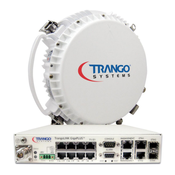
Trango Systems TrangoLINK GigaPlus User Manual (255 pages)
6-40 GHz Split Architecture High Capacity Point-to-Point Microwave Backhaul System
Brand:
Trango Systems
| Category:
Network Hardware
| Size: 5.16 MB
Table of Contents
User Manual
1
Information to User
2
Table of Contents
3
Tables
10
Figures
11
Revision History
14
Preface
15
Table 1: Trangolink
15
Reference Conventions
16
Warranty Information
16
Contacting Trango Technical Support
16
Standards Compliance
17
1.0 Product Description
18
Overview
18
Figure 1 IDU Functional Block Diagram
18
Figure 2 ODU Functional Block Diagram
19
Ports and Indicators - Indoor Unit
20
Figure 3 Front Panel of Gigaplus IDU
20
Location of Serial No. and out of Band MAC Address
23
Ports and Indicators - Outdoor Unit
23
Figure 4 Side of IDU (Shows Where MAC Address Can be Found)
23
Figure 5 Outdoor Unit Connectors/Indicators (HP Model)
23
Figure 6 Polarization Indicator
24
Antenna Connection
25
Remote Mounting
25
Combiners for Antenna Sharing
25
Figure 7 ODU Label
25
Power Supply
26
Table 2 Combiner Cross Reference
26
Key Features
27
Flexible Interfaces and Form Factor
27
Traffic Capacity
27
Industry Leading System Gain
28
Figure 8 LDPC Vs. Reed-Solomon
28
Full Licensed Band Frequency and T/R Spacing Support
29
Table 3 Gigaplus Band and T/R Spacing Options
29
Channel Sizes from 3.5 Mhz to 80 Mhz
30
Adaptive Coding and Modulation
30
Figure 9 Adaptive Coding and Modulation (ACM)
30
Link Protection through 1+1 Hot Standby
31
2.0 Wireless Operation Detail
32
Channel Bandwidth
32
Modulation
32
Mean Squared Error (MSE)
32
Table 4 MSE Expected and Maximum Values
33
Adaptive Coding and Modulation (ACM)
34
Table 5 ACM Threshold Table
35
Wireless Link Capacity
37
Table 6 Max Link Capacity (Mbps) for Non-ACM Speed Settings
37
Automatic Transmit Power Control (ATPC)
38
ATPC Max Power & Step Size
38
Transmitter Maximum Power Output
38
Transmitter Minimum Power Output
39
Table 7 Maximum Set Power Levels by Band and Modulation
39
Table 8 Minimum TX Set Power by Band
39
Receiver Maximum Input
40
Table 9 Max Receive Level Input
40
3.0 Network Operation Detail
41
1+0 Non-Protected Link Configuration
41
Figure 10 1+0 Setup
41
1+1 Hot Standby Protected Link Configuration
42
Figure 11 1+1 Setup
42
Hardware Triggered Failover
43
Table 10 Failover Events
43
Software Triggered Failover
44
User Triggered (Manual) Failover
44
Rapid Port Shutdown (RPS)
45
VLAN Tagging
45
Port Mapping (802.1Q)
46
Q in Q/Double Tagging and Smart_Mode
46
Quality of Service (Qos) (802.1P and Diffserv)
47
Port Priority
48
Port Rate Limiting (Ingress)
48
Egress Margin
48
4.0 Link Management
50
Overview
50
Graphical User Interface (Web Browser)
51
Table 11 Default Login Passwords
51
Figure 12 Web Browser Login
51
Figure 13 System Status Version Page
52
Command Line Interface (CLI) Using SSH, Telnet or Console
54
Changing Password
56
Console Port
57
Simple Network Management Protocol (SNMP)
57
Figure 14 Console Port Setting
57
Common Objects for Monitoring and Control
58
Firmware Upgrade
59
Upgrade Procedure -TFTP
60
Figure 15 Windows Start & Telnet
60
Upgrade Procedure -FTP
62
Capacity Upgrades
64
Figure 16 Capacity Upgrade in Link Setup Page
64
5.0 Link Planning
65
Frequency/Path Planning
65
Site Selection
65
Licensing
65
6.0 Installation
66
Safety
66
Installation Process
69
Preparing for Installation
69
Tools
69
Grounding Overview
70
Figure 17 Site Based Grounding Diagram
70
Power Supply Installation
71
Antenna Installation
72
Install the IDU
72
Table 12 Recommended Torque
72
Figure 18 IDU with Rack Ears Installed
72
Connecting Power
73
Figure 19 Power Connection on Front Panel
73
Figure 20 -48 VDC Power Connector Wiring
73
Ferrite Installation
74
Figure 21 Ferrite
74
Figure 22 Ferrite Installed
74
1+1 Hot Standby IDU Installation
75
Figure 23 1+1 Hot Standby (Idus) with CBLDAT-RIU3
75
HP ODU Installation on Antenna
76
Figure 24 Antenna to HP ODU Slip Fit Waveguide Connection
76
Figure 25 Polarization Indication
77
Figure 26 Latch
77
IF Cable Installation
78
Figure 27 Right Angle N-Connector Mount
79
Weather Proofing Cabling
80
Figure 28 Weather Proofing of Cable
80
Figure 29 Complete Weather Proofing of Cable
80
1+1 Hot Standby ODU Installation
81
Figure 30 Odus on SMC Combiner (1+1)
81
7.0 Link Configuration
82
Web Based Configuration
83
Web Based 1+0 Setup
83
Figure 31 Web Interface Login
83
Figure 32 Web Login with Password
83
Figure 33 System Information Page (View Mode)
84
Figure 34 System Information Page (Config Mode)
85
Figure 35 IP Configuration Page
86
Figure 36 Link Setup Page
87
Web Based 1+1 Setup
88
Figure 37 Failover Mode Set
88
Adaptive Coding and Modulation (ACM) (Optional)
90
Figure 38 ACM Setup
90
Automatic Transmit Power Control (ATPC) (Optional)
91
Alarms, RPS and Telnet/Tftp Daemons
91
Figure 39 ATPC Setup/ RPS /Telnetd/ Tftpd/Alarms
92
Figure 40 Threshold Setup Page
93
Ethernet Configuration
94
Figure 41 Ethernet Setup Page
95
Figure 42 Qos Setup Page for Strict Mode
96
Figure 43 Qos Setup Page for WRR Mode
98
Status Monitoring Overview
99
Figure 44 SNMP Setup Page
99
Link Status
100
Figure 45 Link Status Page
101
Figure 46 Link Test Page
102
Ethernet Statistics
103
Figure 47 Ethernet Statistics Page
103
T1/E1 Statistics
104
Figure 48 TDM (T1/E1) Statistics Page
104
RF Statistics
105
Figure 49 RF Statistics Page
105
Diagnostic Options
107
Figure 50 Diagnostic Options
108
Figure 51 Loopback Auto Page
109
Figure 52 Status Display Page
110
System Log
111
Figure 53 Status Compare Result Page
111
Config View
112
Figure 54 System Log
112
Figure 55 Config View
113
Password Settings
114
Other Settings
114
Figure 56 Password Settings
114
Figure 57 Other Settings
115
Command Line Interface (CLI) Based Configuration
116
CLI Based 1+0 Configuration
116
CLI Based 1+1 Hot Standby Configuration
122
Antenna Alignment
123
Figure 58 BNC Connector for RSSI Voltage
123
Table 13 RSSI to Voltage Conversion
124
CLI Common Task Reference
125
Setting up the In-Band-Management (IBM)
125
Capacity License Activation
128
Automatic Transmit Power Control (ATPC) Configuration (Optional)
128
Check Ethernet and RF Port Statistics
129
Enable Traps (Optional)
131
8.0 Troubleshooting
133
Symptom: no Link (Lock = 0 During Linktest)
133
MSE Is too High And/Or Bit Errors Are Showing When Running Linktest
133
Receive Signal Level Is too Low
134
RF Link Is Good but Packet Loss Is Occurring
135
No Direct Management Using out of Band Port
135
No Radio Management Connection over the Link
136
T1/E1 Ports Not Passing Traffic
136
Appendix A - Command Line Interface Reference
137
Command Keying Overview
137
Key Functions
137
Different Node Levels
138
View Node
138
Config Node
140
Debug Node
145
Individual Command Details
146
Acm
146
Alarm
147
Atpc
148
Ber
149
Bootimage
149
Cableloss
150
Config
151
Custom_Profile
153
Datapath
153
Datapattern
154
Date
155
Debug
155
Default_Opmode
156
Diagnostics
157
Egress_Margin
157
Eth_Info
158
Failover
159
Fanctrl
160
Freq
161
Freq_Duplex
161
Ftp
162
Help
163
Guard_Time
164
Httpd
165
Ibm
165
Ipconfig
166
License
167
Link_History
168
Linktest
168
Loglevel
169
Loopback
170
Model
171
Mse
171
Oduled
172
Odupower
172
Odurxagc
173
Opmode
174
Passwd
175
Port
175
Power
177
Prompt
178
Qos
178
Reboot
180
Reload
181
Remark
181
Reset
182
Rps
183
Rssi
184
Siglevel
184
Snmpd
186
Speed
187
Status
191
Sync
192
Sync_State
192
Sysinfo
193
Syslog
194
Targetrssi
195
Tdm
195
Telnetd
196
Temp
196
Tftpd
197
Threshold
198
Trap
199
Uptime
200
Utype
201
Utype_Switch
202
Version
203
Voltage
203
Appendix B - Product Specifications
205
Dimensions and Weight
205
Environmental
205
Emissions
205
Reliability
206
Electromagnetic Compliance
206
Wireless Compliance
206
Wireless Parameters
207
Transmitter Power
207
1+1 Hot Standby Link Protection
209
Specification
209
Power
209
User Interfaces
209
Ethernet Parameters
210
T1/E1 Parameters
210
Appendix C - Cable Wiring
211
Ethernet Cabling
211
Figure 59 EIA/TIA 568A Straight through
211
Figure 60 EIA/TIA 568B Cross-Over
211
T1/E1 Cabling
212
Table 14 T1/E1 Cable Wiring
212
DB9 Port Interfaces
213
DB9 Console Cable Pin-Outs
213
Table 15 Console Cable Pin-Outs
213
Figure 61 Console Cable Connector
213
DB9 Alarm Port Pin-Outs
214
Table 16 Alarm Port Pin Functions
214
Figure 62 Alarm Port Pin Identification
214
Appendix D - MIB OID Listing
215
Appendix E - Part Numbers
229
Gigaplus HP ODU Sub-Bands/Tuning Ranges
229
Accessories
241
Appendix F – Link Install and Commissioning Logs
242
Site Information
243
Appendix G – Declaration of Conformity
253
Glossary
254
Advertisement
Advertisement
Related Products
Trango Systems TrangoLINK-45TM
Trango Systems TrangoLink-45
Trango Systems TrangoLink-10
Trango Systems TrangoLINK APEX 18GHz
Trango Systems Altum AC 600
Trango Systems Categories
Network Router
Antenna
Wireless Access Point
Microphone system
Network Hardware
More Trango Systems Manuals
Login
Sign In
OR
Sign in with Facebook
Sign in with Google
Upload manual
Upload from disk
Upload from URL