Sign In
Upload
Manuals
Brands
Mitsubishi Manuals
Servo Drives
MR-JE-100A
Mitsubishi MR-JE-100A Manuals
Manuals and User Guides for Mitsubishi MR-JE-100A. We have
2
Mitsubishi MR-JE-100A manuals available for free PDF download: Instruction Manual
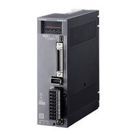
Mitsubishi MR-JE-100A Instruction Manual (396 pages)
MR-JE series General-Purpose Interface AC Servo. POSITIONING MODE
Brand:
Mitsubishi
| Category:
Amplifier
| Size: 2.69 MB
Table of Contents
Safety Instructions
2
Table of Contents
10
1 Functions and Configuration
14
For Proper Use of the Positioning Mode
14
Positioning Mode Specification List
15
Function List
17
Configuration Including Peripheral Equipment
20
2 Signals and Wiring
22
I/O Signal Connection Example
24
Connectors and Pin Assignment
28
Signal (Device) Explanations
32
Analog Override
44
Internal Connection Diagram
46
Power-On Sequence
48
3 Display and Operation Sections
50
Mr-Je-_A
50
Display Flowchart
50
Status Display Mode
52
Diagnostic Mode
57
Alarm Mode
60
Point Table Setting
62
Parameter Mode
66
External I/O Signal Display
68
Output Signal (DO) Forced Output
69
Single-Step Feed
70
Teaching Function
72
4 How to Use the Point Table
74
Startup
75
Power on and off Procedures
75
Stop
76
Test Operation
77
Parameter Setting
78
Point Table Setting
79
Actual Operation
79
Troubleshooting at Start-Up
79
Automatic Operation Mode
81
Automatic Operation Using Point Table
86
Manual Operation Mode
116
JOG Operation
116
Manual Pulse Generator Operation
118
Home Position Return Mode
119
Outline of Home Position Return
120
Dog Type Home Position Return
122
Count Type Home Position Return
124
Data Set Type Home Position Return
126
Stopper Type Home Position Return
127
Home Position Ignorance (Servo-On Position as Home Position)
129
Dog Type Rear End Reference Home Position Return
130
Count Type Front End Reference Home Position Return
132
Dog Cradle Type Home Position Return
134
Dog Type Last Z-Phase Reference Home Position Return
135
Dog Type Front End Reference Home Position Return Type
137
Dogless Z-Phase Reference Home Position Return Type
139
Automatic Retract Function Used for the Home Position Return
140
Automatic Positioning to Home Position Function
141
Roll Feed Mode Using the Roll Feed Display Function
142
Point Table Setting Method
143
Setting Procedure
143
Detailed Setting Window
145
5 How to Use the Program
146
Startup
146
Power on and off Procedures
147
Stop
147
Test Operation
148
Parameter Setting
149
Actual Operation
150
Troubleshooting at Start-Up
150
Program Operation Method
151
Program Language
152
Basic Settings of Signals and Parameters
175
Timing Chart of the Program Operation
177
Manual Operation Mode
179
JOG Operation
179
Manual Pulse Generator Operation
180
Home Position Return Mode
182
Outline of Home Position Return
182
Dog Type Home Position Return
185
Count Type Home Position Return
187
Data Set Type Home Position Return
189
Stopper Type Home Position Return
190
Home Position Ignorance (Servo-On Position as Home Position)
191
Dog Type Rear End Reference Home Position Return
192
Count Type Front End Reference Home Position Return
194
Dog Cradle Type Home Position Return
196
Dog Type Last Z-Phase Reference Home Position Return
198
Dog Type Front End Reference Home Position Return Type
200
Dogless Z-Phase Reference Home Position Return Type
202
Automatic Retract Function Used for the Home Position Return
203
Serial Communication Operation
204
Positioning Operation Using the Program
204
Multi-Drop Method (RS-422 Communication)
205
Group Specification
206
Incremental Value Command Method
208
Roll Feed Mode Using the Roll Feed Display Function
209
Program Setting Method
210
Setting Procedure
210
Window for Program Edit
211
Indirect Addressing Window
212
6 Application of Functions
214
Simple Cam Function
214
Outline of Simple Cam Function
214
Simple Cam Function Block
215
Simple Cam Specification List
216
Control of Simple Cam Function
217
Operation in Combination with the Simple Cam
218
Setting List
220
Data to be Used with Simple Cam Function
221
Function Block Diagram for Displaying State of Simple Cam Control
239
Operation
240
Cam No. Setting Method
250
Stop Operation of Cam Control
251
Restart Operation of Cam Control
253
Cam Axis Position at Cam Control Switching
254
Clutch
261
Cam Position Compensation Target Position
263
Cam Position Compensation Time Constant
264
Mark Detection
265
Current Position Latch Function
265
Interrupt Positioning Function
271
7 Parameters
276
Parameter List
276
Gain/Filter Setting Parameters ([Pr. PB_ _ ])
278
Basic Setting Parameters ([Pr. PA
290
Gain/Filter Setting Parameters ([Pr. PB
300
Extension Setting Parameters ([Pr. PC
312
I/O Setting Parameters ([Pr. PD_ _ ])
322
Extension Setting 2 Parameters ([Pr. PE_ _ ])
332
Extension Setting 3 Parameters ([Pr. PF
333
Positioning Control Parameters ([Pr. PT
335
How to Set the Electronic Gear
344
Software Limit
345
Stop Method for LSP (Forward Rotation Stroke End) off or LSN (Reverse Rotation Stroke End) off
346
Stop Method at Software Limit Detection
347
8 Troubleshooting
348
Explanations of the Lists
348
Alarm List
349
Warning List
353
9 Options and Peripheral Equipment
356
MR-HDP01 Manual Pulse Generator
357
10 Communication Function (Mitsubishi Electric General-Purpose Ac Servo Protocol)
360
Command and Data No. List
360
Reading Command
361
Writing Commands
369
Detailed Explanations of Commands
373
External I/O Signal Status (DIO Diagnosis)
373
Input Device On/Off
378
Input Device On/Off (for Test Operation)
379
Test Operation Mode
380
Output Signal Pin On/Off (Output Signal (DO) Forced Output)
382
Point Table
383
Advertisement
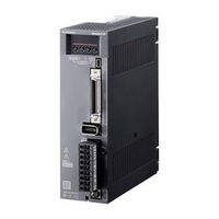
Mitsubishi MR-JE-100A Instruction Manual (348 pages)
servo amplifiers
Brand:
Mitsubishi
| Category:
Servo Drives
| Size: 2.81 MB
Table of Contents
Table of Contents
10
1 Functions and Configuration
16
Summary
16
Function Block Diagram
17
Servo Amplifier Standard Specifications
19
Combinations of Servo Amplifiers and Servo Motors
21
Function List
22
Model Designation
24
Structure
25
Parts Identification
25
Configuration Including Peripheral Equipment
27
2 Installation
30
Installation Direction and Clearances
31
Keep out Foreign Materials
32
Encoder Cable Stress
33
Inspection Items
33
Parts Having Service Lives
34
3 Signals and Wiring
36
Input Power Supply Circuit
37
I/O Signal Connection Example
42
Position Control Mode
42
Speed Control Mode
47
Torque Control Mode
49
Explanation of Power Supply System
51
Signal Explanations
51
Power-On Sequence
52
Wiring CNP1 and CNP2
53
Connectors and Pin Assignment
55
Signal (Device) Explanations
58
Detailed Explanation of Signals
66
Position Control Mode
66
Speed Control Mode
71
Torque Control Mode
73
Position/Speed Control Switching Mode
76
Speed/Torque Control Switching Mode
78
Torque/Position Control Switching Mode
80
Forced Stop Deceleration Function
81
Base Circuit Shut-Off Delay Time Function
83
Vertical Axis Freefall Prevention Function
84
Residual Risks of the Forced Stop Function (EM2)
84
Alarm Occurrence Timing Chart
85
When You Use the Forced Stop Deceleration Function
85
When You Do Not Use the Forced Stop Deceleration Function
86
Interfaces
87
Internal Connection Diagram
87
Detailed Explanation of Interfaces
89
Source I/O Interfaces
93
Servo Motor with an Electromagnetic Brake
95
Safety Precautions
95
Timing Chart
97
Grounding
100
4 Startup
102
Switching Power on for the First Time
102
Startup Procedure
102
Wiring Check
103
Surrounding Environment
104
Startup in Position Control Mode
105
Power on and off Procedures
105
Stop
105
Test Operation
106
Parameter Setting
107
Actual Operation
107
Trouble at Start-Up
108
Startup in Speed Control Mode
110
Power on and off Procedures
110
Stop
110
Test Operation
111
Parameter Setting
112
Actual Operation
113
Trouble at Start-Up
113
Startup in Torque Control Mode
114
Power on and off Procedures
114
Stop
114
Test Operation
115
Parameter Setting
116
Actual Operation
116
Trouble at Start-Up
117
Display and Operation Sections
118
Display Flowchart
119
Status Display Mode
120
Diagnostic Mode
124
Alarm Mode
126
Parameter Mode
127
External I/O Signal Display
129
Output Signal (DO) Forced Output
132
Test Operation Mode
133
5 Parameters
138
Parameter List
138
I/O Setting Parameters ([Pr. PD_ _ ])
142
Basic Setting Parameters ([Pr. PA
145
Gain/Filter Setting Parameters ([Pr. PB
154
Extension Setting Parameters ([Pr. PC
165
I/O Setting Parameters ([Pr. PD
176
6 NORMAL GAIN ADJUSTMENT 6- 1 to
184
Different Adjustment Methods
184
Adjustment Using MR Configurator2
185
One-Touch Tuning
186
One-Touch Tuning Flowchart
186
Display Transition and Operation Procedure of One-Touch Tuning
188
Caution for One-Touch Tuning
196
Auto Tuning
197
Auto Tuning Mode
197
Auto Tuning Mode Basis
198
Adjustment Procedure by Auto Tuning
199
Response Level Setting in Auto Tuning Mode
200
Manual Mode
201
Gain Adjustment Mode
205
7 Special Adjustment Functions
208
Filter Setting
208
Machine Resonance Suppression Filter
208
Adaptive Filter II
211
Shaft Resonance Suppression Filter
213
Low-Pass Filter
214
Command Notch Filter
219
Gain Switching Function
220
Function Block Diagram
221
Parameter
222
Gain Switching Procedure
224
Tough Drive Function
228
Vibration Tough Drive Function
228
Instantaneous Power Failure Tough Drive Function
230
Model Adaptive Control Disabled
234
8 Troubleshooting
236
Explanations of the Lists
236
Alarm List
237
Warning List
241
9 Dimensions
244
Servo Amplifier
244
Connector
247
10 Characteristics
250
Overload Protection Characteristics
250
Power Supply Capacity and Generated Loss
251
Dynamic Brake Characteristics
253
Dynamic Brake Operation
253
Permissible Load to Motor Inertia When the Dynamic Brake Is Used
254
Cable Bending Life
255
Inrush Current at Power-On
255
11 Options and Peripheral Equipment
256
Cable/Connector Sets
256
Combinations of Cable/Connector Sets
257
Regenerative Option
259
Combination and Regenerative Power
259
Selection of Regenerative Option
260
Selection of Regenerative Option
262
Dimensions
266
Junction Terminal Block MR-TB50
268
MR Configurator2
270
Specifications
270
System Requirements
270
Precautions for Using USB Communication Function
272
Selection Example of Wires
273
Molded-Case Circuit Breakers, Fuses, Magnetic Contactors
274
Power Factor Improving AC Reactor
275
Relay (Recommended)
276
Noise Reduction Techniques
277
Earth-Leakage Current Breaker
283
EMC Filter (Recommended)
285
12 Communication Function (Mitsubishi General-Purpose Ac Servo Protocol)
288
Structure
288
Configuration Diagram
288
Precautions for Using RS422/USB Communication Function
289
Communication Specifications
290
Outline of Communication
290
Parameter Setting
290
Protocol
291
Transmission Data Configuration
291
Character Codes
292
Error Codes
293
Checksum
293
Time-Out Processing
293
Retry Processing
294
Initialization
294
Communication Procedure Example
295
Command and Data No. List
296
Reading Command
296
Writing Commands
300
Detailed Explanations of Commands
302
Data Processing
302
Status Display Mode
304
Parameter
305
External I/O Signal Status (DIO Diagnosis)
309
Input Device On/Off
312
Disabling/Enabling I/O Devices (DIO)
312
Input Devices On/Off (Test Operation)
313
Test Operation Mode
314
Output Signal Pin On/Off (Output Signal (DO) Forced Output)
317
Alarm History
318
Current Alarm
319
Software Version
320
Appendix
322
App. 1 Peripheral Equipment Manufacturer (for Reference)
322
App. 2 Compliance with Global Standards
322
App. 3 Analog Monitor
332
App. 4 Low-Voltage Directive
335
App. 5 Using HF-KN Series and HF-SN Series Servo Motors
336
App. 6 When Turning on or off the Input Power Supply with DC Power Supply
338
Advertisement
Related Products
Mitsubishi MR-JE series
Mitsubishi MR-JE-10A
Mitsubishi MR-JE-20A
Mitsubishi MR-JE-200A
Mitsubishi MR-JE-300A
Mitsubishi MR-JE-40A
Mitsubishi MR-JE-70A
Mitsubishi MELDAS HS Series
Mitsubishi MELSERVO-SO
Mitsubishi MR-JE-10B
Mitsubishi Categories
Air Conditioner
Controller
Projector
Automobile
Engine
More Mitsubishi Manuals
Login
Sign In
OR
Sign in with Facebook
Sign in with Google
Upload manual
Upload from disk
Upload from URL