ICOM IC-9100 Manuals
Manuals and User Guides for ICOM IC-9100. We have 5 ICOM IC-9100 manuals available for free PDF download: Instruction Manual, Service Manual, Overview, Reference Manual

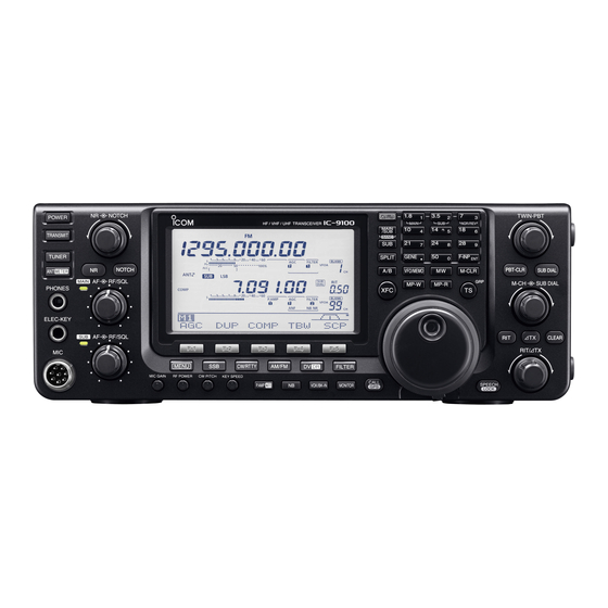
Icom IC-9100 Instruction Manual (212 pages)
HF/VHF/UHF Transceiver
Brand: Icom
|
Category: Transceiver
|
Size: 20 MB
Table of Contents
-
Features2
-
-
Notch Switch11
-
Front Panel12
-
Menu Switch12
-
Sub Switch15
-
Clear Switch18
-
Main Dial18
-
-
Rear Panel20
-
-
Grounding31
-
Antenna SWR32
-
Grounding33
-
-
-
Number Style62
-
Rise Time63
-
Keyr Type64
-
RIT Function78
-
Preamplifier80
-
Attenuator80
-
AGC Function81
-
NB Set Mode85
-
VOX Function87
-
TX Function90
-
Calling CQ110
-
GPS Operation130
-
Add a GPS Memory136
-
My Position141
-
Manual Position141
-
Position Format141
-
GPS Set Mode141
-
Alarm Indication142
-
Alarm Area 1/2142
-
GPS TX Mode143
-
GPS Sentence143
-
Unproto Address143
-
Data Extension144
-
Time Stamp144
-
GPS-A Symbol144
-
Ssid144
-
Comment145
-
GPS-A Opration146
-
Memory Operation147
-
Memory Clearing150
-
Scans154
-
Scan Types154
-
Scan Set Mode156
-
Scan Speed156
-
Scan Resume156
-
Main Dial (Scan)156
-
Mode Select Scan159
-
Reverse Tracking163
-
Normal Tracking163
-
Antenna Tuner168
-
Tuner Operation168
-
Manual Tuning168
-
AH-4 Operation169
-
LCD Backlight170
-
Beep Level170
-
Band Edge Beep170
-
User Band Edge171
-
Time out Timer171
-
PTT Lock171
-
Quick Split171
-
DUP Offset172
-
Speech S-Level173
-
AFC Limit173
-
Notch SW174
-
CW Normal Side174
-
EXT-SP Separate175
-
External Keypad176
-
USB Audio SQL176
-
Data MOD176
-
CI-V Baud Rate176
-
GPS out177
-
RTTY Decode Baud177
-
Ref Adjust177
-
Connections180
-
Maintenance186
-
Troubleshooting186
-
Fuse Replacement189
-
Data Cloning191
-
Control Command192
-
Data Format192
-
Command Table193
-
Operating Mode199
-
Specifications206
-
Options208
Advertisement
Icom IC-9100 Instruction Manual (212 pages)
HF/VHF/UHF TRANSCEIVER
Brand: Icom
|
Category: Transceiver
|
Size: 42 MB
Table of Contents
-
-
Front Panel10
-
Rear Panel19
-
LCD Display24
-
-
D D1 Display28
-
D D2 Display28
-
-
-
Grounding31
-
-
D Rear Panel33
-
-
-
D Rear Panel34
-
Microphones39
-
D Hm-3639
-
-
-
-
Operating CW57
-
-
Keyer Type64
-
-
-
RIT Function78
-
Preamplifier80
-
Attenuator80
-
AGC Function81
-
-
VOX Function87
-
TX Function90
-
-
-
Calling CQ110
-
-
-
GPS Operation130
-
GPS Set Mode141
-
Unproto Address143
-
GPS-A Operation146
-
D GPS-A Function146
-
-
-
Memory Operation
147-
Memory Clearing150
-
Scans
154-
Scan Types154
-
Preparation155
-
Scan Set Mode156
-
Scan Speed156
-
-
-
Satellite Notes162
-
-
Satellite Memory164
-
Preparation165
-
Set Mode
170 -
-
Connections180
-
-
Maintenance
186-
Troubleshooting186
-
D Scanning187
-
D Display187
-
Fuse Replacement189
-
-
D Partial Reset190
-
D All Reset190
-
-
Data Cloning191
-
-
Control Command
192 -
Specifications
206-
General206
-
Transmitter206
-
Receiver207
-
Antenna Tuner207
-
-
Options
208

Icom IC-9100 Service Manual (163 pages)
HF/VHF/UHF TRANSCEIVER
Brand: Icom
|
Category: Transceiver
|
Size: 17 MB
Table of Contents
-
-
Main Unit47
-
Connect Unit57
-
Rf-A Unit66
-
Rf-B Unit69
-
Pa-A Unit75
-
Pa-B Unit79
-
Ctrl Unit83
-
Network Unit85
-
Display Unit86
-
MIC Unit92
-
-
Pll Unit97
-
Front Unit127
-
-
Advertisement

Icom IC-9100 Reference Manual (13 pages)
Tips for the USB port settings
Brand: Icom
|
Category: Transceiver
|
Size: 1 MB
Table of Contents

ICOM IC-9100 Overview (16 pages)
Brand: ICOM
|
Category: Transceiver
|
Size: 0 MB
Advertisement