Sign In
Upload
Manuals
Brands
B&R Manuals
Touch Panel
Panel PC 2100
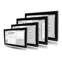
User Manuals: B&R Panel PC 2100 Industrial Touchscreen
Manuals and User Guides for B&R Panel PC 2100 Industrial Touchscreen. We have
4
B&R Panel PC 2100 Industrial Touchscreen manuals available for free PDF download: User Manual
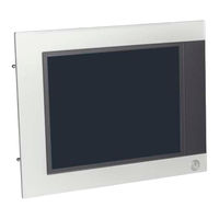
B&R Panel PC 2100 User Manual (357 pages)
Brand:
B&R
| Category:
Touch Panel
| Size: 13 MB
Table of Contents
Table of Contents
4
General Information
11
Manual History
11
Safety Guidelines
13
Intended Use
13
Protection against Electrostatic Discharge
13
Packaging
13
Guidelines for Proper ESD Handling
13
Policies and Procedures
13
Transport and Storage
14
Installation
14
Operation
14
Protection against Touching Electrical Parts
14
Environmental Conditions - Dust, Moisture, Corrosive Gases
14
Viruses and Dangerous Programs
15
Environmentally Friendly Disposal
15
Separation of Materials
15
Security Concept
15
Third-Party Software Updates
15
Administrator Accounts
15
Organization of Notices
16
Guidelines
16
Overview
17
Technical Data
20
Introduction
20
About this User's Manual
20
Description of Individual Modules
20
Ap9X3 Panels
20
AP1000 Panels
20
System Units
21
System Components / Configuration
21
Configuration
21
Complete System
23
Mechanical Properties
23
Dimensions
23
Installation Diagrams
26
Spacing for Air Circulation
29
Mounting Orientations
30
Weight Specifications
31
Environmental Characteristics
32
Temperature Specifications
32
Humidity
40
Vibration
41
Shock
41
Protection
41
Electrical Characteristics
42
VDC Power Supply
42
Power Calculation
43
Block Diagrams
45
Device Interfaces and Slots
48
Device Interfaces - Overview
48
VDC Power Supply
49
Ethernet 1 Interface (ETH1)
51
Ethernet 2 Interface (ETH2)
51
USB Interfaces
52
Cfast Slot
54
Power Button
54
Reset Button
54
LED Status Indicators
55
IF Option Slot (IF1, Ifx)
56
Features of AP1000 Panels
57
Slide-In Labels
57
Key and LED Configuration
58
USB Interface
62
Mounting Compatibility
63
Compatibility Overview
63
Compatibility Details
65
Individual Components
73
Ap9X3 Panels
73
5Ap923.1215-00
73
5Ap923.1505-00
75
5Ap923.1906-00
77
5Ap933.156B-00
80
5Ap933.185B-00
83
5Ap933.215C-00
86
5Ap933.240C-00
89
AP1000 Panels
92
5Ap1120.0573-000
92
5Ap1151.0573-000
95
5Ap1120.0702-000
98
5Ap1130.0702-000
100
5Ap1120.101E-000
102
5Ap1130.101E-000
104
5Ap1120.1043-000
106
5Ap1180.1043-000
109
5Ap1181.1043-000
112
5Ap1182.1043-000
115
5Ap1120.1214-000
118
5Ap1120.121E-000
121
5Ap1130.121E-000
123
5Ap1120.1505-000
125
5Ap1180.1505-000
128
5Ap1181.1505-000
131
5Ap1120.156B-000
135
5Ap1130.156C-000
137
5Ap1130.185C-000
139
5Ap1120.1906-000
141
System Units
144
5Ppc2100.Byxx-000
144
Cfast Cards
147
General Information
147
Basic Information
147
5Cfast.XXXX-00
149
5Cfast.XXXX-10
152
Interface Options
158
5Accif01.Fpcc-000
158
5Accif01.Fpcs-000
166
5Accif01.Fplk-000
173
5Accif01.Fpls-000
178
5Accif01.Fpls-001
183
5Accif01.Fpsc-000
188
5Accif01.Fpsc-001
194
5Accif01.Fss0-000
201
5Accif01.Ican-000
206
Commissioning
210
Installation
210
Important Information Concerning Installation/Commissioning
210
Installing a Panel PC with an Ap9X3 Panel
212
Mounting an Automation Panel 1000 with Retaining Clips
214
Mounting an Automation Panel 1000 with Clamping Blocks
216
Installation Information for Individual Components
218
Replacing the System Unit
219
Installation the 4-Port USB Hub
220
Connecting to the Electrical Grid
221
Installing the DC Power Cable
221
Wiring
221
Connecting the Power Supply to a B&R Device
222
Functional Ground - Grounding Concept
222
Cable Connections
224
Switching on the Device for the First Time
225
General Information before Switching on the Device
225
Switching on the Device
225
General Instructions for Performing Temperature Testing
226
Procedure
226
Evaluating Temperatures in Windows Operating Systems
226
Evaluating with the B&R Control Center
226
Evaluating with the Burnintest Tool from Passmark
227
Evaluating Temperatures in Non-Windows Operating Systems
229
Evaluating the Measurement Results
229
Touch Screen Calibration
230
Single-Touch (Analog Resistive)
230
Windows 10 Iot Enterprise 2016 LTSB
230
Windows 10 Iot Enterprise 2015 LTSB
230
Windows Embedded 8.1 Industry Pro
230
Windows 7 Professional / Ultimate
230
Windows Embedded Standard 7 Embedded / Premium
230
Multi-Touch (Projected Capacitive - PCT)
230
Windows 7 Professional / Ultimate
231
Windows Embedded Standard 7 Premium
231
Adjusting the Display Brightness
232
Known Problems / Issues
233
Software
234
BIOS Options
234
General Information
234
BIOS Setup and Boot Procedure
234
BIOS Default Settings
235
BIOS Setup Keys
235
Main
236
System Information
237
Advanced
238
OEM Features
239
CPU Configuration
251
Graphics (IGD) Configuration
253
Lan
255
PCI Express Configuration
257
USB Configuration
259
SATA Configuration
260
Miscellaneous Configuration
261
Thermal Configuration
262
Security
263
Boot
264
Boot Device Priority
265
Boot Configuration
266
Exit
268
Allocation of Resources
269
RAM Address Assignments
269
I/O Address Assignments
269
Interrupt Assignments in PIC Mode
269
Interrupt Assignments in APIC Mode
270
Upgrade Information
271
BIOS Upgrade
271
Important Information
271
Procedure in EFI Shell
272
Upgrading the Firmware on the Panel PC 2100
273
Procedure in Windows (B&R Control Center)
273
Procedure in EFI Shell
273
Multi-Touch Drivers
274
Windows 10 Iot Enterprise 2016 LTSB
275
General Information
275
PPC2100 - Order Data
275
PPC2100 - Overview
275
Features
275
Installation
275
Drivers
275
Activation
276
Issues and Limitations
276
Supported Display Resolutions
276
Windows 10 Iot Enterprise 2015 LTSB
277
General Information
277
PPC2100 - Order Data
277
Overview
277
Features
277
Installation
277
Drivers
277
Activation
278
Recovery DVD - Content of Delivery
278
Issues and Limitations
279
Supported Display Resolutions
279
Windows Embedded 8.1 Industry Pro
280
General Information
280
Order Data
280
Overview
280
Features
280
Installation
281
Drivers
281
Activation
281
Contents of the Recovery DVD
282
Lockdown Features
282
Supported Display Resolutions
282
Windows 7
283
General Information
283
Order Data
283
Overview
284
Installation
284
Drivers
284
Issues and Limitations
285
Supported Display Resolutions
285
Windows Embedded Standard 7
286
General Information
286
Order Data
286
Overview
286
Features
286
Installation
287
Drivers
287
Issues and Limitations
287
Supported Display Resolutions
287
Automation Runtime
288
General Information
288
Order Data
288
Automation Runtime Windows (Arwin)
288
Automation Runtime Embedded (Aremb)
289
Technology Guarding
289
B&R Hypervisor
290
Mapp Technology
291
B&R Linux 8 (Gnu/Linux)
292
General Information
292
Advertisement
B&R Panel PC 2100 User Manual (299 pages)
Panel mount devices
Brand:
B&R
| Category:
Desktop
| Size: 11 MB
Table of Contents
Publishing Information
2
Table of Contents
3
Introduction
10
Manual History
11
Information about this Document
13
Organization of Notices
13
General Notices
13
Guidelines
13
General Safety Guidelines
14
Intended Use
14
Protection against Electrostatic Discharge
14
Packaging
14
Regulations for Proper ESD Handling
14
Regulations and Measures
15
Transport and Storage
15
Installation
15
Operation
16
Protection against Contact with Electrical Parts
16
Ambient Conditions - Dust, Moisture, Aggressive Gases
16
Programs, Viruses and Malicious Programs
16
Cybersecurity Disclaimer for Products
17
System Overview
18
About this User's Manual
18
Description of Individual Modules
19
System Units
19
Ap9X3 Panels
19
AP1000 Panels
19
Design/Configuration
19
Configuration
20
Order Number Key
22
Overview
23
Technical Data
25
Complete System
25
Mechanical Properties
25
Dimensions
25
Mounting Orientations
28
Spacing for Air Circulation
31
Mounting Orientations
32
Weight Specifications
33
Environmental Properties
34
Temperature Specifications
34
Temperature Monitoring
40
Humidity
42
Vibration
43
Shock
43
Degree of Protection
43
Electrical Properties
44
System Units - Block Diagram
44
Power Calculation
45
System Units
45
Interface Options
45
Cfast Cards
46
Device Interfaces and Slots
47
Device Interfaces - Overview
47
VDC Power Supply
48
Ethernet Interfaces
49
Driver Support
49
USB Interfaces
50
Cfast Slot
51
Power and Reset Buttons
51
LED Status Indicators
52
IF Option Slot(IF1, Ifx)
53
Features of AP1000 Panels
54
Slide-In Labels
54
Key and LED Configuration
55
USB Interface
58
Individual Components
59
System Units
59
5Ppc2100.Byxx-000
59
Order Data
59
Ap9X3 Panels
62
5Ap923.1215-00
62
General Information
62
Temperature/Humidity Diagram
63
5Ap923.1505-00
64
5Ap923.1906-00
66
5Ap933.156B-00
69
5Ap933.185B-00
71
5Ap933.215C-00
73
5Ap933.240C-00
75
AP1000 Panels
78
5Ap1120.0573-000
78
5Ap1151.0573-000
81
5Ap1120.0702-000
84
5Ap1130.0702-000
86
5Ap1130.101D-000
88
5Ap1120.101E-000
90
5Ap1130.101E-000
92
5Ap1120.1043-000
94
5Ap1180.1043-000
96
5Ap1181.1043-000
99
5Ap1182.1043-000
102
5Ap1120.1214-000
105
5Ap1120.121E-000
107
5Ap1130.121E-000
109
5Ap1130.121E-010
111
5Ap1120.1505-000
113
5Ap1180.1505-000
115
5Ap1181.1505-000
117
5Ap1120.156B-000
120
5Ap1130.156C-000
123
5Ap1130.156C-001
125
5Ap1130.185C-000
127
5Ap1120.1906-000
129
Interface Options
132
5Accif01.Fpcc-000
132
Cable Data
134
Terminating Resistor
134
Led Status Indicators
136
5Accif01.Fpcs-000
137
5Accif01.Fplk-000
141
5Accif01.Fpls-000
144
Order Data
144
5Accif01.Fpls-001
147
5Accif01.Fpsc-000
150
Terminating Resistor
153
5Accif01.Fpsc-001
154
Cable Data
157
5Accif01.Fss0-000
159
5Accif01.Ican-000
163
5Accif01.Is00-000
166
Cfast Cards
168
Installation and Wiring
169
Basic Information
169
Installing a Panel PC with an Ap9X3 Panel
171
Installing the Automation Panel 1000 with Retaining Clips
173
Installing the Automation Panel 1000 with Clamping Blocks
175
Installation Information for Individual Components
177
Replacing the System Unit
178
Installing the USB Hub
179
Connecting to the Power Grid
179
Installing the DC Power Cable
179
Wiring
180
Connecting the Power Supply to a B&R Device
180
Grounding Concept - Functional Ground
180
Connecting Cables
182
Commissioning
183
Basic Information
183
Switching on the Device for the First Time
183
General Information before Switching on the Device
183
Switching on the Device
183
General Instructions about the Procedure for Temperature Testing
184
Procedure
184
Evaluating Temperatures in Windows Operating Systems
184
Evaluating with the B&R Control Center
184
Evaluating with the Burnintest Tool from Passmark
185
Evaluating Temperatures in Other Operating Systems
187
Evaluating the Measurement Results
187
Touch Screen Calibration
187
Single-Touch (Analog Resistive)
187
Windows 10 Iot Enterprise 2016 LTSB
187
Windows 10 Iot Enterprise 2015 LTSB
187
Windows Embedded 8.1 Industry Pro
187
Windows 7 Professional / Ultimate
187
Windows Embedded Standard 7 Embedded / Premium
187
Multi-Touch (Projected Capacitive - PCT)
188
Windows 10 Iot Enterprise 2016 LTSB
188
Windows 10 Iot Enterprise 2015 LTSB
188
Windows Embedded 8.1 Industry Pro
188
Windows 7 Professional / Ultimate
188
Windows Embedded Standard 7 Premium
188
Display Brightness Control
188
Known Problems / Characteristics
189
Software
190
BIOS Options
190
General Information
190
BIOS Setup and Start Procedure
190
BIOS Default Settings
190
BIOS Setup Buttons
191
Main
192
System Information
192
Advanced
194
OEM Features
195
Super Io Configuration
196
System Board Features
197
Temperature Values
198
CPU Configuration
202
Cpu Power Management
203
Graphics (IGD) Configuration
204
IGD - LCD Control
205
Lan
206
LAN Configuration
206
Item Specific Help
206
Network Stack
207
PCI Express Configuration
207
USB Configuration
209
SATA Configuration
210
Miscellaneous Configuration
210
Thermal Configuration
211
Security
213
Boot
214
Boot Device Priority
214
Boot Configuration
215
Exit
217
Allocation of Resources
218
RAM Address Assignment
218
I/O Address Assignments
218
Interrupt Assignments in PIC Mode
218
Interrupt Assignments in APIC Mode
219
Upgrade Information
220
BIOS Upgrade
220
Basic Information
220
Procedure in the EFI Shell
221
Upgrading the Firmware on the Panel PC 2100
222
Procedure in Windows (ADI Control Center)
222
Procedure in the EFI Shell
222
Firmware Upgrade with Automation Runtime
222
Multi-Touch Drivers
223
Windows 10 Iot Enterprise 2016 LTSB
224
General Information
224
PPC2100 - Order Data
224
PPC2100 - Overview
224
Features
224
Installation
225
Drivers
225
Activation
225
Characteristics, Limitations
225
Supported Display Resolutions
226
Windows 10 Iot Enterprise 2015 LTSB
227
General Information
227
PPC2100 - Order Data
227
Overview
227
Features
227
Installation
228
Drivers
228
Activation
228
Content of Delivery of the Recovery DVD
229
Characteristics, Limitations
229
Supported Display Resolutions
229
Windows Embedded 8.1 Industry Pro
230
General Information
230
Order Data
230
Overview
230
Features
230
Installation
231
Drivers
231
Activation
231
Content of Delivery of the Recovery DVD
232
Lockdown Features
232
Supported Display Resolutions
232
Windows 7
233
General Information
233
Order Data
233
Overview
233
Installation
233
Drivers
234
Characteristics, Limitations
234
Supported Display Resolutions
234
Windows Embedded Standard 7
235
General Information
235
Order Data
235
Overview
235
Features
235
Installation
236
Drivers
236
Characteristics, Limitations
236
Supported Display Resolutions
236
Automation Runtime
237
General Information
237
Order Data
237
Automation Runtime Windows (Arwin)
237
Automation Runtime Embedded (Aremb)
238
Technology Guarding
238
B&R Hypervisor
239
Mapp Technology
240
Linux for B&R 8 (Gnu/Linux)
241
General Information
241
Order Data
241
Overview
241
Features
241
Installation
242
Drivers
242
Linux for B&R 9 (Gnu/Linux)
243
General Information
243
Order Data
243
Overview
243
B&R Panel PC 2100 User Manual (288 pages)
Built-in devices
Brand:
B&R
| Category:
Touch Panel
| Size: 16 MB
Table of Contents
Table of Contents
3
Chapter 1 General Information
9
Manual History
9
Safety Guidelines
10
Intended Use
10
Protection against Electrostatic Discharge
10
Packaging
10
Guidelines for Proper ESD Handling
10
Policies and Procedures
10
Transport and Storage
11
Installation
11
Operation
11
Protection against Touching Electrical Parts
11
Environmental Conditions - Dust, Moisture, Corrosive Gases
11
Viruses and Dangerous Programs
11
Environmentally Friendly Disposal
12
Separation of Materials
12
Organization of Safety Notices
13
Guidelines
13
Overview
14
Chapter 2 Technical Data
16
Introduction
16
About this User's Manual
16
Description of Individual Modules
16
Display Units Ap9X3
16
AP1000 Display Units
16
System Unit
17
Structure/Configuration
17
Configuration
17
Complete System
19
Mechanical Characteristics
19
Dimensions
19
Installation Diagrams
22
Spacing for Air Circulation
25
Mounting Orientations
26
Weight Specifications
27
Environmental Characteristics
28
Temperature Specifications
28
Humidity
34
Vibration
35
Shock
35
Protection
35
Electrical Characteristics
36
VDC Voltage Supply
36
Power Calculation
37
Block Diagrams
39
Device Interfaces and Slots
42
Device Interfaces - Overview
42
VDC Voltage Supply
43
Ethernet 1 Interface (ETH1)
44
Ethernet 2 Interface (ETH2)
44
USB Interfaces
45
Cfast Slot
46
Power Button
46
Reset Button
46
LED Status Indicators
47
IF Option Slot (IF1, Ifx)
48
Layout of AP1000 Display Units
49
Slide-In Labels
49
Key and LED Configuration
50
USB Interface
53
Mounting Compatibility
54
Compatibility Overview
54
Compatibility Details
56
Individual Components
64
Ap9X3 Display Units
64
5Ap923.1215-00
64
5Ap923.1505-00
66
5Ap923.1906-00
68
5Ap933.156B-00
70
5Ap933.185B-00
72
5Ap933.215C-00
74
5Ap933.240C-00
76
AP1000 Display Units
78
5Ap1120.0573-000
78
5Ap1151.0573-000
80
5Ap1120.0702-000
82
5Ap1120.101E-000
84
5Ap1120.1043-000
86
5Ap1180.1043-000
89
5Ap1181.1043-000
92
5Ap1182.1043-000
95
5Ap1120.1214-000
98
5Ap1120.121E-000
100
5Ap1120.1505-000
102
5Ap1180.1505-000
104
5Ap1120.156B-000
106
5Ap1120.1906-000
108
System Units
111
5Ppc2100.Byxx-000
111
Cfast Cards
114
General Information
114
Basic Information
114
5Cfast.XXXX-00
116
5Cfast.XXXX-10
119
Interface Options
122
5Accif01.Fpcc-000
122
5Accif01.Fplk-000
131
5Accif01.Fpls-000
136
5Accif01.Fpls-001
141
5Accif01.Fpsc-000
146
5Accif01.Fpsc-001
153
5Accif01.Ican-000
160
Chapter 3 Installation
164
Installation
164
Important Installation Information
164
Installation Panel PC with Ap9X3 Display Unit
164
Mounting an Automation Panel 1000 with Retaining Clips
166
Mounting an Automation Panel 1000 with Clamping Blocks
168
Installation Information for Individual Components
170
Replacing the System Unit
171
Connecting to the Power Mains
172
Installing the DC Power Cable
172
Wiring
172
Connecting the Power Supply to a B&R Device
173
Functional Ground - Grounding Concept
174
Cable Connections
175
General Instructions for Performing Temperature Testing
176
Procedure
176
Evaluating Temperatures in Windows Operating Systems
176
Evaluating with the B&R Control Center
176
Evaluating with the Burnintest Tool from Passmark
177
Evaluating Temperatures in Operating Systems Other than Windows
179
Evaluating the Measurement Results
179
Switching on the Device for the First Time
180
General Information before Switching on the Device
180
Switching on the Device
180
Touch Screen Calibration
181
Single-Touch (Analog Resistive)
181
Windows 10 Iot Enterprise 2015 LTSB
181
Windows Embedded 8.1 Industry Pro
181
Windows 7 Professional / Ultimate
181
Windows Embedded Standard 7 Embedded / Premium
181
Multi-Touch (Projected Capacitive - PCT)
181
Windows Embedded Standard 7 Premium
181
Adjusting the Display Brightness
182
Known Problems / Issues
183
Chapter 4 Software
184
BIOS Options
184
General Information
184
BIOS Setup and Boot Procedure
184
BIOS Default Settings
184
BIOS Setup Keys
185
Main
186
System Information
187
Advanced
188
OEM Features
189
CPU Configuration
201
Graphics (IGD) Configuration
203
Lan
205
PCI Express Configuration
206
USB Configuration
208
SATA Configuration
209
Miscellaneous Configuration
210
Thermal Configuration
211
Security
212
Boot
213
Boot Device Priority
214
Boot Configuration
215
Exit
217
Allocation of Resources
218
RAM Address Assignments
218
I/O Address Assignments
218
Interrupt Assignments in PIC Mode
218
Interrupt Assignments in APIC Mode
219
Upgrade Information
220
BIOS Upgrade
220
Important Information
220
The Procedure in the EFI Shell
221
Firmware Upgrade of the Panel PC 2100 of the Automation PC 2100
222
The Procedure in Windows (B&R Control Center)
222
The Procedure in the EFI Shell
222
Windows 10 Iot Enterprise 2015 LTSB
223
General Information
223
PPC2100 - Order Data
223
Overview
223
Features with Win10 Ent 2015 (Windows 10 Iot Enterprise 2015 LTSB)
223
Installation
223
Drivers
223
Activation
224
Contents of the Recovery DVD
224
Special Considerations, Limitations
225
Supported Display Resolutions
225
Windows Embedded 8.1 Industry Pro
226
General Information
226
Order Data
226
Overview
226
Features with Windows Embedded 8.1 Industry Pro (W81Ipro)
226
Installation
227
Drivers
227
Activation
227
Contents of the Recovery DVD
228
Lockdown Features
228
Supported Display Resolutions
228
Windows 7
229
General Information
229
Order Data
229
Overview
230
Installation
230
Drivers
230
Special Considerations, Limitations
230
Supported Display Resolutions
231
Windows Embedded Standard 7
232
General Information
232
Order Data
232
Overview
232
Features with WES7 (Windows Embedded Standard 7)
232
Installation
233
Drivers
233
Special Considerations, Limitations
233
Supported Display Resolutions
233
Automation Runtime
234
General Information
234
Order Data
234
Automation Runtime Windows (Arwin)
234
Automation Runtime Embedded (Aremb)
235
Technology Guarding
235
Debian (Gnu/Linux)
236
General Information
236
Order Data
236
Overview
236
Features
236
Installation
236
Drivers
237
R Automation Device Interface (ADI) - Control Center
238
Functions
238
Installation
239
R Automation Device Interface (ADI) Development Kit
240
R Automation Device Interface (ADI) .NET SDK
242
R Key Editor
244
R KCF Editor
246
HMI Service Center
247
5Swuti.0001-000
247
General Information
247
Order Data
247
Advertisement
B&R Panel PC 2100 User Manual (204 pages)
Brand:
B&R
| Category:
Control Panel
| Size: 6 MB
Table of Contents
Table of Contents
2
1 Introduction
7
Manual History
7
Information about this Document
9
Organization of Safety Notices
9
Guidelines
9
2 General Safety Guidelines
10
Intended Use
10
Protection against Electrostatic Discharge
10
Packaging
10
Regulations for Proper ESD Handling
10
Regulations and Measures
10
Transport and Storage
11
Installation
11
Operation
11
Protection against Contact with Electrical Parts
11
Ambient Conditions - Dust, Moisture, Aggressive Gases
11
Programs, Viruses and Malicious Programs
12
Security Concept
12
3 System Overview
13
Information about this User's Manual
13
Description of Individual Modules
13
AP1000 Panels
13
Link Modules
13
Design/Configuration
14
Overview
15
4 Technical Data
17
Complete System
17
Connection Options
17
SDL Operation
17
DVI Operation
19
SDL3 Operation
21
SDL4 Operation
22
Electrical Properties
23
Block Diagrams
23
Power Calculation
24
Mechanical Properties
25
Dimensions
25
Installation Diagrams
27
Spacing for Air Circulation
29
Mounting Orientations
30
Weight
32
Environmental Properties
33
Temperature Specifications
33
Relative Humidity
37
Vibration and Shock
37
Degree of Protection
38
Device Interfaces
39
SDL/DVI Receiver (5DLSDL.1001-00)
39
SDL3 Receiver (5DLSD3.1001-00)
45
SDL4 Receiver (5DLSD4.1001-00)
49
Features of AP1000 Panels
53
Slide-In Labels
53
Key and LED Configuration
54
USB Interface
57
Individual Components
58
Panels
58
5Ap1120.0573-000
58
5Ap1151.0573-000
61
5Ap1120.0702-000
64
5Ap1130.0702-000
66
5Ap1120.101E-000
68
5Ap1130.101E-000
70
5Ap1120.1043-000
72
5Ap1180.1043-000
75
5Ap1181.1043-000
78
5Ap1182.1043-000
81
5Ap1120.1214-000
84
5Ap1120.121E-000
87
5Ap1130.121E-000
89
5Ap1120.1505-000
91
5Ap1180.1505-000
94
5Ap1181.1505-000
97
5Ap1120.156B-000
100
5Ap1130.156C-000
102
5Ap1130.185C-000
104
5Ap1120.1906-000
106
Link Modules
109
5Dlsdl.1001-00
109
5Dlsd3.1001-00
111
5Dlsd4.1001-00
113
5 Installation and Wiring
115
Basic Information
115
Installing the AP1000 with Retaining Clips
117
Installing the AP1000 with Clamping Blocks
119
Switch the Link Module
120
Connecting to the Power Grid
121
Installing the DC Power Cable
121
Wiring
121
Connecting the Power Supply to a B&R Device
122
Grounding Concept - Functional Ground
123
Connecting Cables
124
6 Commissioning
125
Basic Information
125
Switching on the Device for the First Time
125
General Information before Switching on the Device
125
Switching on the Automation Panel
125
Touch Screen Calibration
126
Single-Touch (Analog Resistive)
126
Windows 10 Iot Enterprise 2016 LTSB
126
Windows 10 Iot Enterprise 2015 LTSB
126
Windows Embedded 8.1 Industry Pro
126
Windows 7 Professional / Ultimate
126
Windows Embedded Standard 7 Embedded / Premium
126
Windows XP Professional
126
Windows Embedded Standard 2009
126
Multi-Touch (Projected Capacitive - PCT)
127
Windows 10 Iot Enterprise 2016 LTSB
127
Windows 10 Iot Enterprise 2015 LTSB
127
Windows Embedded 8.1 Industry Pro
127
Windows 7 Professional / Ultimate
127
Windows Embedded Standard 7 Premium
127
Display Brightness Control
127
Adjusting in SDL / SDL3 / SDL4 Mode
127
Adjusting in DVI Operation
128
7 Software
129
Upgrade Information
129
Firmware Upgrade - Automation Panels
129
Multi-Touch Drivers
129
Automation Runtime
130
General Information
130
Automation Runtime Embedded (Aremb)
130
Control Center
131
Functions
131
Installation
132
Development Kit
133
Net Sdk
134
B&R Key Editor
135
B&R KCF Editor
136
HMI Service Center
137
5Swuti.0001-000
137
General Information
137
Order Data
137
8 Maintenance
138
Cleaning
138
User Tips for Increasing the Service Life of the Display
139
Backlight
139
How Can the Service Life of Backlights be Extended
139
Image Persistence
139
What Causes Image Persistence
139
How Can Image Persistence be Reduced
139
Pixel Errors
139
Repairs/Complaints and Replacement Parts
139
9 Accessories
140
General Accessories
140
Accessories - Order Data
140
Power Supply Connectors
140
0Tb103.9X
140
General Information
140
Order Data
140
Technical Data
140
USB Flash Drives
142
5Mmusb.XXXX-01
142
General Information
142
Order Data
142
Technical Data
142
Temperature/Humidity Diagram
143
5Mmusb.032G-02
144
General Information
144
Order Data
144
Technical Data
144
Temperature/Humidity Diagram
145
Cables
146
DVI Cables
146
5Cadvi.0Xxx-00
146
SDL Cables
149
5Casdl.0Xxx-00
149
SDL Cables with 45° Connector
152
5Casdl.0Xxx-01
152
SDL Flex Cables
155
5Casdl.0Xxx-03
155
SDL Flex Cables with Extender
159
5Casdl.0Xx0-13
159
SDL3/SDL4 Cables
163
5Casd3.XXXX-00
163
USB Cables
166
5Causb.00Xx-00
166
RS232 Cables
167
9A0014.XX
167
Line Filter
169
5Ac804.Mflt-00
169
General Information
169
Order Data
169
Technical Data
169
Dimensions
170
Drilling Template
170
Connecting to the End Device
170
Clamping Blocks
171
5Ac900.Bloc-00
171
General Information
171
Order Data
171
5Ac900.Bloc-01
172
General Information
172
Order Data
172
USB Interface Cover
173
5Ac900.1201-00
173
General Information
173
Order Data
173
5Ac900.1201-01
174
General Information
174
Order Data
174
Advertisement
Related Products
B&R Automation Panel 9 D Series
B&R Automation Panel 5000
B&R Panel PC 2200
B&R Panel PC 800
B&R Automation PC 910
B&R Automation PC 510
B&R Automation PC 620
B&R Automation PC 810
B&R Panel PC 900
B&R Panel PC 3100
B&R Categories
Industrial PC
Touch Panel
Industrial Equipment
Control Panel
Control Unit
More B&R Manuals
Login
Sign In
OR
Sign in with Facebook
Sign in with Google
Upload manual
Upload from disk
Upload from URL