Sign In
Upload
Manuals
Brands
B&R Manuals
Touch Panel
Automation Panel 9 D Series
B&R Automation Panel 9 D Series Manuals
Manuals and User Guides for B&R Automation Panel 9 D Series. We have
1
B&R Automation Panel 9 D Series manual available for free PDF download: User Manual
B&R Automation Panel 9 D Series User Manual (158 pages)
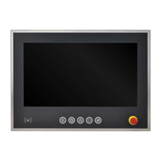
Hygienic design
Brand:
B&R
| Category:
Touch Panel
| Size: 4.05 MB
Table of Contents
Table of Contents
2
1 Introduction
7
Manual History
7
Information about this Document
8
Organization of Notices
8
Guidelines
8
2 General Safety Guidelines
9
Intended Use
9
Protection against Electrostatic Discharge
9
Packaging
9
Regulations for Proper ESD Handling
9
Regulations and Measures
9
Transport and Storage
10
Installation
10
Operation
10
Protection against Contact with Electrical Parts
10
Ambient Conditions - Dust, Moisture, Aggressive Gases
10
Programs, Viruses and Malicious Programs
11
Cybersecurity Disclaimer for Products
11
3 System Overview
12
Information about this User's Manual
12
Description of Individual Modules
12
Panels
12
Link Modules
13
System Units
13
Design/Configuration
14
Configuration
14
Overview
15
4 Technical Data
16
Complete System
16
Connection Options
16
SDL Operation
16
DVI Operation
18
SDL3 Operation
20
SDL4 Operation
21
Electrical Properties
22
Power Calculation
22
Environmental Properties
26
Temperature Specifications
26
Minimum Ambient Temperature During Operation
28
Temperature During Storage and Transport
29
Temperature Sensor Positions
30
Relative Humidity
31
Vibration and Shock
32
Encoder Interface Link Module
33
SDL/DVI Receiver (5DLSDL.1001-00)
33
SDL3 Receiver (5DLSD3.1001-00)
39
SDL4 Receiver (5DLSD4.1001-00)
42
System Unit Device Interfaces
45
System Unit PPC2100 (5Ppc2100.Byxx-000)
45
System Unit PPC2200 (5Ppc2200.Alxx-000)
51
Features
57
AP92D - Features
57
AP93D - Features
59
AP99D - Features
61
Individual Components
68
Panels
68
5Ap92D.1505-I00
68
5Ap92D.1906-I00
70
5Ap93D.185B-B62
72
5Ap93D.240C-B62
74
5Ap99D.156B-B62
76
5Ap99D.185B-B62
79
5Ap99D.215C-B62
82
Link Modules
84
5Dlsdl.1001-00
84
5Dlsd3.1001-00
86
5Dlsd4.1001-00
88
System Units
90
5Ppc2100.Byxx-000
90
5Ppc2200.Alxx-000
93
Interface Options
96
Battery Compartment
97
5Accbt01.0000-001
97
Cfast Cards
97
5 Installation and Wiring
98
Important Information for Installation/Commissioning
98
Alignment of the Swing Arm Connection for AP93D and AP99D
98
Installing Optional Control Elements
101
Connecting to the Power Grid
102
Installing the DC Power Cable
102
Wiring
102
Connecting the Power Supply to a B&R Device
103
Grounding Concept - Functional Ground
104
Connecting Cables
105
6 Commissioning
106
Basic Information
106
Switching on the Device for the First Time
106
General Information before Switching on the Device
106
Switching on the Automation Panel
106
Touch Screen Calibration
107
Single-Touch (Analog Resistive)
107
Windows 10 Iot Enterprise 2016 LTSB
107
Windows 10 Iot Enterprise 2015 LTSB
107
Windows Embedded 8.1 Industry Pro
107
Windows 7 Professional / Ultimate
107
Windows Embedded Standard 7 Embedded / Premium
107
Windows XP Professional
107
Windows Embedded Standard 2009
107
Multi-Touch (Projected Capacitive - PCT)
108
Windows 10 Iot Enterprise 2016 LTSB
108
Windows 10 Iot Enterprise 2015 LTSB
108
Windows Embedded 8.1 Industry Pro
108
Windows 7 Professional / Ultimate
108
Windows Embedded Standard 7 Premium
108
Display Brightness Control
109
Adjusting in SDL / SDL3 / SDL4 Mode
109
Adjusting in DVI Operation
109
7 Software
110
Upgrade Information
110
Automation Panel Firmware Upgrade
110
Automation Device Interface (ADI)
111
ADI Driver
111
Installation
111
Control Center
111
ADI Development Kit
112
Adi .Net Sdk
113
Key Editor
114
RFID Read/Write Transponder Unit
115
Commissioning
115
Connection
115
Supported Operating Systems
115
Driver Installation
115
Port Settings
115
Terminal Program
115
RFID Command Set
116
Commands
116
General Commands
116
Upgrade Commands
116
Mifare
117
MIFARE Commands
117
Authentication
117
Access Rights and Memory Organization
118
Value Block
118
Access Rights
119
MIFARE Commands - Examples
120
Iso15693
120
ISO 15693 Commands
120
Memory Organization
121
Flag Definitions
122
ISO 15693 Commands - Examples
123
Error Codes
124
Error Messages and Error Numbers
124
8 Standards and Certifications
127
Directives and Declarations
127
CE Marking
127
EMC Directive
127
Low Voltage Directive
127
Certifications
127
UL Certification
128
UL - Additional Information
128
9 Accessories
129
Accessories - Information
129
Cables
129
Terminal Block Power Supply
130
0Tb103.9X
130
Order Data
130
Technical Data
130
Cage Clamp Terminal Block for Wiring Emergency Stop
131
0Tb1104.8100
131
General Information
131
Order Data
131
Technical Data
131
Screw Clamp Terminal Block for Wiring B&R Illuminated Ring Keys
132
0Tb1112.8010
132
General Information
132
Order Data
132
Technical Data
132
USB Flash Drives
133
5Mmusb.XXXX-01
133
General Information
133
Order Data
133
Technical Data
133
Temperature/Humidity Diagram
134
5Mmusb.032G-02
135
General Information
135
Order Data
135
Technical Data
135
Temperature/Humidity Diagram
136
Line Filter
137
5Ac804.Mflt-00
137
General Information
137
Order Data
137
Technical Data
137
Dimensions
138
Drilling Template
138
Connecting to the End Device
138
Replacement Screws
139
5A9000.75, 5A9000.76
139
General Information
139
Order Data
139
Technical Data
139
Replacement Gaskets
140
5A9000.73, 5A9000.74
140
General Information
140
Order Data
140
Technical Data
140
Replacement Gaskets
141
5A9000.D3, 5A9000.D4, 5A9000.D5, 5A9000.D6, 5A9000.D7
141
General Information
141
Order Data
141
Technical Data
141
Replacement Parts
142
Replacement Parts - Order Data
142
5ACCRPC2.0003-000 - Technical Data
142
10 Maintenance
143
Cleaning
143
User Tips for Increasing the Service Life of the Display
144
Backlight
144
Measures to Maintain Backlight Service Life
144
Image Persistence
144
What Causes Image Persistence
144
How Can Image Persistence be Reduced
144
Pixel Errors
144
System Units
144
Repairs/Complaints and Replacement Parts
145
Appendix a
146
Mtcx
146
Abbreviations
146
Viewing Angles
146
Chemical Resistance
147
Autotex Panel Overlay (Polyester)
148
Touch Screen
149
Features
150
A.B.1 RFID Read/Write Transponder Unit
150
A.B.2 Emergency Stop Schlegel FRVKPOOI
150
Touch Screen
151
A.C.1 Touch Screen (Single-Touch)
151
A.C.1.1 Technical Data
151
A.C.1.2 Temperature/Humidity Diagram
151
A.C.2 3M Touch Screen (Multi-Touch Generation 3)
151
A.C.2.1 Technical Data
151
A.C.2.2 Temperature/Humidity Diagram
152
LED "S/E" (LED "Status/Error")
153
Ethernet Mode
153
POWERLINK V2 Mode
153
System Stop Error Codes
155
Powerlink V2
155
12 Environmentally Friendly Disposal
156
Separation of Materials
156
Advertisement
Advertisement
Related Products
B&R Automation Panel 5000
B&R Panel PC 2100
B&R Mobile Panel 7200
B&R Automation Panel 1000
B&R Power Panel 500 Series
B&R Mobile Panel 40
B&R Mobile Panel 50
B&R PP21
B&R Panel PC 2200
B&R PC 1200
B&R Categories
Industrial PC
Touch Panel
Industrial Equipment
Control Panel
Controller
More B&R Manuals
Login
Sign In
OR
Sign in with Facebook
Sign in with Google
Upload manual
Upload from disk
Upload from URL