
Related Manuals for Simrad SX90 - REFERENCE MANUAL REV D


Summary of Contents for Simrad SX90 - REFERENCE MANUAL REV D
- Page 1 Reference manual Simrad SX90 Fish finding sonar www.simrad.com T E C H N O L O G Y F O R S U S T A I N A B L E F I S H E R I E S...
- Page 3 Simrad SX90 Fish finding sonar. For user information in brief, refer to the Simrad SX90 Operator manual. WARNING: The Simrad SX90 sonar must never be powered up when the ship is in dry dock.
- Page 4 Support If you require maintenance on your Simrad product contact your local dealer. You can also contact us using the following address: simrad.support@simrad.com. If you need information about our other products, visit www.simrad.com. On our web site you will also find a list of our dealers and distributors.
-
Page 5: Table Of Contents
Reference manual Table of contents ABOUT THIS MANUAL ............9 SIMRAD SX90 FISH FINDING SONAR......10 Important matters ....................10 Basic information ....................11 Main units....................... 11 Wheelhouse units..................12 Sonar room units..................13 System diagram ......................14 Basic functionality....................14 Omni beam....................15 Multiple frequency operation............... - Page 6 Simrad SX90 How to adjust the gain................. 37 How to adjust the AGC ................38 How to adjust the RCG ................38 How to adjust the TVG ................39 How to adjust the display gain ..............39 Mode procedures ....................39 How to select operational mode ..............
- Page 7 Reference manual Bow up/Dual Vertical .....................63 Bow up/180° Vertical .....................64 True motion ......................65 True motion/Vertical....................66 North up........................67 Dual 1 ........................68 Dual 2 ........................69 270°/Vertical......................70 OPERATING PANEL ............71 ’Main switch’ field ....................72 ’Symbol’ field......................73 ’Mode’ field ......................75 ’Gain’ field ......................75 ’Range’...
- Page 8 Simrad SX90 Warnings menu..................104 Operator Alarms menu ................105 System Alarms menu ................106 Errors menu....................107 PARAMETERS ..............108 About the parameter dialogs.................109 Alphabetical list of parameters................110 Parameter descriptions ..................111 About......................111 AGC ......................112 Audio Volume ...................113 Beam ......................114...
- Page 9 Reference manual PP Filter....................146 Pulse Form ....................147 Range ...................... 149 Range (CatchView)................... 150 RCG ......................151 Recall ...................... 152 Recall Mode ..................... 153 Ruler......................154 Scale......................155 School Data....................156 Scientific Output..................157 Search Sector.................... 158 Search Step ....................159 Sector ......................
- Page 10 Simrad SX90 What is RCG? ..................186 About search sectors ................. 186 About tilt....................187 Noise and reverberation..................187 Cavitation....................188 Reverberation ................... 188 Blocking ....................189 Check the noise yourself! ................189 Layers and deflections ..................190 Temperature and salinity layers..............190 Deflections ....................
-
Page 11: About This Manual
The purpose of this reference manual is to provide the descriptions, procedures and detailed parameter explanations required to allow for safe and efficient use of the Simrad SX90 Fish finding sonar system, as well as a thorough understanding of the system parameters and adjustments. A thorough understanding of system functions and controls is necessary to optimize overall performance. -
Page 12: Simrad Sx90 Fish Finding Sonar
Simrad SX90 SIMRAD SX90 FISH FINDING SONAR Study this chapter to familiarize yourself with the Simrad SX90 Fish finding sonar system. Topics • Important matters on page 10 • Basic information on page 11 • Main units on page 11 •... -
Page 13: Basic Information
Simrad SX90 Fish finding sonar Basic information The Simrad SX90 Fish finding sonar is a long range omnidirectional low frequency sonar. It is designed for medium and large sized fishing vessels, preferably for purse seiners, but it is also well suitable for trawlers. The sonar allows you to choose an operational frequency between 20 to 30 kHz (in 1 kHz steps), and the beam can be electronically tilted from +10 to –60 degrees. -
Page 14: Wheelhouse Units
Processor Unit Microsoft Windows XP® operating system. The software and hardware has been modified by Simrad to suit the SX90 sonar requirements. The purpose of this computer is to allow you to control the sonar. It provides the graphic presentation of... -
Page 15: Sonar Room Units
Simrad SX90 Fish finding sonar Amplifier and loudspeakers An amplifier with one or two loudspeakers may be connected to the Beamformer Unit to provide the audio output. These optional items are not provided with the sonar delivery. Sonar room units... -
Page 16: System Diagram
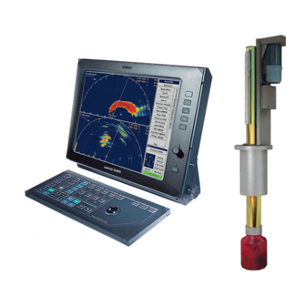
Motor Control Unit Hull Unit Transducer Basic functionality The basic principles of the Simrad SX90 Fish finding sonar are unique because of the 256 separate transmitter and receiver channels with their transducer elements spread around on the cylindrical transducer array. -
Page 17: Omni Beam
Simrad SX90 Fish finding sonar Omni beam When the Omni beam is tilted, the total beam picture can be compared with folding an umbrella, which means that all beams in 360 degrees around the vessel have the same tilt angle. - Page 18 Simrad SX90 Figure 3 60 degrees vertical slice This vertical slice, which is presented by the white audio line in the horizontal picture, can be selected to any bearing by the manual training control. The combination of the Omni mode and the vertical slice will give an optimal visualization of the catch situation.
-
Page 19: Multiple Frequency Operation
This is a very useful function when it is necessary to suppress interference from other sonars. Stabilisation system The Simrad SX90 Fish finding sonar is provided with a stabilisation system. When the beam stabilizer is activated, both horizontal and vertical beams will be stabilized electronically for roll and pitch movements up to ±20 degrees. -
Page 20: Reception
• TVG (Time Variable Gain) FM Correlation filter In addition to the traditional single frequency transmitting method, the Simrad SX90 Fish finding sonar is equipped with an FM correlation mode. In FM mode each transmission pulse contains up to eight... -
Page 21: Transmission
The options described below are preprogrammed into the standard software version, and a code word is required to make the actual option available. Simrad offers a 1 month free test period for certain options. The Scientific Output function is not... -
Page 22: Scientific Output
Simrad SX90 available for such a test period. For a permanent installation of a chosen option, a new code word will be released from Simrad when the option is ordered. Scientific output The Scientific Output is designed for research purposes. When... -
Page 23: Peripheral Equipment
• A (D)GPS may be connected to the SP70 sonar to establish the vessels position and provide cursor and marker latitude and longitude. • Simrad echo sounders (EQ, ES and EK Series) provides a bottom plot on the catch data page. • Simrad PI32, PI44 and PI54 Catch Monitoring systems provide the net depth in digits and bars on the catch data presentation. -
Page 24: Getting Started
Simrad SX90 GETTING STARTED Please find the basic information required to get you started up. Topics • Power on/off procedures on page 22 • How to perform basic operations on page 24 • Visual aids on page 29 • Cosmetics on page 30 •... - Page 25 Getting started • When the bottom position has been reached, the lamp will be lit continuously, the audible signal stops, and the top button in the parameter dialog shows Status Transducer:Down • By default the transmit power is disabled when the sonar is powered up.
-
Page 26: How To Perform Basic Operations
Simrad SX90 Please note: • If the sonar is switched off uncontrolled with the transducer in its lowered position, the transducer must be raised manually by means of the hoist/lower switch in the Motor Control Unit, or with the hand crank provided. -
Page 27: Temporary Menu
Getting started Temporary menu On the Operating Panel, press the button to remove Menu the menu. On the display, observe that the menu disappears. Use the trackball, and move the cursor over to the left side of the display. Observe that the menu reappears on the left hand side, and that the remaining echo presentation area is not re-scaled. -
Page 28: The Menu Structure
Simrad SX90 The menu structure The menu on the right hand side of the sonar display contains several different buttons, tabs and parameter dialogs. The following elements are in use on the menu: : This field simply states the Sonar type name of the sonar. -
Page 29: Control The Cursor
Getting started Control the cursor Operate the trackball (A) on the Operating Panel. Observe that the cursor moves on the sonar display, and that it changes its form depending on its location. Observe the location of the button (B). Select Press this button to make a selection. - Page 30 Default setting Setup dedicated parameter dialog is used. In the Simrad SX90 sonar, all parameters are stored. This function will cause the sonar to remember all the selected parameter settings, even when the sonar is switched off. 307670/D...
-
Page 31: Visual Aids
Getting started Visual aids The sonar display contains not only the sonar picture and the menu system, but also other information that is useful for efficient operation. Common information on the display In nearly all display modes, the following information is provided. -
Page 32: Cosmetics
Simrad SX90 Cosmetics The choices in the menu allows you to enable or Cosmetics disable a range of visual aids in the sonar picture. Click the tab to open the menu. Display Display Click the button to open the menu. - Page 33 Getting started Figure 11 Variable Range Marker (D), Compass Card (E) and Vertical Ring (F) (D) consists of an adjustable Variable Range Marker (VRM) range ring with range read-out. It can be used for any type of distance marking relative to the vessel. To adjust the marker, locate the cursor on the marker ring, press the on the Select...
-
Page 34: On-Line Help
On-line help The Simrad SX90 sonar is equipped with a comprehensive on-line help system. Help is provided in two levels: On-line and Free. It is available from all the parameter dialogs and menus by clicking the button. - Page 35 Getting started the information is accessed using the menu on the left hand side and interactive links throughout the document. Click in the Free bottom left corner to return to the small on-line dialog, or Close to exit the interactive manual. Note If you click button to close the large interactive manual...
-
Page 36: Operational Procedures
Simrad SX90 OPERATIONAL PROCEDURES This chapter presents how to perform the most common procedures on the SX90 sonar. Note that the power on/off procedures have been previously explained. Topics • Power on/off procedures on page 34 • Menu procedures on page 36 •... - Page 37 Operational procedures Press the button on the control panel to lower the Down transducer. • The green lamp next to the button will flash, and an audible signal indicates that the transducer moves downwards. • When the bottom position has been reached, the lamp will be lit continuously, the audible signal stops, and the top button in the parameter dialog shows...
-
Page 38: Menu Procedures
Simrad SX90 Press the button on the Operating Panel, and keep it Power depressed for approximately two seconds. • The sonar is switched off. Note that you must not use the on/off switch on the Processor and Beamformer Units, only this button on the Operating Panel. -
Page 39: How To Simplify The Menu
Operational procedures How to simplify the menu You can easily reduce the number of buttons on the sonar menus. This can be useful if you never use them. Procedure Click the tab to open the menu. Display Display Click the button. -
Page 40: How To Adjust The Agc
Simrad SX90 Click the left or right side of the button to decrease or Gain increase the gain, or the middle of the button to open the parameter dialog. For more information about this parameter, see About Gain on page 185. -
Page 41: How To Adjust The Tvg
Operational procedures Click the left or right side of the button to decrease or increase the setting, or the middle of the button to open the parameter dialog. For more information about this parameter, see What is RCG? on page 186. How to adjust the TVG (Time Varied Gain) controls the gain in the signal amplifier. -
Page 42: How To Select Operational Mode
Simrad SX90 Related topics • Display modes on page 58 How to select operational mode Your SX90 sonar is equipped with several operational modes. Observe these procedures to choose the mode best fit for your current operations. Procedure Locate the... -
Page 43: Markers And Symbols Procedures
Operational procedures Procedure Click the tab to open the menu. Setup Setup Click the button to open the menu. Sort Modes Sort Modes • The menu lists all the available modes in their Sort Modes current order. Click one of the operational modes. •... -
Page 44: How To Add An Own Ship Symbol
Simrad SX90 • The target marker data is displayed in white figures for 15 minutes in the lower right hand corner of the horizontal presentation. • This function is also an effective method for determining the distance between two selected points on the screen. - Page 45 This is a useful aid in providing an overview of the trawl operation. Trawl data can be set manually using the menu or automatically by interfacing a Simrad FS trawl sonar or Simrad ITI trawl monitoring system with the sonar.
-
Page 46: How To Investigate Marker And Symbol Information
Simrad SX90 How to investigate marker and symbol information Observe the following procedure to read the information related to each marker or symbol. Procedure Click the tab to open the menu. Objects Observe that all the current objects (markers and symbols) are listed. -
Page 47: Storage Procedures
Operational procedures Alternative method Place the cursor on the object. Press the button on the Operating Panel (or the right Object mouse button) Click on the menu. Delete Storage procedures This section explains how to store and recall sonar images on the SX90. -
Page 48: How To Recall Sonar Images
Simrad SX90 Record a single image Either: Click the button, or Store Press the button on the Operating Panel Record Observe that the message field below the menu displays the image file name on a green background. Record multiple images... -
Page 49: How To Keep Sonar Images
Operational procedures To recall several images Click the button, and select how long time you Recall mode wish to see each image. To select a number of images files, click the top file, then hold the button on the Operating Panel depressed Select while you move the cursor down to select the other files in the field. -
Page 50: How To Rename Sonar Images
Simrad SX90 How to rename sonar images Observe the following procedure to print selected sonar images. Click the tab to open the menu. Setup Click the button to open the menu. Store/Recall Store/Recall Observe the list of images in the menu. -
Page 51: How To Burn Sonar Images On A Cd
Operational procedures Click one of the images to select it. Click the button below the files to print the selected Print image. The image will be sent to the default printer connected to the Processor Unit. You are not allowed to control the output size and format. -
Page 52: Automatic Search And Tracking Procedures
Simrad SX90 Note This procedure assumes that you have basic knowledge of file management in Windows. Insert a USB memory stick into the Processor Unit. Observe that the operating system’s auto-start function opens a dialog requesting guidance. Select , and click... -
Page 53: How To Start The Vertical Search Program
Operational procedures Hold the button depressed while you also press Auto search one of the two buttons in the field. “arrow” Train Observe that the opening angle of the search sector is adjusted accordingly. Release the button, press and hold one of the Auto search buttons. -
Page 54: How To Enable Target Track
Simrad SX90 Press the button in the field on the Position track Train Operating Panel. A geographically fixed circle will appear on the display, and its position will automatically be tracked by the system with respect to the bearing and tilt angle. The track parameters can be investigated by accessing the menu. -
Page 55: How To Add A Target Tracking Line
Operational procedures How to add a target tracking line Observe this procedure to add a tracking line to a tracked target to indicate its movement history. Procedure Choose an operational mode with a horizontal presentation. Place the cursor in the horizontal presentation. Press the button in the field on the Operating... -
Page 56: How To Load A User Setting
Simrad SX90 How to load a user setting Observe the following procedure to load a predefined user setting. Procedure Click the tab to open the menu. Setup Click the button to open the parameter dialog. User setting Click the desired user setting to select it. -
Page 57: How To Delete A User Setting
Operational procedures How to delete a user setting Observe the following procedure to delete a predefined user setting. Procedure Click the tab to open the menu. Setup Click the button to open the parameter dialog. User setting Click the desired user setting to select it. Click the button. -
Page 58: Installation Of Options
Optional functionality may be added to the SX90 sonar. All options are pre-programmed into the standard sonar version, and that Simrad offer a 1 month free test period for certain options. When ordering a permanent option installation, a code word will be released from Simrad. For a free test, or permanent option installation, use the following procedures. - Page 59 Operational procedures Send the number to your dealer. Makes sure that you HWID write down the character string correctly! Use the sonar without the option until your dealer approaches you with a code word. Open the parameter dialog, and click the Install Options number.
-
Page 60: Display Modes
Simrad SX90 DISPLAY MODES This chapter describes the Simrad SX90 display modes. The various modes represent the graphical presentation of sonar data. Several display modes are available to present the best possible presentations as well as flexible choices for a large range of user applications. - Page 61 Display modes Alternative method Locate the button on the top of each menu. Mode Click the button to choose operational mode. Mode Click the left or right side of the button to choose Mode mode, or the middle of the button to open the parameter dialog.
-
Page 62: Bow Up
Simrad SX90 Bow up When Bow up mode is selected, the vessel symbol is stationary on the screen with the bow pointing upwards. The echo presentation covers 360 degrees around the vessel, and all echoes are updated for every ping. The distance from the vessel symbol to the outer echo ring is equal to the selected range. -
Page 63: Bow Up/Audio
Display modes Bow up/Audio When Bow up/Audio mode is selected, the upper half of the screen shows a 180 degrees bow-up presentation, while the lower part is used for a recording of the audio channel. The audio channel is shown with a continuous white line in the horizontal picture, and it can be trained in any direction. -
Page 64: Bow Up/Vertical
Simrad SX90 Bow up/Vertical When Bow up/Vertical mode is selected, the picture is divided into three sections; where the left side is a bow-up presentation similar to the Bow up presentation previously described. The upper part on the right hand side is a Catch data presentation, while the lower part is a Vertical slice presentation. -
Page 65: Bow Up/Dual Vertical
Display modes Bow up/Dual Vertical When Bow up/Dual vertical mode is selected, the upper part of the screen shows a curtailed bow-up presentation, while the lower part shows two vertical slice presentations. The bearing of the left vertical presentation is indicated by the white audio line in the horizontal presentation, while the bearing of the right vertical presentation is indicated by the yellow-dashed line. -
Page 66: Bow Up/180° Vertical
Simrad SX90 Bow up/180° Vertical When the Bow up/180° Vertical mode is selected, the upper part of the screen shows a curtailed Bow up presentation, while the lower part shows a 180 degrees Vertical slice presentation. This mode is mainly intended for trawlers, where the vertical view acts as a multibeam echo sounder. -
Page 67: True Motion
Display modes True motion When True motion mode is selected, the picture is locked to a geographical position, where the vessel moves around the screen according to its present course and speed. All echoes are always presented in their correct position relative to the vessel, and their movements on the screen will be a true representation of the movements of the targets through the water. -
Page 68: True Motion/Vertical
Simrad SX90 True motion/Vertical When True motion/Vertical mode is selected, the picture is divided into three sections; where the left side is a True motion presentation similar to the true motion presentation previously described. The upper part on the right hand side is a Catch data presentation, while the lower part is a Vertical slice presentation. -
Page 69: North Up
Display modes North up When North up mode is selected, true north is always up on the screen. The vessel symbol is stationary with the bow pointing in the vessel’s course direction. The movement of the echoes across the screen are controlled by a combination of the vessel’s course and speed and the target’s own movements. -
Page 70: Dual 1
Simrad SX90 Dual 1 The Dual 1 mode is a kind of “two sonars in one” operation, where each presentation is updated for every second transmission. All settings can be set individually for each of the two presentations. This makes the dual mode especially useful for optimizing settings by directly comparing the two presentations. -
Page 71: Dual 2
Display modes Dual 2 The Dual 2 mode is very similar to the Dual 1 mode previously described, but the “two sonars” are presented next to each other. All settings can still be set individually for each of the two presentations. -
Page 72: 270°/Vertical
Simrad SX90 270°/Vertical The 270°/Vertical mode is specially designed for purse seining. The vertical half slice is displayed in the lower left corner for normal setting with the net on the starboard side. If the net is set on the port side, the 60 degrees vertical slice will be displayed in the lower right hand corner. -
Page 73: Operating Panel
Operating panel OPERATING PANEL This chapter describes the Simrad SX90 Operating Panel. The frequently used functions are directly accessible by the designated control buttons on the Operating Panel, and may enter operational commands directly. The buttons are grouped in fields according to their purpose. Most sonar functions are also... -
Page 74: Main Switch' Field
Simrad SX90 ’Main switch’ field buttons controls the power on/off sequence and Main switch the hoisting and lowering of the transducer array. It also indicates the transducer array’s current position. Power This is the sonar’s “on/off” switch. • Pushing for approximately two seconds powers up the Power sonar. -
Page 75: Symbol' Field
Operating panel ’Symbol’ field buttons provide on-screen graphic references for Symbol targets, own ship and fishing gear. (A) Target marker To mark a target, move the cursor over it and press the button. A triangular symbol with a corresponding number will appear on the screen over the target. - Page 76 This is a useful aid in providing an overview of the trawl operation. Trawl data can be set manually using the menu or automatically by interfacing a Simrad FS trawl sonar or Simrad ITI trawl monitoring system with the sonar.
-
Page 77: Mode' Field
Operating panel ’Mode’ field The four buttons can be used to select either the four Mode favourite display modes or user settings. The set up the buttons to choose modes or settings, select in the Mode Buttons Display menu. Depending on the selection you make in the Mode Buttons parameter dialog, you have two options: you can select a mode or a user setting. -
Page 78: Range' Field
Simrad SX90 ’Range’ field Range controls are specified as either horizontal or vertical. Horizontal range The two upper buttons control the horizontal range. The Range range selected is displayed in the menu, and on top of Horizontal the tilt indicator in the upper left corner of the display. -
Page 79: Train' Field
Operating panel the cursor may be used to activate the menu field by moving it to the left or right extremes of the screen. If you move the cursor outside the menu field it will hide the menu. Select button is used to execute a selection. This corresponds Select to the left button on a standard computer mouse. - Page 80 Simrad SX90 Manual In the Manual mode the (arrow) buttons Train left Train right are used to direct the audio line to the desired bearing. Auto search In the Auto search mode the sonar will automatically search within previously defined sector limits with the selected audio line designating the centre of the search.
-
Page 81: Tilt' Field
Operating panel • When the Auto tilt function is activated in the Target track mode, the tilt search centre is automatically adjusted with regard to the distance to the tracked position. Note Manual training overrides the Target Tracking function. ’Tilt’ field buttons allows you to control the vertical angle of the Tilt transducer beam, and provide a program for an automatic tilt... -
Page 82: Various' Field
Simrad SX90 • Auto search training mode: The transducer automatically changes the tilt angle after each complete search is performed. • Position and Target Tracking modes: The tilt angle’s search centre will automatically be adjusted with regard to the distance to the position being tracked. The transducer will tilt automatically in steps after each transmission. - Page 83 Operating panel Zoom The Zoom function magnifies an area of the display by positioning the cursor in its centre and pressing the button. The Zoom Zoom button works as a toggle switch for on/off of the zoom function. Off centre The Off centre function moves the symbol to the Own vessel...
-
Page 84: Menu Descriptions
• Alphabetical list of parameters on page 110 About the menus The Simrad SX90 Fish finding sonar comprises a large number of different menus on several levels. Menus are selected by pressing their respective tabs on the right hand side, and the appearance of menus and tabs depends on the chosen operational mode and the current settings. -
Page 85: Active Menus
Menu descriptions Active menus The active menus are those relevant for the different operational modes. The menus are shown with vertical selector tabs on the right hand side, and each menu can easily be selected using the trackball and the button on the Operating Panel. - Page 86 Simrad SX90 • : Use this function to select the form of the Pulse Form transmitted pulse. This could either be FM (Frequency modulation) with different pulse lengths and number of frequencies, or CW with different pulse lengths. (► Pulse Form on page 147) •...
-
Page 87: Vertical Menu
Menu descriptions Vertical menu Menu description menu is only shown in modes Vertical with a vertical slice function. All relevant settings, except the , can be TX Power selected separately for the vertical modes independent of the horizontal settings. When any vertical setting is selected and defined in one mode, the setting will be applied to all vertical modes. -
Page 88: Vertical 180 Menu
Simrad SX90 • : Time Varied Gain. This function will automatically adjust the gain in the sonar to compensate for geometric spread and absorption. Note that the TVG will only work within the first 1000 meters. (► TVG on page 176) •... - Page 89 Menu descriptions • : Use this setting to tip the vertical slice to avoid the blind zone. (► Tip on page 169) • : Use this function to adjust the bearing. (► Bearing Bearing (Vertical) on page 117) • : This setting controls the amplification of the received Gain echoes in the vertical presentation.
-
Page 90: Display Menu
Simrad SX90 Display menu Menu description menu is shown in all display Display modes, and provides access to parameters controlling the visual presentation of the sonar views. Some of the choices on the menu are simple on/off buttons. Menu buttons •... -
Page 91: Setup Menu
Menu descriptions • : Use this button to choose how the buttons Mode buttons Mode on the Operating Panel shall work. You can either choose between the four most frequent modes, or the four most frequent user settings. (► Mode Buttons on page 141) •... - Page 92 Simrad SX90 • : Click this button to access the sonar’s test software. Test These utilities are only provided for certified service technicians, and they are not documented. (► System Test menu on page 95) • : This button is used to select the type of fishing gear you...
-
Page 93: Objects Menu
• : This function makes it possible External sync(hronisation) to eliminate interference from other Simrad sonars on board your vessel. If the sonars are connected together, you can use these settings to synchronise their transmissions. (► External Synchronisation on page 129) •... -
Page 94: Temporary Menus
Simrad SX90 Using the Objects menu Observe the following guidelines for use: • To delete an object, select the relevant marker in the list, and click the Delete button in the lower part of the menu. • Click the button to delete all Delete All objects. -
Page 95: Cosmetics Menu
Menu descriptions Cosmetics menu Menu description menu is activated by Cosmetics pressing the button in the Cosmetics menu. The menu provides access Display to various parameters controlling the appearance of the sonar picture. All the functions - except Track History - are on/off buttons. -
Page 96: Store/Recall Menu
Simrad SX90 • : Displays an arrow drawn from the Compass Wind Marker Card pointing towards the centre of the display, shows the current wind direction if a suitable sensor has been connected to the sensor. • : Displays the selected range of the vertical slice Vertical Ring as a full circle in the horizontal presentation. -
Page 97: System Test Menu
Menu descriptions • button: Click this button: to transfer a selected Transfer preliminary file to the permanent file storage. • : This text field displays the list of permanent Permanent files files. These will not be deleted when you switch off the sonar. •... - Page 98 Simrad SX90 • : This button provides a read-out of the current noise Echo level in the waters surrounding the vessel. This noise is caused by air bubbles, water flow and mechanical disturbances from hull and engine. In order to obtain the best possible sonar result, the noise level read-out should be as close to 0.0 dB...
-
Page 99: Sort Modes Menu
Menu descriptions Sort Modes menu Menu description menu is activated by the Sort Modes button in the menu. Sort Modes Setup (► Setup menu on page 89) This menu is used to select the display modes to be activated by the four Mode buttons on the Operating Panel. -
Page 100: Catch View Pop-Up Menu
Simrad SX90 Parameters • : When this function is selected, the Set New Display Centre new display centre is moved to the cursor’s position where menu was activated. View • : When this function is selected, the own ship Ship To Centre symbol is moved to the centre of the view. -
Page 101: Object Pop-Up Menu
Menu descriptions Parameters • : When this function is selected, all echoes Erase Echoes displayed on the sonar view will be deleted. • : When this function is selected, window areas Make Same Size tiled vertically will acquire the same width. •... -
Page 102: View Menus
Simrad SX90 Basic parameters These menu choices provide the same functions as their respective buttons on the Operating Panel. • Target Track • Position Track • Set Marker • New Own Ship Marker • Circle Marker • Gear Symbol For more information about the... -
Page 103: Geoview Menu
Menu descriptions GeoView menu Menu description menu is activated by GeoView pressing the button on the Operating View Panel or the middle mouse button in any horizontal view, and then selecting View in the pop-up. Menu View menu provides control of GeoView selected parameters related to the current data displayed in the horizontal view;... -
Page 104: Verticalview Menu
Simrad SX90 VerticalView menu Menu description menu is activated by VerticalView pressing the button on the Operating View Panel (or the middle mouse button) while positioning the cursor in any of the vertical views, and then selecting View in the pop-up. -
Page 105: Catchview Menu
Menu descriptions CatchView menu Menu description menu is activated by CatchView pressing the button on the Operating View Panel (or the middle mouse button) while the cursor is located in the Catch view, and then selecting in the View menu View pop-up. -
Page 106: Warnings Menu
Simrad SX90 one or more unread messages exists, the Warning Operational buttons are yellow, while the Alarm System Alarm Error buttons are red. Figure 27 The Message Bar buttons Related topics • Message Bar on page 138 Warnings menu Menu description... -
Page 107: Operator Alarms Menu
Menu descriptions Operator Alarms menu Menu description menu is activated Operator Alarms from the button in the Op Alarms Message . (► Message Bar on page 138) The menu displays the operator alarms issued by the sonar. Each alarm is identified with time of issue and a heading. -
Page 108: System Alarms Menu
Simrad SX90 System Alarms menu Menu description menu is activated System Alarms from the button in the Sys Alarms Message . The menu displays the system alarms issued by the sonar. Each alarm is identified with time of issue and a heading. -
Page 109: Errors Menu
Menu descriptions Errors menu Menu description menu is activated from the Errors button in the . The Errors Message Bar menu displays the error messages issued by the sonar. Each alarm is identified with time of issue and a heading. Additional information is found in the small text field below the message list. -
Page 110: Parameters
Simrad SX90 PARAMETERS This section provides a detailed description of the parameter dialogs used by the Simrad SX90 Fish finding sonar system. The chapter Menu structure gives a description of the menu system configuration with references to more detailed descriptions of all the menu. Any selections you do in the menus will bring up the parameters available for the chosen setting. -
Page 111: About The Parameter Dialogs
Parameters About the parameter dialogs When a parameter is selected, the available choices are shown in the dialog below the menu. The setting is then made using the available buttons or lists. Several levels are frequently used to select the parameters. Note that: In many cases you will not need to open the parameter dialog, as you can control the settings directly on the menu button. -
Page 112: Alphabetical List Of Parameters
Simrad SX90 Alphabetical list of parameters About on page 111 Menu on page 137 Target Track on page 167 AGC on page 112 Message Bar on page 138 Tilt on page 168 Middle Pos on page 139 Audio Volume on page 113... -
Page 113: Parameter Descriptions
Parameters Parameter descriptions About parameter dialog is accessed from the About System test menu. Dialog description dialog is only used to provide information about the About current software version. In addition, the button opens Versions a small text document with detailed version information. This information is not intended for operational use. -
Page 114: Agc
Simrad SX90 parameter dialog opens when you click the button in the menus. Horizontal Vertical Vertical 180 Dialog description function adjusts the gain AGC (Automatic Gain Control) in the sonar’s preamplifier circuitry. This gain depends on the strength of the incoming echo signal. The result is a filter effect, reducing noise and reverberation. -
Page 115: Audio Volume
Parameters Audio Volume This parameter dialog opens when you click the Audio Volume button in the menus. Horizontal Vertical The audio volume in the loudspeaker can be selected in 10 steps. The audio channel, from which the audible information is retrieved, is shown with a continuous white line. -
Page 116: Beam
Simrad SX90 Beam This parameter dialog opens when you click the button Beam in the menu. Horizontal Dialog description This function enables you to select the vertical beam width in the horizontal presentation. The beam selection can be made manually, or controlled automatically by the selected range. -
Page 117: Bearing (Display)
Parameters Bearing (Display) parameter dialog opens when you click the Bearing (Display) button in the menu. Bearing Display Dialog description This is simply a selector switch. Click on the button to select True north or Relative Ship. Certain bearing data will change their values accordingly. -
Page 118: Bearing (Horizontal)
Simrad SX90 Bearing (Horizontal) parameter dialog opens when you click the Bearing Bearing button in the menu. Horizontal Dialog description The horizontal bearing of the audio channel is normally controlled from the Operating Panel. The selected bearing is shown with a continuous white line pointing out from the transducer position. -
Page 119: Bearing (Vertical)
Parameters Bearing (Vertical) parameter dialog opens when you click the Bearing (Vertical) button in the menu. Bearing Vertical Vertical 180 This dialog allows you to train the audio channel bearing manually. The bearing of the audio channel is normally controlled with the buttons on the Operating Panel. -
Page 120: Colour Threshold
Simrad SX90 Colour Threshold parameter dialog opens when you click the Colour Threshold button in the menu. Colour Threshold Display This function is used to reduce the number of echo colours on the display. The strength of the echoes is indicated with a scale of 16 or 64 colours. -
Page 121: Colours
Parameters Colours parameter dialog opens when you click the Colours Colours button in the menu. Display The colour strength of the echo presentation can be selected with three different colour scales. Under normal conditions, normal colours will give the best dynamic in the echo presentation, while strong colours are preferred for weaker echoes. -
Page 122: Data Source
Simrad SX90 Data Source parameter dialog opens when you click the Data Source Data button in the menu. Source VerticalView menu is are opened by pressing the button VerticalView View on the Operating Panel (or the middle mouse button) while... -
Page 123: Date And Time Properties
Parameters Date and time properties dialog box is accessed by pressing Date and time properties buttons in the default parameter dialog Time Date Status at the bottom of the menus. The time and date information is battery powered and stored in the memory when the sonar is switched off. -
Page 124: Dead Reckoning
Simrad SX90 Dead Reckoning parameter dialog opens when you click the Dead Reckoning button in the menu. Dead Reckoning Setup function is used to improve the position of Dead Reckoning the historical track line from the vessel, relative to the actual position of the drifting fishing gear. -
Page 125: Default Setting
This function makes it possible to delete all the parameters currently saved in the sonar’s memory, and reinstall those defined by Simrad instead; the factory default settings. These default settings are identified with an asterisk in the different parameter dialogs and menus, and will perform well under normal conditions. -
Page 126: Direction Indicator
Simrad SX90 Direction Indicator parameter dialog opens when you click Direction Indicator button in the menu. Note Direction Indicator VerticalView that must be set to Indicator in order to access this Data Source parameter. menu is activated by pressing the... -
Page 127: Display Gain
Parameters Display Gain parameter dialog opens when you click the Display Gain button in the menu. Display Gain Display This command increases or decreases the presentation of the echo colours on the display. In order to adjust the receiver gain, refer to the individual parameters accessed in the Gain... -
Page 128: Edit Gear (Purse)
Simrad SX90 Edit Gear (Purse) parameter dialog opens when you click the button Gear Gear on the menu. Each of the available options in the Setup Gear dialog can be edited using the button. When a purse has Edit been selected, this parameter dialog is provided. -
Page 129: Edit Gear (Trawl)
Height setting is made automatically if you click the button, Auto provided that a Simrad trawl system is connected to the sonar. If you click , you can define the height in steps of 1 meter. Manual : Click to define the width of the trawl opening. The setting... -
Page 130: Edit School
Simrad SX90 Edit School parameter dialog opens when you click the Edit School button on the menu. In the dialog, select School Setup School species and click . The top button displays the fish species Edit selected in the dialog. -
Page 131: External Synchronisation
External Sync Setup This function makes it possible to eliminate interference from other Simrad sonars on board the vessel. If the sonars are connected together, you can use these settings to synchronise their transmissions. Options : Click to select one of the three synchronization Sync mode modes below. -
Page 132: Fish Alarm
Simrad SX90 Fish Alarm parameter dialog opens when you click the Fish Alarm Fish button on the menu. Alarm Setup This is an on/off switch used to activate or deactivate the fish alarm function. Options : Click to select the inner radius of the circular alarm Start range sector. -
Page 133: Frequency
However, the sound absorption in salt water decreases with the frequency, thus giving lower frequencies a longer range. If only the standard frequency is installed, Simrad offers a one-month free test period for the multiple frequencies. Note This parameter dialog will only be available if the triple or multiple frequency option has been installed on the sonar. -
Page 134: Gain
Simrad SX90 Gain parameter dialog opens when you click the button Gain Gain in the menus. Horizontal Vertical Vertical 180 The sonar gain is normally selected on the Operating Panel. It has 51 values, these are numbered from 0 to 50. The receiver gain is changed 1 dB per step. -
Page 135: Gear
Parameters Gear parameter dialog opens when you click the button Gear Gear in the menu. Setup This dialog is used to select the type of fishing gear you use, and to get the right size and position of the gear on the sonar display. -
Page 136: Heading
Simrad SX90 Heading parameter dialog opens when you click the Heading (Heading) button in the parameter dialog at the bottom Status of the menus. The read-out of the current heading is a repetition of the connected course gyro input. Manual heading input may be used if signals from the external heading sensors are missing. -
Page 137: Inspect Object
Parameters Inspect Object parameter dialog is either accessed when you Inspect Object select a target marker in the menu, or when you place Objects the cursor on the marker and pushes the button on the Select Operating Panel. This parameter dialog displays the current parameters for the chosen object. -
Page 138: Language
Simrad SX90 Language parameter dialog opens when you click the Language button on the menu. Language Display This parameter dialog is used to select the language on the menus. Note The on-line help may not be available in the language you choose to use. -
Page 139: Menu
Parameters Menu parameter dialog opens when you click the Menu Menu button in the menu. Display This parameter dialog allows you to select different levels of complexity in the menu system. Options : Click to see only the most important buttons in the menus. Short This setting is recommended for simplified use. -
Page 140: Message Bar
Simrad SX90 Message Bar parameter dialog opens when you click the Message Bar button in the menu. The Message Bar System Test System Test menu is in turn opened by clicking the button on the Test Setup menu. (► System Test menu on page 95) (► Setup menu on... -
Page 141: Middle Pos
Parameters Middle Pos parameter dialog opens when you click the Middle Pos button in the parameter dialog. Middle Pos Transducer Provided that the hull unit installed on your vessel supports the function, this parameter dialog allows you to define a “middle” vertical position for the transducer array. -
Page 142: Mode
Simrad SX90 Mode parameter dialog opens when you click the Mode Mode button on the top of all menus. This parameter dialog is used to select display mode. It will automatically provide a selection between the modes currently available on the sonar. -
Page 143: Mode Buttons
Parameters Mode Buttons button is located on the menu. Mode Buttons Display This is simply a selector switch. Click on the button to select Mode or User, and by this defining the operational function of the four buttons on the Operating Panel. Mode Options : The four... -
Page 144: Movements
Simrad SX90 Movements parameter dialog opens when you click the Movements button on the menu. Movements Setup This function makes it possible to estimate the position of a tracked school at a given time (from one to ten minutes). Estimated school position is presented by a violet dot. If you select 0, the movement estimation is switched off. -
Page 145: Noise Filter
Parameters Noise Filter parameter dialog opens when you click the Noise Filter Noise button on the menu. Filter Horizontal This parameter dialog allows you to control the built-in filter designed to remove unwanted acoustic noise from the sonar picture. It will reduce the interference from other acoustic systems (sonars and echo sounders) on your own vessel and from other vessels in the vicinity. -
Page 146: Palette
Simrad SX90 Palette parameter dialog opens when you click the Palette Palette button on the menu. Display This parameter dialog allows you to select the background colours and day/night brightness of the display to suit you personal preferences. The choice you make here does not have any effect on the sonar performance. -
Page 147: Panel Backlight
Parameters Panel Backlight parameter dialog opens when you click the Panel Backlight button on the menu. Panel Backlight Display This parameter dialog controls the illumination on the keyboard on the Operating Panel in 8 steps (0 – 7). Note that the backlight can only be manually operated. -
Page 148: Pp Filter
Simrad SX90 PP Filter parameter dialog opens when you click the PP Filter button on the menus. Filter Horizontal Vertical Vertical 180 This filter reduces unwanted noise and echoes from the screen. The filter has three different strengths. As the ping-to-ping filter... -
Page 149: Pulse Form
Parameters Pulse Form parameter dialog opens when you click the Pulse Form Pulse button on the menus. Form Horizontal Vertical Dialog description This parameter dialog is used to select the shape of the transmitter pulses. These can either be CW (Continuous Wave) with different pulse lengths, or FM (Frequency Modulation) with different pulse lengths and a continuous frequency sweep. - Page 150 Simrad SX90 Table 1 CW and FM pulse lengths for different ranges (cont’d.) Range Auto Short Normal Long 8000 (Range in meters, pulse lengths in milliseconds) About CW (Continuous Wave) The frequency of the transmitter pulse is here constant, equal to the selected operational frequency.
-
Page 151: Range
Parameters Range parameter dialog opens when you click the Range Range button in the menus. Horizontal Vertical Vertical 180 Dialog description Horizontal and vertical ranges are normally selected using the buttons on the Operating Panel. You can also control these settings directly using this parameter dialog. -
Page 152: Range (Catchview)
Simrad SX90 Range (CatchView) parameter dialog opens when you click Range (CatchView) button in the menu. The menu Range CatchView CatchView is in turn activated by pressing the button on the Operating View Panel (or the middle mouse button), while the cursor is located... -
Page 153: Rcg
Parameters (Reverberation Controlled Gain) parameter dialog opens when you click the button in the Horizontal Vertical menus. Vertical 180 Dialog description Reverberation Controlled Gain (RCG) regulates the receiver gain individually for each of the 64 receiving beams. If you select weak or medium filter strength, signals with small variations, like propeller noise, surface and bottom reverberations will be removed, while signals with fast variations, like target echoes... -
Page 154: Recall
Simrad SX90 Recall button is located on the menu, which in Recall Store/Recall turn is opened from the menu. Setup button is used to retrieve the previously stored display Recall information. You can select which storage image you wish to see by selecting it from the list of temporary or permanent files, or start a playback sequence. -
Page 155: Recall Mode
Parameters Recall Mode parameter dialog opens when you click the Recall Mode button in the menu. The Recall Mode Store/Recall Store/Recall menu is in turn opened by pressing the button on Store/Recall menu. Setup This parameter dialog is used to select the replay function of the button in the menu. -
Page 156: Ruler
Simrad SX90 Ruler To create a ruler, open the pop-up menu by pressing the Object button on the Operating Panel (or the right mouse button), Object and select in the pop-up menu. New ruler Object parameter dialog opens when you position the cursor... -
Page 157: Scale
Parameters Scale parameter dialog opens when you click the button Scale Scale in the menu. GeoView menu is activated by pressing the button on the GeoView View Operating Panel (or the middle mouse button) in any horizontal view, and then selecting in the pop-up menu. -
Page 158: School Data
Simrad SX90 School Data parameter dialog opens when you click the School Data button in the menu. School Setup This parameter dialog is used to obtain information of the volume estimation of a school in the automatic target tracking program. Four types of known fish species plus “own school”... -
Page 159: Scientific Output
Simrad ITI trawl system or the Simrad PI Series catch monitoring system. • : Click to enable or disable export of own ship Ownship Data data. -
Page 160: Search Sector
Simrad SX90 Search Sector parameter dialog opens when you click the Search Sector button in the parameter dialog. The Search Sector Bearing Bearing parameter dialog opens when you click the button in the Bearing menu. Horizontal This parameter dialog is used to define the size (in degrees) of the search sector, in which the audio beam will travel back and forth when the Auto Search mode is enabled. -
Page 161: Search Step
Parameters Search Step parameter dialog opens when you click the Search Step button in the parameter dialog. The Search Step Bearing Bearing parameter dialog opens when you click the button in the Bearing menu. Horizontal This parameter dialog is used to define the size of each step (in degrees) the audio beam will travel between each transmission. -
Page 162: Sector
Simrad SX90 Sector parameter dialog opens when you click the Sector Ping Sector button in the menu. Horizontal The Sector is defined as the sector covered by one ping. The size of the sector can be selected between 360 degrees (omni) and 11 degrees (single beam). -
Page 163: Slant Range
Parameters Slant Range button is located in the menu, which Slant Range Cosmetics in turn is opened from the menu. Display This is a toggle switch which allows you to choose between Slant Range and True Range. • : This is the distance which the vessel must sail in True Range order to come on top of the target. -
Page 164: Speed
Simrad SX90 Speed parameter dialog opens when you click the Speed (Speed) button in the parameter dialog at the bottom of Setup the menus. The speed read-out is a repetition of the connected speed input source, which can be a separate speed log input or data from the connected (D)GPS. -
Page 165: Stabilizer
Parameters Stabilizer button is located in the menu. Stabilizer Setup When the stabilizer is active, the transducer beam will be stabilized electronically for roll and pitch. The beam direction will change continuously according to the vessel’s movements, and thus be compensated whenever the vessel is out of trim. The beam angle will always be maintained as if referred to a “flat”... -
Page 166: Status
Simrad SX90 Status parameter dialog is by default displayed in the lower, Status right hand corner of the screen. The parameter dialog can Status not be closed, but if an other dialog is opened it will place itself on top. The... -
Page 167: Store
Parameters Store button is located on the menu, which in Store Store/Recall turn is opened from the menu. Setup button is used to store display information. This may Store be a sequence loop or single display pictures, as selected in the dialog. -
Page 168: Store Mode
Simrad SX90 Store Mode parameter dialog opens when you click the Store Mode Store button in the menu. The menu is Mode Store/Recall Store/Recall in turn opened by pressing the button on the Store/Recall Setup menu. This parameter dialog is used to select the storage function of the... -
Page 169: Target Track
Parameters Target Track parameter dialog opens when you click the Target Track button in the menu. The menu Target Track GeoView GeoView is in turn activated by pressing the button on the Operating View Panel (or the middle mouse button) in any horizontal view, and then selecting in the pop-up menu. -
Page 170: Tilt
Simrad SX90 Tilt parameter dialog opens when you click the button Tilt Tilt on the menu. Horizontal This parameter dialog allows you to manually control the angle of the tilt. It also allows you to control the step and the sector the sonar shall tilt when operating in Auto tilt mode. -
Page 171: Tip
Parameters parameter dialog opens when you click the button on the menu. This menu is only available in Bow Vertical 180 up/180° Vertical mode. As the cylindrical transducer has a “blind zone” straight down, an echo presentation in this direction will be limited to two approximately 60 degrees sectors. -
Page 172: Track History
Simrad SX90 Track History parameter dialog opens when you click the Track History button on the menu. Track History Cosmetics The track history lines show the movement history of your own ship as a line after the vessel symbol. When this function is active, the length (in time) of the history lines can be set. -
Page 173: Track Window
Parameters Track Window parameter dialog opens when you click the Track Window button on the menu. Track Window Setup This parameter dialog enables you to adjust the track window size. A larger track window will enable the system to track a large target more easily, but the system will be more susceptible to background noise. -
Page 174: Transducer
Simrad SX90 Transducer parameter dialog opens when you click the Transducer button in the parameter dialog. Transducer Status Dialog description The transducer position is normally selected from the Operating Panel, and in addition to the LED indicators on the panel, the transducer position is shown in the parameter dialog. -
Page 175: Tru On/Off
Parameters TRU On/Off dialog opens automatically when you switch TRU On/Off the sonar on or off. It will also appear when you click the button on the menu. On/Off System Test This dialog is used to monitor the progress when the sonar system is switched on or off. - Page 176 Simrad SX90 Advanced features • : Select the hull unit position. Hull Unit Position • : This button opens a separate dialog to IP and MAC addresses access the network addresses for the Beamformer Unit. This feature is intended for software debugging and maintenance.
-
Page 177: True Range
Parameters True Range button is located in the menu, which in True Range Cosmetics turn is opened from the menu. Refer to Slant Range on Display page 161 for further information. Related topics Cosmetics menu on page 93 Slant Range on page 161 307670/D... -
Page 178: Tvg
Simrad SX90 (Time Variable Gain) parameter dialog opens when you click the button in the Horizontal Vertical Vertical menus. Dialog description The TVG controls the gain in the signal amplifier. The gain is weakest just after the ping, and increases in accordance with time (and therefore range). -
Page 179: Tx Power
Parameters TX Power parameter dialog opens when you click the TX Power button in the menus. Power Horizontal Vertical Vertical 180 Dialog description This parameter dialog is used to select the transmitter output power. Note that this setting is common for all the menus. Thus, if the power is changed in one menu, it will automatically also be changed in all other menus. -
Page 180: Units
Simrad SX90 Units parameter dialog opens when you click the Engineering Units button in the menu. Units Display This parameter dialog is used to set up the various units used by the sonar to display all measurements. Separate units are available for range, equipment, depth, speed, position and temperature. -
Page 181: User Setting
Parameters User Setting parameter dialog opens when you click the User Setting User button in the menu. Setting Setup This parameter dialog is used to store the parameter settings for different type of fisheries, or individual user related settings. The stored settings can easily be loaded back into the operative menus using the buttons on the Operating Panel. -
Page 182: Wind Direction
Simrad SX90 Wind Direction parameter dialog opens when you click the Wind Direction button in the menu. Wind Direction Setup The wind marker is shown as a white arrow in the outer area of the echo presentation. This arrow can be manually adjusted for indication of the wind or current direction, or automatically show the wind direction if a wind sensor is connected. -
Page 183: Zoom
Parameters Zoom parameter dialog opens when you click the Zoom Zoom button in the menu. VerticalView The zoom function is used to zoom in on the vertical view around the trawl symbol or the bottom. To zoom in on the bottom, an external echo sounder must be connected to the sonar. -
Page 184: Zoom Scale
Simrad SX90 Zoom Scale parameter dialog opens when you click the Zoom Zoom button in the menu. VerticalView This parameter dialog is used for scaling the zoom around the bottom. The following options are available in the parameter Zoom Scale dialog: •... -
Page 185: Basic Theory
Basic theory BASIC THEORY This chapter explains some of the basic theory related to settings, error sources and noise conditions. Topics • Settings on page 183 • Noise and reverberation on page 187 • Layers and deflections on page 190 Settings A sonar will transmit a sound wave into the water around the vessel. -
Page 186: What Is Agc
Simrad SX90 When you choose the TVG setting you can either switch it off, or choose a value. The different settings determine how “X log R” much gain the sonar will use as time elapses along the X-axis. A higher value for “X” will make the angle (C) steeper. -
Page 187: About Beam Widths
Basic theory About beam widths A narrow beam will always reach further than a wide beam. This is because the transmitted power of the sonar is concentrated. Nevertheless, you can easily “miss” a school of fish if you make the beam too narrow. If the range is reduced, it is the common to use a wider beam. -
Page 188: What Is Rcg
Simrad SX90 What is RCG? RCG means “Reverberation Controlled Gain”. This function compare the strength from each echo, and then automatically adjust the range and echo level in the sonar picture. The RCG will remove unwanted echoes from the sea surface and the bottom. -
Page 189: About Tilt
Basic theory About tilt The sonar beam can be tilted vertically in steps of 1 degree, and the chosen tilt is shown on the sonar picture. At 0 degrees tilt you will transmit the sonar beam in parallel with the sea surface, while 90 degrees tilt will direct it straight down. -
Page 190: Cavitation
Simrad SX90 The most common cause of acoustic noise is the propeller and the cavitation caused by its rotation. Other typical noise sources on board your vessels are winches, refrigerating plants, power generators, pumps and cranes. If you experience problems you think are caused by noise, try to find out which system that causes the noise, and contact your dealer for advice. -
Page 191: Blocking
Basic theory the bottom, you will still be able to identify the school of fish. In situation (B) you will be able to identify the upper school of fish, but the lower school will be hidden in the shadow of the rock. Be aware of that other vessels close to you will also generate reverberation due to the water disturbance caused by the wake, the propellers and the cooling water spill. -
Page 192: Layers And Deflections
Simrad SX90 Layers and deflections Your sonar operations may also be disturbed by environmental situations that you are unable to control. Two typical conditions are temperature and salinity layers, and deflections caused by increasing or decreasing water temperature. Temperature and salinity layers You may experience that temperature and/or salinity layers exist in the water column. - Page 193 Basic theory When the temperature decreases (A) closer to the bottom, the sonar beam is deflected down as indicated by the illustration. The school of fish (B) you thought you would see is not visible at all. On cold days, you may experience the opposite: the cold water will be close to the surface, and the water temperature increases with increasing depth.
-
Page 194: On-Board Maintenance
• Hull Unit maintenance on page 196 Preventive maintenance schedule The Simrad SX90 is a state of the art sonar system with only a minimum of moving parts. At the same time, the sonar system hardly provides any user serviceable parts. In order to secure the system for long and trouble-free use, observe the following preventive maintenance tasks. -
Page 195: Wheelhouse Units Maintenance
On-board maintenance Check the Beamformer Unit dust filter. If necessary, clean or replace the filter. Refer to Processor Unit dust filter on page 194. Clean the Interface Unit surfaces. Refer to Interface Unit cleaning on page 195. Clean the Operating Unit surfaces. Refer to Operating Panel cleaning on page 195. -
Page 196: Mc80 Processor Unit
Simrad SX90 Dedicated cleaning chemicals for CRT and LCD displays are provided by office suppliers. MC80 Processor Unit Observe the following on-board maintenance instructions for the MC80 Processor Unit. Processor Unit cleaning Ensure that the Processor Unit is kept clean and dry. -
Page 197: Beamformer Unit
On-board maintenance Beamformer Unit In respect to maintenance tasks, the Beamformer Unit is physically identical to the Processor Unit. For preventive maintenance actions, see MC80 Processor Unit on page 194. Interface Unit Observe the following on-board maintenance instructions for the Interface Unit. Interface Unit cleaning Ensure that the Interface Unit is kept clean and dry. -
Page 198: Fuses
Simrad SX90 Fuses Fuses F1 and F2 The Transceiver Unit is fused with two fuses on each power supply. The fuses on both supplies are identified as F1 and F2. Figure 42 Fuses F1 and F2 on the Transceiver Unit power... -
Page 199: Hull Unit Familiarization
On-board maintenance Hull unit familiarization Figure 43 Hull unit familiarization Upper limit switch S304 Transducer shaft Lower limit switch S305 Hand crank for manual hoisting and lowering Hoist motor Brake release screw Motor Control Unit Gantry Mounting flange Installation trunk Transducer Transducer shaft sleeve 307670/D... -
Page 200: Motor Control Unit Familiarization
Simrad SX90 Motor Control Unit familiarization Figure 44 Motor Control Unit familiarization Internal 24 Vdc power supply Ethernet connector • Fuse for internal power (F301) supply • Terminal strip for AC mains (E301) input • Hoisting contactor (K301) • Lowering contactor (K302) •... -
Page 201: Hoisting And Lowering From The Sonar Room
On-board maintenance Figure 45 Location of S301, F301 and +24 Vdc power supply Motor Protecting Switch S301 To prevent the hoist/lower motor from overload, the 3-phase voltage for the motor is fused with the current adjustable motor protecting switch . This switch is located inside the Motor S301 Control Unit. - Page 202 Simrad SX90 Caution In the event of improper operation, the powerful 3 kW electric motor may cause serious damage to the equipment and/or injury to personnel. Therefore, read through the procedure in question carefully to familiarize yourself with the method before you start the operation.
- Page 203 On-board maintenance In the Motor Control Unit, set the hoist/lower switch S302 to LOWER. • If the switch is in REMOTE position, an unwanted S302 hoist operation may occur when the switch pass the HOIST position. To avoid this, use the following procedure: Locate the motor protecting switch S301...
- Page 204 Simrad SX90 Remove the plastic plug on the top cover of the Hull Unit, and mount the hand crank onto the stub shaft through the hole in the top cover. Locate the brake release screw on the motor. Use an Allen key to tighten up the screw until the motor brake is released.
-
Page 205: Motor Overload Switch
On-board maintenance Motor overload switch To prevent the hoist/lower motor from overload, an overload circuit breaker is located in the Motor Control Unit. This S301 may automatically be switched off during hoisting if the vessel’s speed is too high, or if the transducer shaft has been bent. Figure 48 Location of S301 To reset the motor overload switch, open the Motor Control Unit, locate the switch... - Page 206 Simrad SX90 Figure 49 Location of S302 Before dry docking Observe the following procedure before the ship is placed in dry dock Ensure that the transducer shaft is fully retracted. Power off the sonar system. Disconnect the mains power to the Processor Unit.
-
Page 207: Cleaning The Transducer
Note Do not paint the transducer array with traditional hull plating paint. Use only the correct type of paint approved by Simrad. Do not use metal tools or high pressure water on the transducer array. - Page 208 Simrad SX90 Figure 50 Location of S302 Observe that the transducer array is lowered down. • The hoist/lower motor will automatically stop when the transducer shaft reaches the lower limit switch, but you can stop the lowering earlier by switching S302 position STOP.
-
Page 209: Air Bleeding
On-board maintenance 10 Set the mode selector switch to position REMOTE. S302 11 Close and secure the Motor Control Unit. Air bleeding In order to protect the inside of the Figure 51 Location of installation trunk against corrosive the air bleeding cock attacks, the air bleeding system must be operational. -
Page 210: Hull Unit Lubrication
Simrad SX90 Hull unit lubrication The hull unit is fully lubricated when it is installed on the vessel, and this is also checked during installation. During normal conditions, the lubricants applied will last for a long period of time. Additional lubrication of the hull unit must only take place when it is required. - Page 211 Index Index 180°/Audio Range (CatchView), 150 Bow Marker mode, 61 RCG, 151 description, 32 270°/Vertical Speed, 162 menu button, 93 mode, 70 Tilt, 168 Bow up Tip, 169 mode, 60 Wind Direction, 180 Bow up/180° vertical Automatic mode, 64 position Bow up/Dual vertical About track, 51...
- Page 212 Simrad SX90 Copy to USB Deflections Distance sonar images, 49 theory, 190 Edit Gear (Trawl), 127 Cosmetics Delay Inspect Object, 135 descriptions, 30 External Distance Rings menu, 93 Synchronisation, 129 description, 30 menu button, 89 Delete menu button, 93 Course...
- Page 213 Index vertical slice, 15 gain, 37 RCG, 38 TVG, 39 Radio Buoy marker, 91 burn on CD Factory defaults, 123 Gain sonar images, 49 Factory settings adjust, 37 change delete, 55 display read-out, 29 gear properties, 43 Familiarization menu button, 83, 85, 87 change a value, 27 Hull unit, 197 Operating panel, 75...
- Page 214 Simrad SX90 tracking line Wind Direction, 180 target, 53 Marker Keep Automatic Target Track, 91 sonar images, 47 seine circle, 43 Circle, 91 trawl symbol, 43 delete, 44 vertical investigate, 44 search program, 51 Own Ship, 91 Language view temporary menu, 25...
- Page 215 Index simplify, 37 Interpolation, 96 VRM, 93 Sort modes, 97 Language, 89 Wind direction, 90 Store/Recall, 94 Menu, 89 Wind Marker, 94 structure, 26 Message bar, 96 Wind speed, 90 System Alarms, 106 Minute Marker, 93 Zoom, 102 System test, 95 Mode buttons, 89 Zoom Scale, 102 tabs, 26...
- Page 216 Simrad SX90 about, 32 Bearing (Vertical), 117 Free mode, 32 Colour Threshold, 118 Narrow On-line mode, 32 Colours, 119 Beam, 114 On/Off Data Source, 120 New Own Ship Marker TRU, 173 Date, 121 option Operating panel Dead Reckoning, 122 Object pop-up menu, 99...
- Page 217 Index Track Window, 171 Power on horizontal Transducer, 172 procedure, 22, 34 search program, 50 TRU On/Off, 173 PP Filter investigate True Range, 175 menu button, 84, 86–87 marker, 44 TVG, 176 parameter dialog, 146 keep TX Power, 177 Ping-to-ping filter, 19 sonar images, 47 Units, 178 theory, 184...
- Page 218 Simrad SX90 Inspect Set New Display Centre menu option, 99 option Radio Buoy View pop-up menu, 97 marker, 91 menu option, 99 Set Priority Range parameter dialog, 154 Inspect Object, 135 display read-out, 29 Remove Ruler, 154 menu button, 83, 85–86, 103...
- Page 219 Index Inspect Object, 135 option Toggle TX Power On/Off parameter dialog, 162 Object pop-up menu, 99 menu button, 95 Status, 164 parameter dialog, 167 Track Stabilization Temperature layers position, 51 system, 17 theory, 190 target, 52 Stabilizer Temporary files Track History button description, 163 menu button, 94 menu button, 93...
- Page 220 Simrad SX90 TX Power menu button, 84–85, 87 description, 31 parameter dialog, 177 menu button, 93 Units Warnings menu button, 89 menu, 104 parameter dialog, 178 Weak AGC, 112 Transducer, 172 colours, 119 User Data Source, 120 Mode Buttons, 141...
- Page 221 Index 307670/D...
- Page 222 ISBN: 978-82-8066-090-9 © 2009 Kongsberg Maritime AS...
Need help?
Do you have a question about the SX90 - REFERENCE MANUAL REV D and is the answer not in the manual?
Questions and answers