
Related Manuals for Simrad SX90 - INSTALLATION REV C


Summary of Contents for Simrad SX90 - INSTALLATION REV C
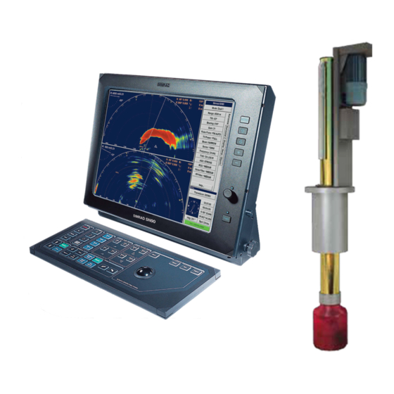
- Page 1 Installation manual Simrad SX90 Fish finding sonar www.simrad.com T E C H N O L O G Y F O R S U S T A I N A B L E F I S H E R I E S...
- Page 3 Simrad SX90 Installation manual This document provides the necessary information of how to install the Simrad SX90 Fish finding sonar. The information must be regarded as general guidelines and recommendations only. The installation shipyard must design and manufacture installation hardware to fit the SX90 Fish finding sonar on each individual vessel.
- Page 4 Support If you require maintenance on your Simrad product contact your local dealer. You can also contact us using the following address: simrad.support@simrad.com. If you need information about our other products, visit www.simrad.com. On our web site you will also find a list of our dealers and distributors.
-
Page 5: Table Of Contents
Installation manual Table of contents ABOUT THIS MANUAL ............. 11 SIMRAD SX90 FISH FINDING SONAR......13 Basic information ....................13 Main units.......................14 Wheelhouse units..................14 Sonar room units..................15 Installation procedure .....................16 System diagram ......................18 Scope of supply ......................19 Additional required items ..................19 Colour display .................... - Page 6 Simrad SX90 Sonar trunk installation principles................38 Sonar trunk installation measurements..............41 HULL UNIT INSTALLATION ..........42 Hull unit models overview ..................43 How to unpack the hull unit from its transport box ..........44 Hull unit mounting ....................45 Bleeding air cock....................47 Mechanical support ....................47 Transducer alignment .....................47...
- Page 7 Installation manual Connect AC mains to the Motor Control Unit ..........86 Connect the Transceiver Unit to the Motor Control Unit........ 87 Connect AC mains to the Heat Exchanger ............ 88 Connect the Ethernet cable for scientific output..........89 Connect cable to external audio system ............89 Transducer cable..................
- Page 8 Simrad SX90 Installation procedures ..................131 Connecting the speed log................131 Connecting the course gyro ............... 133 Test procedures.....................134 Speed log interface test ................134 Course gyro interface setup and test ............136 Positioning system interface setup and test ..........137 Echo sounder system interface setup and test ..........
- Page 9 Installation manual Page 2 ...................... 166 SX92 Mounting trunk dimensions ...............167 Page 1 ...................... 167 Page 2 ...................... 168 SX93 Mounting trunk dimensions ...............169 Page 1 ...................... 169 Page 2 ...................... 170 SX90/SX91 Optional trunk dimensions ...............171 SX92 Optional trunk dimensions .................172 SX93 Optional trunk dimensions .................173 SX90/SX91 Blind cover dimensions..............174 SX92 Blind cover dimensions ................175...
- Page 10 Simrad SX90 Echo sounder system interface ..............191 Trawl system interface ................191 Catch monitoring system interface ............. 192 Current meter interface................193 Radio buoys connection interface............... 193 Cable drawings .....................194 Interface Unit to Processor Unit ..............195 Commercial cable with mini-jack .............. 196 Interface Unit serial lines ................
- Page 11 Installation manual GLL Geographical position latitude/longitude ..........223 HDM Heading, magnetic................223 HDT Heading, true ................... 223 MWD Wind direction and speed ..............223 MWV Wind speed and angle ..............224 TTM Tracked target message..............224 VBW Dual ground and water speed ............225 VTG Course over ground &...
- Page 12 Simrad SX90 307531/C...
-
Page 13: About This Manual
ABOUT THIS MANUAL Purpose The purpose of this manual is to provide the information and basic drawings required for installation of the Simrad SX90 Fish finding sonar system. About these instructions The manual is intended for technical personnel, engineers and naval architects. - Page 14 Simrad SX90 References Refer to the following manuals for additional information about the Simrad SX90 sonar system. Order numbers in brackets. All documents can be downloaded from our web site http://www.simrad.com. • Simrad SX90 Installation Manual, English [307531] • Simrad SX90 Operator Manual, English [307672] •...
-
Page 15: Simrad Sx90 Fish Finding Sonar
Simrad SX90 Fish finding sonar SIMRAD SX90 FISH FINDING SONAR Study this chapter to familiarize yourself with the Simrad SX90 Fish finding sonar system. Topics • Basic information on page 13 • Main units on page 14 • Installation procedure on page 16 •... -
Page 16: Main Units
Processor Unit Microsoft Windows XP® operating system. The software and hardware has been modified by Simrad to suit the SX90 sonar requirements. The purpose of this computer is to allow you to control the sonar. It provides the graphic presentation of... -
Page 17: Sonar Room Units
Beamformer Unit Microsoft Windows XP® operating system. The software and hardware has been modified by Simrad to suit the SX90 sonar requirements. The purpose of this computer is to perform the advanced signal processing required to present the information on the Processor Unit. -
Page 18: Installation Procedure
Installation procedure The Simrad SX90 Fish finding sonar system is a complex and advanced product for professional use. Note In order to obtain maximum safety and performance, it is very... - Page 19 Simrad SX90 Fish finding sonar authorities. The trunk penetrates the hull, and it is therefore a crucial part of the hull unit assembly. Refer to Sonar trunk installation on page 36. Install the hull unit. Due to its physical size and weight, and the fact that the trunk penetrates the vessel hull, it is very important that the hull unit is installed and secured properly.
-
Page 20: System Diagram
Simrad SX90 System diagram Figure 1 SX90 System diagram SX90 Items Processor Unit Beamformer Unit Colour display Operating Panel Interface Unit Transceiver Unit Motor Control Unit Hull Unit Transducer 307531/C... -
Page 21: Scope Of Supply
• Speed log • Course gyro Colour display The Simrad SX90 Fish finding sonar requires a VGA or DVI colour display with a resolution of at least 1280 x 1024 pixels. Uninterrupted Power Supply (UPS) In order to ensure continuous operation of the Simrad SX90 independent of varying quality of the vessel’s mains supply, the... - Page 22 Simrad SX90 Figure 2 NetPro UPS units The UPS units are not included in the SX90 standard delivery. We recommend that the following UPS units are used: Wheelhouse UPS unit • Manufacturer: GE Digital Energy • Model: NetPro NP1000 • Output power: 1000 VA / 600 W •...
-
Page 23: Installation Trunk
The installation trunk required for the hull unit installation is not included in the SX90 standard delivery. The installation trunk may be fabricated by the shipyard, or supplied by Simrad as an option. The mechanical drawings of the trunk and blind cover are included in this manual. -
Page 24: Optional Hull Units And Installation Trunks
310279 (* = SX92 is the standard hull unit) Note The Simrad SX90 and Simrad SX91 hull units and trunks are discontinued. They are only delivered on special order. Installation trunks The installation trunk may be fabricated by the installation shipyard, or supplied by Simrad. -
Page 25: Optional Functionality
Simrad SX90 Fish finding sonar Note The Simrad SX90 and Simrad SX91 hull units and trunks are discontinued. They are only delivered on special order. Optional functionality Extended range Due to international regulations, sonars with operational range exceeding 5000 meters can only be exported on license. For this reason the standard range on the SX90 has been limited to 4500 meters. - Page 26 Simrad SX90 Differential Global Positioning System ((D)GPS) A (D)GPS may be interfaced with the Simrad SX90 sonar to establish the vessel’s position and provide cursor and marker latitude and longitude. In addition to navigational data, the (D)GPS may also be used for the input of speed log information.
-
Page 27: Optional Audio Output
Beamformer Unit. About the audio output The audio output on the Simrad SX90 Fish finding sonar is a line output, and no power amplifier is provided to create sound. The audio output must therefore be connected to a powered audio system. - Page 28 Simrad SX90 Powered speaker system for PC use A commercial powered speaker system for PC use can be obtained from almost any kind of shop for electric appliances, home stereo or computers. Figure 3 Sonar audio using powered speaker system for PC The number of speakers, size and power output can be selected to suit the crew preferences.
-
Page 29: General Supply Conditions
If any damage to the equipment is discovered, the recipient should notify both the transportation company and Simrad so that Simrad can arrange for replacement or repair of the damaged equipment. Once unpacked, the equipment must be stored in a controlled environment with an atmosphere free of corrosive agents, excessive humidity or temperature extremes. -
Page 30: General Installation Requirements
-15% to +20% of the nominal voltage (except under fault conditions). Simrad recommends that the SX90 Fish finding sonar is powered using an Uninterruptable Power Supply (UPS) with sine wave output. The UPS must have the capacity to independently maintain power to the system for a minimum of 10 minutes. -
Page 31: Dry Docking
Simrad SX90 Fish finding sonar Dry docking Make sure that ample clearance under the sonar trunk and/or protection blister is provided when dry docking the vessel. Avoid locating supporting blocks or structures in the vicinity of this equipment. Note The location of the transducer and/or protection blister must be noted on the vessel’s docking plan for future reference. -
Page 32: Installation Planning
Simrad offers free advice for installation planning. Proposed arrangements may be sent for commentary or suggestions supplied by Simrad. The following drawings should be submitted should assistance be requested: • General arrangement • Body plan and drawings of relevant bottom tanks and cofferdams •... -
Page 33: Location Of The Hull Unit
The hull unit should preferably be located within 1/3 to 1/10 of the vessel’s Length Between Perpendiculars (LBP) from its Forward Perpendicular (FP). Deviations should not be made without consulting Simrad. Athwartships The hull unit may be located on the Centre Line (CL) of the vessel, or alongside its keel. -
Page 34: Sonar Room Requirements
Simrad SX90 • Main or bilge keels • Zinc anodes • Cooling elements protruding from the hull • Equipment such as sonar transducers and pilot tubes • Sea chests • Overboard discharges • Dents in the hull All appendages to the hull, indentations and pipe in/outlets are potential sources of underwater noise. - Page 35 Installation planning Insulation Bulkheads must be insulated and provided with an interior wall to the deck. The insulation should be the minimum equivalent of 50 mm of rock-wool. In addition, piping passing through the space prone to condensation must be insulated. Ventilation The sonar room must be connected to the vessel’s ventilation system.
-
Page 36: Sonar Room Arrangement Example
Simrad SX90 Sonar room arrangement example These drawings illustrate a typical sonar room with ample space for hull unit, transceiver unit and personnel. Figure 6 Sonar room arrangement example, top view 307531/C... - Page 37 Installation planning Figure 7 Sonar room arrangement example, side view 307531/C...
-
Page 38: Sonar Trunk Installation
Simrad SX95 Hull Unit installation manual. A trunk with a blind cover – approved by Det norske Veritas (DnV) – can be ordered from Simrad as an optional delivery, or it may be manufactured by the installation shipyard based on the drawings in this manual and the properties of the hull. -
Page 39: Mounting The Sonar Trunk
Sonar trunk installation • SX93 Blind cover dimensions on page 176 Mounting the sonar trunk The location of the sonar trunk must be carefully selected. Note Note the orientation of the centre line of the trunk with regard to the mounting bolts. Remove the gasket on the top flange during welding. -
Page 40: Sonar Trunk Protection
Simrad SX90 Note In order to obtain optimal sonar performance, the total height of the trunk must be as close as possible to its stated minimum height. The top flange must be parallel to the construction water line in both the fore-and-aft and athwartship directions. - Page 41 Sonar trunk installation Figure 9 Installation of a trunk with open blister 307531/C...
- Page 42 Simrad SX90 Figure 10 Installation of a trunk with oil filled blister 307531/C...
-
Page 43: Sonar Trunk Installation Measurements
Sonar trunk installation Sonar trunk installation measurements For future reference, the measurements “A”, “B”, “C” and “D” from the drawing must be made and noted in the table below. Table 3 Trunk installation measurements Millimeters Inches “A” “B” “C” “D” 307531/C... -
Page 44: Hull Unit Installation
This installation manual does not describe the installation of the SX95 Hull Unit. For information about that particular hull unit, refer to the dedicated Simrad SX95 Hull Unit installation manual. The hull unit is a crucial part of the sonar system. Due to its... -
Page 45: Hull Unit Models Overview
SX92: This is the "standard" hull unit for the SX90 sonar. It has 1.2 m stroke length, and it is designed for maximum speed 24 knots. It will fit on a standard Simrad trunk with 680 mm pitch centre diameter. -
Page 46: How To Unpack The Hull Unit From Its Transport Box
SX93: This hull unit has 1.6 m stroke length, and it is designed for maximum speed 20 knots. It will fit on a standard Simrad trunk with 680 mm pitch centre diameter. • SX95: This hull unit has 1.0 m stroke length, and it is designed for maximum speed 12 knots. -
Page 47: Hull Unit Mounting
Hull unit installation Note Do not remove the transducer protection (C) from the transducer until just before the hull unit is lowered onto the mounting trunk. Figure 13 Use the correct lifting eye! There are two lifting eyes on each side of the hull unit: one on the hoisting unit and one on the top of... - Page 48 Simrad SX90 Figure 14 Orientation of the hull unit Note The Motor Control Unit must never be physically dismounted from the Hull Unit. Hull unit mounting procedure To make sure that the procedure is followed, tick off each task after it has been done.
-
Page 49: Bleeding Air Cock
Hull unit installation Bleeding air cock To avoid damage to the transducer by the transmission in air inside the trunk, Figure 15 Bleeding a pipe with a minimum inside diameter air cock of 10 mm must be attached to the air bleeding cock. -
Page 50: Hull Unit Installation Check List
Simrad SX90 Transducer alignment is performed in the SX90 Processor Unit by rotating the echo presentation on the display. This is described in section Alignment of the sonar picture on page 122. Hull unit installation check list Perform a close visual inspection of the sonar room and the physical installation of the hull unit. -
Page 51: Transceiver Unit Installation
Transceiver unit installation TRANSCEIVER UNIT INSTALLATION This chapter explains how to install the Simrad SX90 Transceiver Unit. It is normally positioned in a sonar room close to the hull unit. Topics • Transceiver Unit preparations on page 49 • Transceiver Unit installation procedure on page 49 Related topics •... - Page 52 Connect the grounding cable from the Transceiver Unit to the mounting bracket. Figure 16 Installation of mounting brackets (1) Deckhead Bulkhead Deck Angle bars with threaded holes for shock absorbers. These bars are supplied by Simrad. 307531/C...
- Page 53 Figure 17 Installation of mounting brackets (2) Deckhead Bulkhead Deck Angle bars with threaded holes for shock absorbers. These bars are supplied by Simrad. Minimum 150 mm to closest deckhead and/or bulkhead Recommended distance between 1100 and 1200 mm. Minimum distance 300 mm. Approximately 40 mm.
- Page 54 Simrad SX90 Figure 18 Installation of transceiver Upper shock absorber Transceiver Unit Heat Exchanger Grounding cable Grounding cable, detail 307531/C...
-
Page 55: Wheelhouse Units Installation
Wheelhouse units installation WHEELHOUSE UNITS INSTALLATION This chapter explains how to install the Simrad SX90 hardware units normally positioned in the wheelhouse. These units include: • Processor Unit • Beamformer Unit • Interface Unit • Colour display • Operating Panel... - Page 56 Location of the Operating Panel The Operating Panel provided with the Simrad SX90 contains all the controllers for the sonar operation. The built-in trackball allows you to operate the menu system on the sonar, but additional “short-cut”...
- Page 57 Wheelhouse units installation Location of the Beamformer Unit The Beamformer Unit should be installed inside a console, in a cabinet or on a desk. Make sure that adequate ventilation is available to avoid overheating. The compass safe distances to be allowed for when planning the unit’s location are: •...
-
Page 58: Maximum Distances Between The Units
Simrad SX90 Maximum distances between the units Observe the maximum distances between the wheelhouse units. Figure 19 Maximum distances between the wheelhouse units All measurements are in meters. Processor Unit Beamformer Unit Interface Unit Colour display Operating panel Ethernet cable to Transceiver Unit... -
Page 59: Installation Of The Display Unit
Wheelhouse units installation Installation of the display unit Different display units are available as optional equipment. For installation and operation of the chosen display unit, refer to the manual supplied with the unit. Installation procedure To ensure correct operation, tick off every item when the action has been carried out. -
Page 60: Installation Of The Processor Unit
Simrad SX90 Use a 3 mm Allen key to fasten the four special bolts. Mount the bolt covers in the four corners of the Operating Panel. Related topics • Maximum distances between the units on page 56 • Operating Panel dimensions on page 160... -
Page 61: Installation Of The Beamformer Unit
Wheelhouse units installation Figure 21 Installation of the Processor Unit Computer assembly Locking pin Mounting frame with shock absorbers Fastening screws Related topics • Maximum distances between the units on page 56 • MC80 Processor Unit dimensions on page 158 Installation of the Beamformer Unit The Beamformer Unit should be mounted on the deck or shelf inside a console, cabinet or desk. -
Page 62: Installation Of The Interface Unit
Simrad SX90 Place and secure the mounting frame with six bolts or screws to the basement. The diameter of the holes are 7 mm. Re-attach the computer unit to the mounting frame by guiding it backwards until the locking pins at the bottom of the computer assembly find the correct positions. -
Page 63: Installation Of The Audio System
Wheelhouse units installation Installation procedure To ensure correct operation, tick off every item when the action has been carried out. Prepare the mounting location. Mount the Interface Unit vertically with four fastening screws on the attachment lugs. The diameter of the four fastening holes are 7 mm. -
Page 64: Ups Installation
Simrad SX90 UPS INSTALLATION In order to ensure continuous operation of the Simrad SX90 independent of varying quality of the vessel’s mains supply, the use of uninterrupted power supplies (UPS) is required. Two UPS units are used. One is used to power the wheelhouse units, while the other is used to power the Transceiver Unit. -
Page 65: Cable Layout And Interconnections
Cable layout and interconnections CABLE LAYOUT AND INTERCONNECTIONS Please find provided the installation procedures and requirements for the Simrad SX90 system cables. These instructions must be used together with the cable plan. Note All electronic installations and corresponding wiring must be in accordance with the vessel’s national registry and corresponding... -
Page 66: Cable Plan
Simrad SX90 Cable plan Figure 24 Wheelhouse cables Wheelhouse items Beamformer Unit Processor Unit Interface Unit Display Unit Operating Panel Uninterrupted Power Supply Ethernet cable to Transceiver Unit Serial interface cables External synchronisation Scientific output (Ethernet) Cables identified with an asterisk (*) are supplied with the sonar. - Page 67 Cable layout and interconnections Figure 25 Sonar room cables Sonar room items Transceiver Unit Uninterrupted Power Supply Motor Control Unit Hull Unit Transducer 3–phase mains Ethernet cable to wheelhouse Ethernet control to Motor Control Unit Transducer cable Cables identified with an asterisk (*) are supplied with the sonar.
-
Page 68: List Of Cables
Simrad SX90 List of cables Sonar cables SX90/C01 AC mains to colour display This cable is provided with the colour display. It is a standard commercial cable. • Connect AC mains to the colour display on page 81 • AC mains with IEC320/C21 on page 206 SX90/C02 AC mains to Processor Unit This cable is provided with the sonar. - Page 69 Cable layout and interconnections • AC mains to Motor Control Unit on page 207 Note This cable can be prepared for installation, but it must NOT be connected to the Motor Control Unit until specifically instructed by the setup procedure. SX90/C07 Operating Panel to ground This cable must be provided by the installation shipyard.
- Page 70 Simrad SX90 • USB on page 210 SX90/C12 Operating Panel “Dual cable” to Processor Unit and Interface Unit This cable is provided with the sonar. It is a special dual cable with one common 15-pin connector leading to two separate 9-pin connectors in the two other ends of the cable.
- Page 71 Cable layout and interconnections • Connect AC mains to the Uninterrupted Power Supply on page 73 • AC mains with IEC320/C21 on page 206 SX90/C17 AC mains to Uninterrupted Power Supply in the sonar room This is a standard AC mains cable. It is provided with the Uninterrupted Power Supply.
- Page 72 Simrad SX90 • Connecting the course gyro on page 133 • Course gyro interface setup and test on page 136 • RS-232 to the Interface Unit on page 200 SX90/C22 Serial line interface The Interface Unit provides a total of seven RS-232 serial lines.
- Page 73 Cable layout and interconnections This cable must be provided by the installation shipyard. It is a CAT-6 Ethernet cable. • Connect the Beamformer Unit to the Transceiver Unit on page 85 • RJ45 Ethernet, straight on page 208 Note It is very important that a CAT-6 (or CAT-7) Ethernet cable is used.
-
Page 74: Cable Procedures
Note that detailed information about cable specifications, termination and connectors are provided in the referenced sections. All cables are provided by Simrad unless otherwise specified. In order to provide for maintenance and to allow for vibration, make sure that some slack is provided for all cables. -
Page 75: Connect Ac Mains To The Uninterrupted Power Supply
Cable layout and interconnections • Connect AC mains to the Heat Exchanger on page 88 • Connect the Ethernet cable for scientific output on page 89 • Connect cable to external audio system on page 89 • Transducer cable on page 90 •... -
Page 76: Connect The Video Cable From The Processor Unit To The Colour Display
Simrad SX90 Connect the video cable from the Processor Unit to the colour display This is a standard commercial cable. It is often physically attached to the display, and terminated in the “computer end” with a male 15-pin Delta connector (VGA) or a special DVI connector. -
Page 77: Connect The Usb Cable From The Operating Panel To The Processor Unit
Cable layout and interconnections Connect the USB cable from the Operating Panel to the Processor Unit This is a standard commercial USB data cable. It connects between the Operating Panel and the Processor Unit. The cable length is 4,5 meters. It has a quadratic USB connector in the Operating Panel end (B-plug), and rectangular USB connector in the Processor Unit end (A-plug). -
Page 78: Connect The Operating Panel "Dual Cable
Simrad SX90 Connect the Operating Panel “Dual cable” This is a special dual cable from the Operating Panel to the Processor Unit and the Interface Unit. This cable has one common 15-pin connector leading to two separate 9-pin connectors in the two other ends of the cable. The cable is included in the standard delivery, and the cable length is 4,5 meter. -
Page 79: Connect The Two Cables From The Interface Unit To The Processor Unit
Cable layout and interconnections Connect the two cables from the Interface Unit to the Processor Unit These are two special interconnection cables provided with the sonar. Both are 1,2 meters long, and connected permanently to the Interface Unit end.. • Cable communicates the control signals between the Processor Unit and the Interface Unit. -
Page 80: Connect The Processor Unit To The Beamformer Unit
Simrad SX90 Connect the Processor Unit to the Beamformer Unit Procedure This is cable SX90/C30 Locate the 5 meter readily terminated Ethernet cable provided with the Beamformer Unit. Connect the Ethernet cable from slot on the rear side of the Processor Unit to slot on the rear side of the Beamformer Unit. -
Page 81: Connect Ac Mains And Ground To The Processor Unit
Cable layout and interconnections Connect AC mains and ground to the Processor Unit The AC mains cable is a standard commercial item. It is secured to the rear side of the Processor Unit with a bracket. The mains voltage for the Processor Unit is 115 or 230 Vac, and it will automatically sense the current supply voltage. -
Page 82: Connect Ac Mains And Ground To The Beamformer Unit
Simrad SX90 Connect AC mains and ground to the Beamformer Unit The AC mains cable is a standard commercial item. It is secured to the rear side of the Beamformer Unit with a bracket. The mains voltage for the Beamformer Unit is 115 or 230 Vac, and it will automatically sense the current supply voltage. -
Page 83: Connect Ac Mains To The Colour Display
Cable layout and interconnections Connect AC mains to the colour display The AC mains cable is a standard commercial item. If the AC mains connector on the cable does not fit, replace it with a suitable connector. Procedure This is cable SX90/C01 Connect the AC mains cable from the Uninterrupted Power Supply in the wheelhouse to the colour display. -
Page 84: Connect Ac Mains To The Transceiver Unit
Simrad SX90 Connect AC mains to the Transceiver Unit The AC mains cable is a standard commercial item. It is connected to a socket at the bottom of the Transceiver Unit. If the AC mains connector on the cable does not fit, replace it with a suitable connector. -
Page 85: Connect Ground To The Interface Unit
Cable layout and interconnections Connect ground to the Interface Unit Procedure This is cable SX90/C13 Connect the grounding cable to the Interface Unit. A connection bolt is located on the right hand side of the unit. Related topics • Vessel ground on page 205 307531/C... -
Page 86: Connect Ground To The Operating Panel
Simrad SX90 Connect ground to the Operating Panel Procedure This is cable SX90/C06 Connect the grounding cable to the Operating Panel. A connection bolt is located under the unit. • Vessel ground on page 205 Figure 34 Ground connection on the Operating Panel... -
Page 87: Connect The Beamformer Unit To The Transceiver Unit
Cable layout and interconnections Connect the Beamformer Unit to the Transceiver Unit Procedure This is cable SX90/C31 Connect the Ethernet cable from the bottom Ethernet socket on slot on the rear side of the Beamformer Unit to the right Ethernet socket under the Transceiver Unit. Note This cable must be provided by the installation shipyard. -
Page 88: Connect Ac Mains To The Motor Control Unit
Simrad SX90 Connect AC mains to the Motor Control Unit This is a special mains cable for 3-phase AC mains. It must be provided by the installation shipyard. Observe the cable specifications, see AC mains to Motor Control Unit on page 207. -
Page 89: Connect The Transceiver Unit To The Motor Control Unit
Cable layout and interconnections Connect the Transceiver Unit to the Motor Control Unit Procedure This is cable SX90/C32 Locate the 8 meters terminated Ethernet patch cable provided with the Transceiver Unit. Connect the Ethernet cable from the Ethernet socket under the Transceiver Unit to the Ethernet socket on the Motor Control Unit. -
Page 90: Connect Ac Mains To The Heat Exchanger
Simrad SX90 Connect AC mains to the Heat Exchanger This is a standard AC mains cable. It is provided readily fixed to the heat exchanger cabinet. If the AC mains connector on the cable does not fit, replace it with a suitable connector. -
Page 91: Connect The Ethernet Cable For Scientific Output
Cable layout and interconnections Connect the Ethernet cable for scientific output Procedure This is cable SX90/C32 Connect the Ethernet cable from the additional Ethernet socket on the rear side of the Processor Unit. Note This cable must be provided by the installation shipyard. Use a commercial CAT–6 cable. -
Page 92: Transducer Cable
Simrad SX90 Transducer cable The transducer cable is provided by Simrad. It is physically connected to the top of the transducer shaft, and terminated in the other end with a large connector. Note Do not mount the flexible transducer cable to the Transceiver Unit. -
Page 93: Rj45 Ethernet, Straight
Cable layout and interconnections • AC mains to Motor Control Unit on page 207 • RJ45 Ethernet, straight on page 208 • VGA/SVGA Display on page 209 • USB on page 210 • DVI–I Display on page 211 • Sonar serial line on page 212 •... -
Page 94: Start-Up Procedures
Simrad SX90 START-UP PROCEDURES The procedures in this chapter shall be carried out once all the hardware units have been installed, and the cabling is finished. Note When you carry out these procedures, make sure that you only perform those tasks described, and in the given order. -
Page 95: Hull Unit Familiarization
Start-up procedures Hull unit familiarization Figure 39 Hull unit familiarization Upper limit switch S304 Transducer shaft Lower limit switch S305 Hand crank for manual hoisting and lowering Hoist motor Brake release screw Motor Control Unit Gantry Mounting flange Installation trunk Transducer Transducer shaft sleeve 307531/C... -
Page 96: Motor Control Unit Familiarization
Simrad SX90 Motor Control Unit familiarization Figure 40 Motor Control Unit familiarization (A) Internal 24 Vdc power supply (B) Ethernet connector (F301) Fuse for internal power supply (E301) Terminal strip for AC mains input (K301) Hoisting contactor (K302) Lowering contactor... -
Page 97: Functional Check
Start-up procedures Functional check Procedure Before you commence with the start-up procedure, check the following items. To make sure that the procedure is followed, tick off each task after it has been done. Check that the 3-phase mains fuses are disconnected in the ship’s fuse box. -
Page 98: Apply 3-Phase Ac Power
Simrad SX90 Apply 3-phase AC power How to apply 3–phase power To make sure that the procedure is followed, tick off each task after it has been done. Figure 41 Motor Control Unit with S301 and E301 Locate the motor protecting switch... -
Page 99: Check The Hoist Motor's 3-Phase Ac Connections
Start-up procedures Check the hoist motor’s 3–phase AC connections Procedure In order to ensure that the hoisting motor operates properly, and to avoid serious damage to the motor, you must check that the motor connections are made in accordance with the supplied 3–phase voltage. -
Page 100: Check The 3-Phase Connection For Correct Rotation Direction
Simrad SX90 Re-insert the 3-phase mains fuses for the hull unit in the vessel’s fuse box. Check the 3–phase connection for correct rotation direction Procedure The Motor Control Unit is equipped with a Phase Watch Relay ), which prevents operation of the hoist/lower motor if K303 the 3-phase connections are wrong with respect to the motor’s... -
Page 101: Check The Contactor Operation
Start-up procedures Check again that the LED on the front of the Phase Watch Relay ( ) is lit. K303 Switch off the motor protecting switch by pressing S301 the operating handle downwards to OFF position. Check the contactor operation Procedure Normally, in this part of the test procedure, the transducer shaft will be in upper position with the upper limit switch activated. -
Page 102: Functional Check To Verify Correct Hoist And Lower Functionality
Simrad SX90 Press the lower limit switch downwards, and S305 check that the contactor is deactivated while activating the switch. Locate the hand crank inside the Motor Control Unit. Remove the hand crank from its storage position, and check that the contactor is deactivated. Do not place the hand crank back into its storage position. - Page 103 Start-up procedures Check the training direction of the hoist/lower motor by very briefly pressing the hand crank safety switch S303 If the transducer shaft was hoisted, perform the following procedure: Disconnect the vessel’s 3-phase mains fuses. Change two of the 3-phase connections in the mains connection box on the motor.
-
Page 104: Starting Up The Wheelhouse Units
Simrad SX90 Switch off the motor protecting switch by pressing S301 the operating handle downwards to OFF position. The hull unit is now ready for further cabling (Ethernet cable to the transceiver unit for hoist/lower control) and system testing. The system test is provided in the relevant sonar installation manual. - Page 105 Start-up procedures Figure 46 Front of Processor and Beamformer Units with S101 Observe that the green LED next to the button Power on the Operating Panel starts blinking. • The sonar is now loading up the sonar program. After approximately two minutes, the sonar menu will be displayed.
-
Page 106: Checking The Operating Panel
Simrad SX90 • If not, check that the tilt angle in the upper left-hand corner is set to 0 degrees. Checking the Operating Panel The simulated echoes makes it possible to test out most of the operational functions without starting up the Transceiver Unit. - Page 107 Start-up procedures Check that a numbered triangle appears in the position of the cursor. Check the Own Ship Marker. Press the button. Own Ship Marker Check if a square symbol appears at the ship’s symbol. Remove Target Marker and Ship Marker. Use the trackball to move the cursor to the Objects on the right-hand side of the menu.
- Page 108 Simrad SX90 Check that a Circle marker appears next to the ship symbol. Press again to bring up the Ship Marker at the ship symbol. Press a third time to remove the Circle marker. Modes By means of the four...
- Page 109 Start-up procedures Check that the Range read-out in the menu and Horizontal on the top of the tilt indicator changes accordingly. Vertical gain Check the vertical gain read-outs. Press the button to select mode 270°/Vertical. Mode 2 Select mode 270°/Vertical. Click the tab to bring up this menu.
- Page 110 Simrad SX90 Check that the menu disappears for a full screen echo presentation. Press the button once again to recall the menu. View menu menu is a short-cut menu that appears next to the cursor View to offer specific functions.
- Page 111 Start-up procedures Check that the tilt read-out in the menu corresponds with the tilt indicator shown in the top left corner of the display. Press the button in the Tilt field. Auto Check that the tilt limits appear on the tilt indicator shown in the top left corner of the display.
- Page 112 Simrad SX90 Observe that the ship symbol has been returned to the centre of the display. Training Observe this procedure to check the training function, as well as position and target track. Press the (arrow) buttons in the Train left Train right Train field repeatedly.
- Page 113 Start-up procedures 12 Check that the audio line starts a search within the displayed sector limits. 13 Press the button to stop the search. Manual Operating Panel backlight The background light in the Operating Panel can be adjusted on menu. Display Click the tab to open the...
-
Page 114: Starting Up The Transceiver Unit
Simrad SX90 Starting up the Transceiver Unit Observe this procedure to power up the Transceiver Unit for the first time. Figure 48 SX90 Transceiver Unit power supplies Fuses F1 and F2 on the power supply PSU Main Service switch Indicator lamps for low voltage supplies... -
Page 115: Checking The Hoist/Lower System
Start-up procedures Check that the service switch (B) on the power PSU Main supply is in OFF (middle) position. Connect the mains power cable to the mains connector at the bottom of the Transceiver Unit. Check that the lamps marked (C) on the 3,3V power supply are lit. -
Page 116: Preparations
Beamformer Unit on the bridge is connected. Select the hull unit to be used The Simrad SX90 Fish finding sonar can be provided with several different hull units. Observe the following procedure to define which hull unit that is used on the sonar. -
Page 117: Checking The Bridge Functions
Start-up procedures On the menu, click the button to Test Installation menu switch the menu off. Checking the bridge functions Note This procedure must be performed simultaneously with the next procedure; “Checking the sonar room functions”. The instructions marked [Sonar room] are performed in the sonar room. - Page 118 Simrad SX90 Check that the LED next to the button starts to Down flash, and that the audible signal indicates transducer movement. When lower position has been reached, check that the LED next to the button illuminates continuously, Down that the audible signal stops, and that the upper button in the menu shows Transducer: DOWN.
- Page 119 Start-up procedures When upper position has been reached, check that the LED next to the button illuminates continuously, that the audible signal stops, and that the upper button in the menu shows Transducer: UP. Status 11 Notify the sonar room to perform the next step. 12 [Sonar room] Set the hoist/lower switch in the Motor S302...
-
Page 120: Checking The Sonar Room Functions
Simrad SX90 Checking the sonar room functions Note This procedure must be performed simultaneously with the procedure and checklist in the previous chapter; “Checking the bridge functions”. The instructions marked [Bridge] are performed on the bridge. Note that those procedures are more detailed that what is presented here. -
Page 121: Starting Up The Sonar System
Start-up procedures Click to select the menu settings. Noise & VR Noise test • After the preparations described above has been carried out, the echo level for the selected audio beam will be displayed in the button in Echo Level menu. -
Page 122: Preparations
Simrad SX90 The following two procedures must be performed simultaneously by the person on the bridge and the person in the sonar room: • Actions on the bridge shall be performed on the bridge. • Actions in the sonar room shall be performed in the sonar room. -
Page 123: Actions On The Bridge
Start-up procedures Actions on the bridge Note This procedure must be performed simultaneously with the next procedure; “Actions in the sonar room”. The instructions marked [Sonar room] are performed in the sonar room. Start up the sonar. Check that the depth is sufficient for lowering of the transducer. -
Page 124: Actions In The Sonar Room
Simrad SX90 Actions in the sonar room Note This procedure must be performed simultaneously with the procedure and checklist in the previous procedure; “Actions on the bridge”. The instructions marked [Bridge] are performed on the bridge. Note that those procedures are more detailed that what is presented here. - Page 125 Start-up procedures Figure 49 Hull unit alignment How to align the sonar picture In order to make a correct alignment, a particular target such as a buoy is required. Locate the 0 degrees transducer mark. Estimate the approximate alignment angle (0 to 360 degrees) clockwise from the bow to the 0 degrees transducer mark.
-
Page 126: Adjusting The Stabilisation Sensor Offset
Simrad SX90 Check that the Offset is 0 degrees. If it is not, adjust to 0 degrees. Click the button. Alignment Enter the estimated alignment angle. Check that the echo picture on the display is correct in relation to the ambient situation. -
Page 127: Defining Own Ship Parameters
Start-up procedures Estimate the approximate offset angle (0 to 360 degrees) clockwise from the 0 degrees transducer mark to the 0 degrees reference stabilisation mark. • The angle between each mounting bolt can be used as an aid; – 20 bolts version: 18 degrees between each bolt. –... -
Page 128: Specify Instrument Position Offsets
Simrad SX90 Specify instrument position offsets In order to get correct references of the instruments, the position of the sonar transducer and the GPS antenna must be set relative to the origo definition. The origo is initially positioned at the vessel’s stern. This is... - Page 129 Start-up procedures 11 Click the button and enter the correct value. X Position 12 Click the button and enter the correct value. Y Position 13 Click to finish. Close When a new display mode is selected, the instruments will change to the chosen positions. 307531/C...
-
Page 130: Interfacing Peripheral Equipment
Simrad SX90 INTERFACING PERIPHERAL EQUIPMENT The physical connections of the peripheral sensors has been previously described. This chapter describes how the sonar system shall be set up to accept the signals from the sensors, and how you can verify that the various interfaces are fully functional. -
Page 131: How To Change The Interface Settings
Interfacing peripheral equipment Table 5 Default interface settings (cont’d.) Type Port Baudrate Talker Sensor — — — — Stabilisation sensor — Weather Wind 4800 None How to change the interface settings To it becomes necessary to change any of the interface settings, observe the following procedure. -
Page 132: How To Monitor The Traffic On A Serial Line
Simrad SX90 Move the cursor down on the sub-menu, but do not press the button on the Operating Panel. Select Observe that each sensor has a secondary sub-menu listing the default choices or None. The chosen setting is marked. Click None if you wish to disable the sensor input. -
Page 133: Installation Procedures
Interfacing peripheral equipment Click the + sign in front of the serial port you wish to monitor. Click the COM symbol under the serial port. Observe the transmit and receive data on the right hand side of the dialogue. Figure 54 Object Inspector dialog box, sensor I/O control dialogue will display the transmit and Object Inspector receive data currently handled by the selected communication... - Page 134 Simrad SX90 • Pulse log (200 pulses/nautical mile) For any type of pulse log output (relay, open collector, or optocoupler), the output must be free from other connections. This means that on the speed log output to be used, only the sonar can be interfaced.
-
Page 135: Connecting The Course Gyro
Interfacing peripheral equipment Note The output from a pulse log must never be connected to more than one system simultaneously. If it is connected to the sonar, do not use the same output to feed other systems. Procedure Connect the speed log as described. Test the interface. -
Page 136: Test Procedures
Simrad SX90 • LR40 Digital Gyro Repeater The LR40 Digital Gyro Repeater can be provided by Simrad on part number 298-078535. Connect the serial line to any vacant port (TB1-7) in the Interface Unit as described in section RS-232 to the Interface Unit on page 200. For connections to the LR40 Digital Gyro Repeater, refer to the LR40 Instruction Manual. - Page 137 Interfacing peripheral equipment On the menu, select I/O Setup Sensors →Speed →Speed Log Observe that the parameter dialog appears at Sensor Config the bottom of the menu field. Check that the settings in the parameter dialog Sensor Config correspond to the sensor settings table. Note The pulse log must use serial port number 9.
-
Page 138: Course Gyro Interface Setup And Test
Simrad SX90 Change the settings in the parameter dialogue Sensor Config to suit your requirements for the serial line. Remember to set correct baud rate, and set to GP. Talker Click to exit the parameter dialogue. Close Sensor Config Check that the speed read-out in the... -
Page 139: Positioning System Interface Setup And Test
Interfacing peripheral equipment (D)GPS heading data (RS-232 serial line interface) If the GPS is used for the course gyro input, wait with this test until the GPS position data are tested. When required, use the following procedure for testing the GPS input. Access the menu. -
Page 140: Trawl System Interface Setup And Test
• To access this menu, see How to change the interface settings on page 129. On the menu, select I/O Setup Sensors →Trawl system • Select to check the interface to the Simrad ITI →ITI system • Select to check the interface to the Simrad →FS3300 FS20/25 and FS70 systems. -
Page 141: Catch Monitoring Interface Setup And Test
129. On the menu, select I/O Setup Sensors →Trawl system • Select to check the interface to the Simrad ITI →ITI system • Select to check the interface to the Simrad PI30, →PI30 PI32, PI44 or PI54 systems. -
Page 142: Current Meter Interface Setup And Test
Simrad SX90 On the menu, select I/O Setup Sensors →BuoySystem →Buoy NMEA Observe that the parameter dialogue appears Sensor Config at the bottom of the menu field. Change the settings in the parameter dialogue Sensor Config to suit your requirements for the serial line. -
Page 143: Final Tests And Measurements
Final tests and measurements FINAL TESTS AND MEASUREMENTS In order to verify that the sonar works properly, the following measurements and tests must be carried out: • Source level measurements • Receiving voltage response measurements • Noise/speed curve Required equipment To carry out these tests and measurements, an oscilloscope, a signal generator and a test hydrophone must be available. -
Page 144: Preparations
Simrad SX90 Figure 56 Test setup P4 on TRX32 board no.8 (far right) Oscilloscope Trigger input Hydrophone input Hydrophone Preparations Fill in the test hydrophone data in the table provided. Lower the test hydrophone into the water, and adjust the depth so that it matches the transducer array. -
Page 145: Test Procedure
Final tests and measurements Test procedure Observe the following procedure to make the source level measurements. Connect the hydrophone and pulse to the TX Enable oscilloscope as shown in the test schematics. Ensure that the distance between the transducer and the hydrophone is between 5 and 20 meters depending on the size of your vessel. -
Page 146: Source Level Test Results
Simrad SX90 Note Do not remove the hydrophone from the position used for the source level measurements. This known position should also be used for the receiving voltage response (VR) measurements in the next section. Source level test results The two tables created for the test results are provided below. -
Page 147: Receiving Voltage Response (Vr) Measurements
Final tests and measurements Receiving voltage response (VR) measurements In order to measure the receiving voltage response, use the test hydrophone in the same position as for the previous source level measurements. Preparations Use the following menu settings on the sonar. Open the menu. -
Page 148: Finalizing The Procedure
Simrad SX90 10 Retrieve the Hydrophone sensitivity as transmitter S from the Test hydrophone data table. 11 Enter the data into the Receiving voltage response (VR) table. 12 Retrieve the 20logR value from the Measurements results table. 13 Enter the data into the Receiving voltage response (VR) table. -
Page 149: Noise/Speed Curve Measurements
Final tests and measurements Noise/speed curve measurements This section explains how to create a noise/speed curve for the sonar installation. Preparations In order to make a noise/speed curve for the ship, make the following settings in the sonar menu. Open the menu. - Page 150 Simrad SX90 this high noise level is caused by flow noise from the vessel’s hull or by the engine/propeller, perform the following test. By comparing these three resulting plots it should be possible to sort out if the main noise is caused by flow noise or engine/propeller noise.
- Page 151 Final tests and measurements Table 12 Noise verification Bearing is 0° for all measurements Speed Stable speed Acceleration Retardation 0 knots 2 knots 4 knots 6 knots 8 knots 10 knots 12 knots 14 knots 16 knots 307531/C...
- Page 152 Simrad SX90 Table 13 Noise/Speed plot 307531/C...
-
Page 153: Technical Specifications
Technical specifications TECHNICAL SPECIFICATIONS This chapter provides the technical specifications and requirements related to the Simrad SX90 Fish finding sonar Topics • Power specifications on page 151 • Weights and outline dimensions on page 152 • Environmental specifications on page 153... -
Page 154: Weights And Outline Dimensions
Simrad SX90 Transceiver Unit • Voltage: – Nominal: 115 / 230 Vac, single phase (automatic) – Deviation: 15 % of nominal voltage – Transient: 20 % of nominal voltage, recover time 3 s • Power consumption: 600 VA • Frequency: 47 to 63 Hz Hull Unit •... -
Page 155: Environmental Specifications
Technical specifications • Dimensions (WDH): 520 x 505 x 750 mm (including shock absorbers) SX90 / SX91 / SX92 / SX93 Hull Units • Weight: – SX90: Approximately 850 kg – SX91: Approximately 900 kg – SX92: Approximately 850 kg –... - Page 156 Simrad SX90 Beamformer Unit MC81 • Operational temperature: 0 to +40°C • Storage temperature: -40 to +70°C • Humidity: 5 to 95% non-condensing Operating Panel • Not applicable. Interface Unit • Not applicable. Display Unit • Not applicable. Refer to the documentation for the chosen display.
-
Page 157: Drawing File
They are not in scale. All dimensions are in mm unless otherwise is noted. The original installation drawings are available on PDF and/or AutoCad’s DWG format. Visit www.simrad.com to download. Cabinet outline dimension drawings • Transceiver Unit dimensions on page 156 •... -
Page 158: Transceiver Unit Dimensions
Simrad SX90 Transceiver Unit dimensions 307531/C... -
Page 159: Interface Unit Dimensions
Drawing file Interface Unit dimensions 307531/C... -
Page 160: Mc80 Processor Unit Dimensions
Simrad SX90 MC80 Processor Unit dimensions 307531/C... -
Page 161: Mc81 Beamformer Unit Dimensions
Drawing file MC81 Beamformer Unit dimensions 307531/C... -
Page 162: Operating Panel Dimensions
Simrad SX90 Operating Panel dimensions 307531/C... -
Page 163: Sx90 Hull Unit Dimensions
Drawing file SX90 Hull unit dimensions 307531/C... -
Page 164: Sx91 Hull Unit Dimensions
Simrad SX90 SX91 Hull unit dimensions 307531/C... -
Page 165: Sx92 Hull Unit Dimensions
Drawing file SX92 Hull unit dimensions 307531/C... -
Page 166: Sx93 Hull Unit Dimensions
Simrad SX90 SX93 Hull unit dimensions 307531/C... -
Page 167: Sx90/Sx91 Mounting Trunk Dimensions
Drawing file SX90/SX91 Mounting trunk dimensions Page 1 307531/C... -
Page 168: 166
Simrad SX90 Page 2 307531/C... -
Page 169: Sx92 Mounting Trunk Dimensions
Drawing file SX92 Mounting trunk dimensions Page 1 307531/C... -
Page 170: 168
Simrad SX90 Page 2 307531/C... -
Page 171: Sx93 Mounting Trunk Dimensions
Drawing file SX93 Mounting trunk dimensions Page 1 307531/C... -
Page 172: 170
Simrad SX90 Page 2 307531/C... -
Page 173: Sx90/Sx91 Optional Trunk Dimensions
Drawing file SX90/SX91 Optional trunk dimensions 307531/C... -
Page 174: Sx92 Optional Trunk Dimensions
Simrad SX90 SX92 Optional trunk dimensions 307531/C... -
Page 175: Sx93 Optional Trunk Dimensions
Drawing file SX93 Optional trunk dimensions 307531/C... -
Page 176: Sx90/Sx91 Blind Cover Dimensions
Simrad SX90 SX90/SX91 Blind cover dimensions 307531/C... -
Page 177: Sx92 Blind Cover Dimensions
Drawing file SX92 Blind cover dimensions 307531/C... -
Page 178: Sx93 Blind Cover Dimensions
Simrad SX90 SX93 Blind cover dimensions 307531/C... -
Page 179: General Safety Rules
Appendix A General safety rules APPENDIX A — GENERAL SAFETY RULES The Simrad SX90 Fish finding sonar system operates on 230 Vac 50/60 Hz. WARNING This voltage is lethal! The following safety precautions must be followed at all times during installation and maintenance work: •... -
Page 180: Equipment Handling
Unless otherwise stated in the accompanying documentation, electronic, electro-mechanical and mechanical units supplied by Simrad can be transported using all methods approved for delicate equipment; (by road, rail, air or sea). The units are to be transported in accordance with general or specific instructions for the appropriate unit(s), using pallets, transport cases, or carton boxes as appropriate. -
Page 181: Storage Prior To Installation Or Use
Appendix B Equipment handling Heavy units may be equipped with lifting lugs for transportation by crane within the workshop or installation area. Before you use a crane: • You must check the applicable weight certificate for the crane. • You must check the security of the lifting lugs. Ensure that all available lifting lugs are used. -
Page 182: Inspection
If any units are damaged, prepare an inspection report stating the condition of the unit and actions taken. Describe the damage and collect photographic evidence if possible. Send the inspection report to Simrad as soon as possible. 307531/C... -
Page 183: Unpacking
Appendix B Equipment handling If the units are not damaged, check the humidity absorbing material. If required, dry or replace the bags, then re-pack the unit(s) according to the packing instructions. Unpacking General unpacking procedure Normal precautions for the handling, transportation and storage of fragile electronic equipment must be undertaken. -
Page 184: Unpacking Electronic And Electromechanical Units
Simrad SX90 Unpacking electronic and electromechanical units Electronic and electromechanical units will normally be wrapped in a clear plastic bag. Lift the unit, in its bag, out of the carton and place it in a stable position on the floor/work bench. -
Page 185: Storage After Unpacking
Appendix B Equipment handling Storage after unpacking The unit must whenever possible be stored in its original transportation crate until ready for installation. The crate must not be used for any purpose for which it was not intended (eg. work platform etc.). Once unpacked, the equipment must be kept in a dry, non condensing atmosphere, free from corrosive agents and isolated from sources of vibration. -
Page 186: Mechanical Units
Cables Wipe clean all exposed cables, and check for damage. If a cable shows signs of wear or ageing, contact Simrad for advice. Internal batteries If the unit contains batteries, these may discharge slowly during storage. -
Page 187: Dehumidifier
Appendix B Equipment handling A suitable piece of insulating material can be placed between the battery and the electrical contacts to prevent electrical discharge. The battery can then remain in the unit, reducing the risk of it being misplaced during the storage period. Caution Units containing lithium or alkaline batteries must be handled separately and with care. -
Page 188: Circuit Board Handling And Packaging
Simrad SX90 Must not be transported or stored in temperatures below -5 degrees Celsius. Other units can normally be stored in temperatures between -30° C and +70° C, refer to the system’s technical specifications for details. Unless otherwise specified, transducers must not be stored in temperatures below -20°... -
Page 189: Returning A Circuit Board
Appendix B Equipment handling Unpacking on board the vessel When you are working on board a vessel, an “approved conductive service mat” is often far away. As you still need to unpack circuit boards, make sure that you do it in the instrument room, or at another location where you have a steel deck. - Page 190 Simrad SX90 • The working area must be covered by an approved conductive service mat that has a resistance of between 50 kΩ and 2 MΩ, and is connected directly to a reliable earth point via its earthing cord. • The service personnel involved must wear a wristband in direct contact with the skin, connected to the service mat.
-
Page 191: Csx90 Cable Details
• Number of cores System and shipyard cables Cables fall into two categories. • System cables: These cables are supplied by Simrad. • Shipyard cables: These cables must be provided by the shipyard performing the installation, or the shipowner. 307531/C... -
Page 192: Cables To Peripheral Devices
Simrad SX90 Note Simrad accepts no responsibility for damage to the system or reduced operational performance caused by improper wiring. Cables to peripheral devices through in the Interface Unit are all RS-232 serial line connections. These may be used for any of the serial line auxiliary inputs suggested below. -
Page 193: Echo Sounder System Interface
Echo sounder system interface setup and test on page 137 Trawl system interface The Simrad SX90 Fish finding sonar can read the trawl data from a Simrad FS20, FS25 or FS70 Trawl sonar or the Simrad ITI (Integrated Trawl Instrumentation) system. The communication is achieved using a RS-232 serial line. -
Page 194: Catch Monitoring System Interface
Catch monitoring system interface To provide purse seine depth information on the sonar’s display, one of the Simrad catch monitoring systems may be connected. You can also interface a third party catch monitoring system. Connect the serial line to any vacant port (TB1-7) in the Interface Unit as described in section RS-232 to the Interface Unit on page 200. -
Page 195: Current Meter Interface
Unit on page 200. Related topics • Current meter interface setup and test on page 140 Radio buoys connection interface The Simrad SX90 can read the data from one of the following GPS based radio buoy systems: • SERPE • Ariane • Ryokusei All these systems are interfaced by means of an RS-232 serial line. -
Page 196: Cable Drawings
Simrad SX90 Cable drawings The drawings provided specify in detail each cable used by the SX90 Fish finding sonar. Cable specifications • Interface Unit to Processor Unit on page 195 • Commercial cable with mini-jack on page 196 • Interface Unit serial lines on page 197 •... -
Page 197: Interface Unit To Processor Unit
Appendix C SX90 cable details Interface Unit to Processor Unit Two cables are used to provide data and control transfer between the Interface Unit and the Processor Unit. Both cables are physically attached to the Interface Unit. Note that the length of these cables are limited to 1.2 meters each. -
Page 198: Commercial Cable With Mini-Jack
Simrad SX90 Commercial cable with mini-jack This is a commercial cable. The mini-jack connects to the audio output (green) on the rear side of the Beamformer Unit. The other end must be terminated to fit the audio system input socket. -
Page 199: Interface Unit Serial Lines
Appendix C SX90 cable details Interface Unit serial lines The Interface Unit provides seven serial line communication ports. These are available on terminal blocks through and all are identical. For connection to the peripheral units, refer to the applicable documentation for the unit in question. These cables are not included with the delivery, and must be provided by the installation shipyard. -
Page 200: Pulse Speed Log Interface
Simrad SX90 Pulse speed log interface This interface has been provided for a pulse speed log. This cable is not included with the delivery, and must be provided by the installation shipyard. Cable specifications • Conductors: 2 x 0.5 mm²... -
Page 201: External Synchronisation Interface
Appendix C SX90 cable details External synchronisation interface This cable allows external synchronisation of the sonar’s transmission. This cable is not included with the delivery, and must be provided by the installation shipyard. Cable specifications • Conductors: 4 x 0.5 mm² •... -
Page 202: Rs-232 To The Interface Unit
Simrad SX90 RS-232 to the Interface Unit This drawings shows how to connect a serial line on the Interface Unit to a remote system using RS-232 interface and a 9–pin D-connector on the remote system. All cables must be provided by the installation shipyard. -
Page 203: Sonar And Iti Communication
Appendix C SX90 cable details Sonar and ITI communication This drawings shows how to connect a serial line on the Interface Unit to a Simrad ITI system using RS-232 interface and a 9–pin ’D’-connector on the ITI system. Note Observe the required settings on the ITI system to activate the interface. -
Page 204: Sonar And Fs20/25 Communication
Sonar and FS20/25 communication This drawings shows how to connect a serial line on the Interface Unit to a Simrad FS20 or FS25 system using RS-232 interface and a 9–pin ’D’-connector on the rear side of the FS20/25 HP/PC Processor Unit system. -
Page 205: Sonar And Pi44/Pi54 Communication
Sonar and PI44/PI54 communication This drawings shows how to connect a serial line on the Interface Unit to a Simrad PI44 or PI54 system using RS-232 interface and a special connector on the rear side of the PI Operator Unit. Note that a suitable plug and cable is provided with the PI system. -
Page 206: Sonar And Pi30/Pi32 Communication
Sonar and PI30/PI32 communication This drawings shows how to connect a serial line on the Interface Unit to a Simrad PI30 or PI32 system using RS-232 interface and a special connector on the rear side of the PI Operator Unit. Note that a suitable plug and cable is provided with the PI system. -
Page 207: Vessel Ground
Appendix C SX90 cable details Vessel ground This cable is used to connect a system unit to the ship’s ground. Note that this cable must be as short as possible. Cable specifications • Conductors: 1 x 6 mm² • Screen: None •... -
Page 208: Ac Mains With Iec320/C21
Simrad SX90 AC mains with IEC320/C21 This is a commercial 230 Vac power cable for 2-phase mains power. One end is fitted with an IEC plug, the other with a standard European mains plug. This is a standard cable type supplied in different lengths. -
Page 209: Ac Mains To Motor Control Unit
Appendix C SX90 cable details AC mains to Motor Control Unit This cable is used to connect 3-phase mains supply and ship’s ground to the hoist/lower motor on the hull unit. The connections are made to the Motor Control Unit. Caution Observe the difference between 230 Vac and 380/440 Vac wiring on the hoist motor! -
Page 210: Rj45 Ethernet, Straight
Simrad SX90 RJ45 Ethernet, straight This cable is used to provide standard Ethernet connections. Note that various categories exists. Normally, Cat.5 and Cat.6 cables are used in local area networks with bandwidth exceeding 100 Mbit. Ethernet cables are available commercially in different lengths, colours and categories. -
Page 211: Vga/Svga Display
Appendix C SX90 cable details VGA/SVGA Display This is a standard VGA and SVGA video cable. One end is normally connected to the display, while the other end is terminated in a standard D-connector. Cable specifications • Conductors: Defined by the manufacturer •... -
Page 212: Usb
Simrad SX90 Just about any computer that you buy today comes with one or more Universal Serial Bus (USB) connectors on the back. These connectors let you attach everything from mouse to printers to your computer quickly and easily. Since the operating system supports USB, installation of device drivers is also easy. -
Page 213: Dvi-I Display
Appendix C SX90 cable details DVI–I Display This cable is a standard DVI-I cable. It is normally provided with the colour display. For more information about the DVI signals, see http://en.wikipedia.org. Signal Signal TMDS Data 2- (Digital red - (Link 1)) Ground (Return for pin 14 and analog sync) TMDS Data 2+ (Digital red + (Link 1)) Hot plug detect... -
Page 214: Sonar Serial Line
Simrad SX90 Sonar serial line This cable is used to provide a two-way communication to a sonar system using an Interface Unit. Cable specifications • Conductors: 9 x 2 x 0.5 mm² • Screen: Screened twisted pairs and overall braided •... -
Page 215: Operating Panel "Dual
Appendix C SX90 cable details Operating Panel “Dual” This cable is used to connect the Operating Panel to the Processor Unit and the Interface Unit. • The 15–pin plug connects to the Operating Panel • The 9–pin female plug connects to the Processor Unit •... -
Page 216: Dbasic Cable Requirements
Simrad SX90 APPENDIX D — BASIC CABLE REQUIREMENTS This chapter provides general information related to the installation of system cables. Topics • Cable trays on page 214 • Radio Frequency interference on page 215 • Physical protection on page 215 •... -
Page 217: Radio Frequency Interference
Appendix D Basic cable requirements • Cables containing insulation materials with different maximum-rated conductor temperatures should not be bunched together (that is, in a common clip, gland, conduit or duct). When this is impractical, the cables must be carefully arranged such that the maximum temperature expected in any cable in the group is within the specifications of the lowest-rated cable. -
Page 218: Grounding
Simrad SX90 Grounding All metallic cable coverings (armour, metallic sheathing etc.) must be electrically connected to the vessel’s hull at both ends except in the case of final sub-circuits where they should be connected at the supply end only. Grounding connections should be made using a conductor which... -
Page 219: Cable Identification
Appendix D Basic cable requirements Cable identification Cable identification codes corresponding to the cable number shown in the cable plan must be attached to each of the external cables. These identification codes should be positioned on the cable in such a way that they are readily visible after all panels have been fitted. -
Page 220: Telegram Formats
Simrad SX90 APPENDIX E — TELEGRAM FORMATS The Simrad SX90 can send and receive information from several different peripherals. All transmissions take place as telegrams with data sentences, where each telegram has a defined format and length. The NMEA 0183 Standard is the most common protocol used for receiving and transmitting sensor data. -
Page 221: Telegrams Received And Sent By The Sx90
Appendix E Telegram formats Telegrams received and sent by the SX90 The following telegram formats are either received or transmitted by the peripheral systems connected to the SX90 Fish finding sonar. Required sensors Course gyro telegrams The following telegrams can be received from course gyros. •... - Page 222 Simrad SX90 • TFI Trawl filling on page 229 • TPC Trawl position in cartesian coordinates on page 229 • TPT Trawl position true vessel on page 230 • TS2 Trawl spread 2 on page 230 • TTS Trawl to shoal distance on page 231 The following telegrams are sent to the ITI trawl system.
-
Page 223: Specification Of Nmea Telegrams
Appendix E Telegram formats Specification of NMEA telegrams The NMEA telegrams are listed in alphabetical order. For further information, refer to the NMEA standard provided by the NMEA organisation, or see http://www.nmea.org. DBS Depth below surface This telegram contains vessel heading in degrees magnetic. The telegram is no longer recommended for use in new designs. -
Page 224: Dpt Depth
Simrad SX90 DPT Depth This telegram contains water depth relative to the transducer and offset of the measuring transducer. Positive offset numbers provide the distance from the transducer to the waterline. Negative offset numbers provide the distance from the transducer to the part of the keel of interest. -
Page 225: Gll Geographical Position Latitude/Longitude
Appendix E Telegram formats GLL Geographical position latitude/longitude This telegram is used to transfer latitude and longitude of vessel position, time of position fix and status from a global positioning system (GPS). $--GLL,llll.ll,a,yyyyy.yy,a, hhmmss.ss,A,a*hh<CR><LF> • = telegram identifier. • = latitude north/south, position in degrees, minutes llll.ll,a and hundredths. -
Page 226: Mwv Wind Speed And Angle
Simrad SX90 • = telegram identifier • = Wind direction, true, 0 to 359 degrees x.x,T • = Wind direction, magnetic, 0 to 359 degrees y.y,M • = Wind speed in knots z.z,N • = wind speed in meters/second s.s,M... -
Page 227: Vbw Dual Ground And Water Speed
Appendix E Telegram formats • = target status – L = lost – Q = query, target in the process of acquisition – T = tracking • = reference target, set to R if a targetis a reference used to determine own ship position or velocity, null otherwise •... -
Page 228: Vtg Course Over Ground & Ground Speed
Simrad SX90 VTG Course over ground & ground speed This telegram contains the actual course and speed relative to the ground. $--VTG,x.x,T,y.y,M,z.z,N,g.g,K,a*hh<CR><LF> • = telegram identifier • = course over ground, degrees true x.x,T • = course over ground, degrees magnetic y.y,M... -
Page 229: Zda Time And Date
The telegrams below are designed by Kongsberg Maritime AS to be used in our own fish finding systems. The telegrams are listed in alphabetical order. DBS Depth of trawl below surface This proprietary Simrad telegram contains the depth of the trawl sensor. @IIDBS,,,x.x,M,,<CR><LF> •... -
Page 230: Hfb Trawl Headrope To Footrope And Bottom
= Time hhmmss.ss • = Status HFB Trawl headrope to footrope and bottom This proprietary Simrad telegram contains the distance from the headrope to the footrope, and from the footrope to the bottom. @IIHFB,x.x,M,y.y,M<CR><LF> • = talker (mandatory) • = telegram identifier •... -
Page 231: Tfi Trawl Filling
Appendix E Telegram formats TFI Trawl filling This proprietary Simrad telegram contains the information from maximum three catch sensors. @IITFI,x,y,z<CR><LF> • = talker (mandatory) • = telegram identifier • = status, catch sensor 1, characters (Off), (On) or (No answer). -
Page 232: Tpp Tracked Target Position Or Marker
Simrad SX90 TPP Tracked target position or marker This proprietary Simrad telegram contains the true bearing and water depth of the trawl sensor, as well as its distance from the vessel. @SSTPP,xxxx,M,yyy,P,zzzz,M,nn<CR><LF> • = talker (mandatory) • = telegram identifier •... -
Page 233: Tts Trawl To Shoal Distance
Appendix E Telegram formats TTS Trawl to shoal distance This proprietary Simrad telegram contains the distance between the trawl sensor to the shoal. @IITTS,x,M,y,M,z,M<CR><LF> • = talker (mandatory) • = telegram identifier • = horizontal distance, in meters, from the trawl to the shoal in a direction normal to the vessel’s centre line... - Page 234 Simrad SX90 Index Blind cover USB cable from the SX90 Operating Panel to the About dimensions, 174 Processor Unit, 75 this manual, 11 SX91 video cable from the AC mains cable dimensions, 174 Processor Unit to the 230 Vac, 206...
- Page 235 54 radio buoys, 193 Communication Ryokusei radio buoy, 193 telegram, 221, 227 peripherals Serpe radio buoy, 193 default settings, 128 Simrad FS20/25, 191 telegram, 221 Compass deviation Simrad FS70, 191 Depth responsibility, 28 Simrad ITI, 191 below surface Connection...
- Page 236 Simrad SX90 Interface Unit, 157 SX92 Hull unit Ethernet Operating Panel, 160 dimensions, 163 straight cable, 208 Processor Unit, 158 SX92 Mounting trunk Example SX90 outline dimensions, 167 sonar room blind cover, 174 SX92 Optional trunk arrangement, 34 Mounting trunk, 165...
- Page 237 Index test, 137 dimensions, 163 installation principles, 38 Grounding SX92 Blind cover mounting, 37 requirements, 216 outline dimensions, protection, 38 Gyro interface box Insulation LR40, 21 SX92 Mounting trunk sonar room, 33 outline dimensions, 167 Interface SX92 Optional trunk (D)GPS outline dimensions, 172 option, 24 SX93, 43...
- Page 238 Simrad SX90 formats, 218 interface Noise sources options, 23 LBP (Length Between inspection, 28 Peripherals Perpendiculars), 31 Noise/speed curve cables, 190 Length Between measurements, 147 interface Perpendiculars (LBP), default settings, 128 Physical cable protection Lifting requirements, 215 equipment, 178 PI30...
- Page 239 Index AC mains to the start wheelhouse units, 102 a circuit board, 187 Uninterrupted Power start-up sonar, 92 RJ45 Supply, 73 Transceiver Unit to the plug, 208 adjusting the Motor Control Unit, 87 Ryokusei stabilisation sensor USB cable from the connection, 193 offset, 124 Operating Panel to the...
- Page 240 Simrad SX90 peripheral interfaces Sonar picture test, 134 introduction, 128 alignment, 122 Stabilisation sensor offset Ship parameters Sonar room adjusting, 124 defining, 125 access, 32 Start hull unit, 92 Ship’s ground arrangement Start the sonar system, 119 cable, 205 example, 34...
- Page 241 Index outline dimensions, 175 YWP, 226 current meter, 140 SX92 Hull unit ZDA, 227 digital GPS, 137 dimensions, 163 Telegram formats, 218 echo sounder, 137 SX92 Mounting trunk Telegram name EK60, 137 outline dimensions, 167 Course over ground and FS20/25, 138 SX92 Optional trunk Ground speed, 226 GPS positioning, 137...
- Page 242 Simrad SX90 telegram, 227 Units door spread included with delivery, 19 telegram, 228 not included with filling delivery, 19 telegram, 229 Unpacking footrope circuit boards, 186 telegram, 228 equipment, 181 headrope UPS, 19 telegram, 228 installation, 62 position telegram, 227...
- Page 243 Index 307531/C...
- Page 244 ISBN: 978-82-8066-092-3 © 2009 Kongsberg Maritime AS...
Need help?
Do you have a question about the SX90 - INSTALLATION REV C and is the answer not in the manual?
Questions and answers