
Subscribe to Our Youtube Channel
Related Manuals for Omron CS1D DUPLEX SYSTEM - 10-2009


Summary of Contents for Omron CS1D DUPLEX SYSTEM - 10-2009
- Page 1 Cat. No. W405-E1-09 SYSMAC CS Series CS1D-CPU_H CPU Units CS1D-CPU_S CPU Units CS1D-DPL01/02D Duplex Unit CS1D-PA/PD_ Power Supply Unit CS1D Duplex System OPERATION MANUAL...
- Page 3 CS1D-CPU@@H CPU Units CS1D-CPU@@S CPU Units CS1D-DPL01/02D Duplex Unit CS1D-PA/PD@@@ Power Supply Unit CS1D Duplex System Operation Manual Revised October 2009...
- Page 5 1. Indicates lists of one sort or another, such as procedures, checklists, etc. OMRON, 2002 All rights reserved. No part of this publication may be reproduced, stored in a retrieval system, or transmitted, in any form, or by any means, mechanical, electronic, photocopying, recording, or otherwise, without the prior written permission of OMRON.
- Page 6 This applies to the CS1-H, CJ1-H, CJ1M, and CS1D CPU Units. Notation of Unit Versions The unit version is given to the right of the lot number on the nameplate of the on Products products for which unit versions are being managed, as shown below.
- Page 7 In the IO Table Window, right-click and select Unit Manufacturing informa- tion - CPU Unit. The following Unit Manufacturing information Dialog Box will be displayed. Unit version Use the above display to confirm the unit version of the CPU Unit connected online.
- Page 8 U n i t s . P l a c e t h e a p p r o p r i a t e l a b e l o n t h e f r o n t o f...
-
Page 9: Table Of Contents
Connecting Online to PLCs via NS-series Setting First Slot Words OK for up to 64 groups Automatic Transfers at Power ON without a Parameter File Automatic Detection of I/O Allocation Method for Automatic Transfer at Power ON Operation Start/End Times... -
Page 10: Cs1D Cpu Units
1. OK: Supported, ---: Not supported 2. The Removal/Addition of Units without a Programming Device function is supported only by CS1D CPU Units with unit version 1.3 or later and a Du- plex CPU, Dual I/O Expansion System. If the Removal/Addition of Units without a Programming Device function is... -
Page 11: Ok Ok Ok Ok Ok
Unit’s functions. Device Type Setting The unit version does not affect the setting made for the device type on the CX-Programmer. Select the device type as shown in the following table regardless of the unit version of the CPU Unit. - Page 12 CPU Units Ver. 2.0 or later to a Pre-Ver. 2.0 CPU Units. After the above message is displayed, a compiling error will be displayed on the Compile Tab Page in the Output Window. An attempt was made using CX- Check the settings in the PLC Programmer version 4.0 or higher...
- Page 13 2-10 Units on CS1D Long-distance Expansion Racks ....... . .
- Page 14 SECTION 7 I/O Allocations........221 I/O Allocations.
- Page 15 Connecting to the RS-232C Port on the CPU Unit .......
- Page 16 TABLE OF CONTENTS...
-
Page 17: About This Manual
CJ-series Power Supply Units CS1D Power Supply Units Please read this manual and all related manuals listed in the table on the next page and be sure you understand information provided before attempting to install or use CS1D-CPU@@H/S CPU Units in a PLC System. - Page 18 !WARNING Failure to read and understand the information provided in this manual may result in per- sonal injury or death, damage to the product, or product failure. Please read each section in its entirety and be sure you understand the information provided in the section and related sections before attempting any of the procedures or operations given.
- Page 19 WHETHER SUCH CLAIM IS BASED ON CONTRACT, WARRANTY, NEGLIGENCE, OR STRICT LIABILITY. In no event shall the responsibility of OMRON for any act exceed the individual price of the product on which liability is asserted. IN NO EVENT SHALL OMRON BE RESPONSIBLE FOR WARRANTY, REPAIR, OR OTHER CLAIMS...
- Page 20 The following are some examples of applications for which particular attention must be given. This is not intended to be an exhaustive list of all possible uses of the products, nor is it intended to imply that the uses listed may be suitable for the products: •...
- Page 21 PERFORMANCE DATA Performance data given in this manual is provided as a guide for the user in determining suitability and does not constitute a warranty. It may represent the result of OMRON's test conditions, and the users must correlate it to actual application requirements.
- Page 22 xxii...
-
Page 23: Precautions
Conformance to EC Directives ........ -
Page 24: Intended Audience
!WARNING It is extremely important that a PLC and all PLC Units be used for the speci- fied purpose and under the specified conditions, especially in applications that can directly or indirectly affect human life. You must consult with your OMRON representative before applying a PLC System to the above-mentioned appli- cations. - Page 25 !Caution Confirm safety before transferring data files stored in the file memory (Mem- ory Card or EM file memory) to the I/O area (CIO) of the CPU Unit using a peripheral tool. Otherwise, the devices connected to the output unit may mal- function regardless of the operation mode of the CPU Unit.
-
Page 26: Operating Environment Precautions
I/O memory area. Doing either of these without confirming safety may result in injury. !Caution Tighten the screws on the terminal block of the AC Power Supply Unit to the torque specified in the operation manual. The loose screws may result in burning or malfunction. -
Page 27: Application Precautions
The increase will be a maximum of 190 ms for the CS1D-CPU65H and 520 ms for the CS1D-CPU67H. Set the monitoring time (10 to 40,000 ms, default: 1 s) for the cycle time high enough to allow for this increase. Also, confirm that the system will operate correctly and safely even for the maximum cycle time, including the increase for duplex initialization. -
Page 28: Gramming Device
Units without a Programming Device function is enabled in the PLC Setup. If a Unit is removed while the PLC Setup is not set to enable Unit removal without a Programming Device, an I/O bus error will occur and the PLC (CPU Unit) will stop operating. - Page 29 • Always turn OFF the reserved pin (RSV) of the Duplex Unit's Communica- tions Setting DIP Switch. • Never connect pin 6 (5-V power supply) on the RS-232C port on the CPU Unit to any device other than an NT-AL001, CJ1W-CIF11 Adapter, or NV3W-M@20L Programmable Terminal.
- Page 30 BUSY indicator to go out before removing the Memory Card. • If the I/O Hold Bit is turned ON, the outputs from the PLC will not be turned OFF and will maintain their previous status when the PLC is switched from RUN or MONITOR mode to PROGRAM mode.
- Page 31 Application Precautions • Do not apply voltages to the Input Units in excess of the rated input volt- age. Excess voltages may result in burning. • Do not apply voltages or connect loads to the Output Units in excess of the maximum switching capacity.
- Page 32 Application Precautions • When replacing parts, be sure to confirm that the rating of a new part is correct. Not doing so may result in malfunction or burning. • Before touching a Unit, be sure to first touch a grounded metallic object in order to discharge any static build-up.
-
Page 33: Conformance To Ec Directives
EMC Directives OMRON devices that comply with EC Directives also conform to the related EMC standards so that they can be more easily built into other devices or the overall machine. The actual products have been checked for conformity to EMC standards (see the following note). -
Page 34: Relay Output Noise Reduction Methods
The CS1D Duplex PLCs conforms to the Common Emission Standards (EN61000-6-4) of the EMC Directives. However, noise generated by relay out- put switching may not satisfy these Standards. In such a case, a noise filter must be connected to the load side or other appropriate countermeasures must be provided external to the PLC. - Page 35 100 to 200 V, insert the varistor between the con- tacts. When switching a load with a high inrush current such as an incandescent lamp, suppress the inrush current as shown below. Countermeasure 1 Countermeasure 2...
-
Page 36: Conformance To Ec Directives
Conformance to EC Directives xxxvi... -
Page 37: Features And System Configuration
System Configuration ......... . . 1-2-1 CS1D Duplex Systems ........ -
Page 38: Cs1D Duplex System Overview And Features
Units, the CS1D can continue control operations and be restored with no need to shut down the entire system in the event of an error or malfunction. Select from either of two Duplex Systems: A Duplex CPU System or a Single CPU System. -
Page 39: Duplex Power Supply Units
CPU Unit, or if another operation switching error or a fatal error occurs.) Note Operation will be taken over by the standby CPU Unit for any of the following operation switching errors: CPU error, memory error, cycle time overrun error, program error, FALS error, or fatal Inner Board error. -
Page 40: Duplex Controller Link Units
Supply Unit that malfunctions or for which a broken line occurs can be con- firmed by means of flags in the AR Area. If a Power Supply Unit malfunctions, it can be replaced online without turning OFF the power supply or stopping operation. -
Page 41: Duplex Ethernet Units
Unit Duplex Units Note Duplex operation of Ethernet Units for a Duplex CPU System requires a CS1D CPU Unit Ver. 1.1 or later and CX-Programmer Ver. 4.0 or higher. Duplex operation of Ethernet Units for a Single CPU System is possible for any CS1D CPU Unit for Single CPU Systems, but CX-Programmer Ver. - Page 42 Cable if one Cable is damaged or disconnected. Online Replacement of If a Duplex Unit fails, the faulty Unit can now be replaced online. (The PLC Duplex Units operates in simplex mode while the Duplex Unit is being replaced.)
-
Page 43: Online Unit Replacement Using A Programming Device
Control Boards, refer to the Loop Control Boards Operation Manual (W406) and the Loop Control Board Function Block Reference Manual (W407). 2. A single Power Supply Unit can also be used, but it must be the CS1D Pow- er Supply Unit 3. -
Page 44: Ver
2. The maximum number of Units depends on the number of CS1D I/O Con- trol Units that are mounted. 3. The only CPU Units that can be mounted are CPU Units for a CS1D Du- plex System with a unit version 1.3 or later. If a CPU Unit with unit version 1.2 or earlier is mounted, an I/O bus error will occur and the system will not... - Page 45 These I/O Control Units cannot be used in a Duplex CPU, Single I/O Expansion System. Note When using a Memory Card in Duplex Mode, mount it in the active CPU Unit. (Duplex Memory Card operation is not possible.) Duplex EM File Memory operation is possible.
- Page 46 This Backplane cannot be used in a Duplex CPU, Dual I/O Expan- sion System. Note When using a Memory Card in Duplex Mode, mount it in the active CPU Unit. (Duplex Memory Card operation is not possible.) Duplex EM File Memory operation is possible.
- Page 47 CS1 Basic I/O Units I/O Interface Units CS1D-PA/PD@@@@ CS1 Special I/O Units and CPU Bus Units (See note.) Power Supply Units Note: C200H Units cannot be mounted. Note These Units are for use in a Duplex CPU, Dual I/O Expansion System only.
- Page 48 System Configuration Section 1-2 CS1D CPU Rack and CS1D Expansion Racks for a Duplex CPU, Single I/O Expansion System The same kind of CS1D Expansion Rack is used in both the Duplex CPU Sin- gle I/O Expansion Systems and Single CPU Systems. Use the following CS1D Expansion Backplane, which is specifically for the CS1D System.
-
Page 49: Cs1D Cpu
Section 1-2 System Configuration CS1D CPU Rack + CS1D Long-distance Expansion Racks for a Duplex CPU Single I/O Expansion System or Single CPU System The same Backplanes for Long-distance Expansion Racks are used in both Duplex CPU Single I/O Expansion Systems and Single CPU Systems. Use the following CS1D Expansion Backplane, which is specifically for the CS1D System. - Page 50 System Configuration Section 1-2...
-
Page 51: Specifications, Nomenclature, And Functions
Using File Memory........ - Page 52 2-11-2 Interrupt Input Units ........
-
Page 53: Specifications
(provided from CS1D Power Supply Unit) Note The number of steps in a program is not the same as the number of instruc- tions. Depending on the instruction, anywhere from one to seven steps may be required. For example, LD and OUT require one step each, but MOV(021) requires three steps. -
Page 54: Duplex Specifications
Mountable Duplex CPU Systems 1-2-1 CS1D Duplex Inner Boards Inner Boards cannot be used in a Duplex CPU System except for in the Process- Systems control CPU Units (CS1D-CPU P), which have a built-in CS1D-LCB05D Loop Control Board that cannot be removed. - Page 55 Section 2-1 Specifications Item Specifications Reference Duplex CS1D Duplex Mode A Duplex CPU System can be operated in either of the fol- 1-2-1 CS1D Duplex CPU Units lowing two modes: Systems (Supported Duplex Mode (DPL) only in Duplex The system operates with CS1D CPU Units and CS1D CPU Sys- Power Supply Units in duplex status.
- Page 56 Basic I/O Units, CS-series Special I/O Units, and CS-series CPU Bus Units while ment of I/O Units, Spe- using a Pro- the power is ON and the CPU Unit is operating in any mode (PROGRAM, MON- cial I/O Units, and CPU gramming ITOR, or RUN).
- Page 57 CPU Systems cannot be used independently. Restrictions When writing to a Memory Card, the same data is written to not only the Memory 2-5-1 File Memory on Memory Card mounted in the active CPU Unit, but also to the one mounted in the...
-
Page 58: Common Specifications Other Than Duplex Specifications
CJMP, or CJPN-JME. The PV will be refreshed for the entire period it was timer instruc- H PLCs with CS1D jumped the next time it is executed (i.e., the next time it is not jumped). (With tions in PLCs CS1-H CPU Units, the PV for these timers were refreshed even when jumped.) - Page 59 Tasks Systems Extra cyclic tasks can be executed each cycle, just like cyclic tasks, making a total of 288 tasks that can be exe- cuted each cycle. Cyclic tasks are executed each cycle and are controlled with TKON(820) and TKOF(821) instructions.
- Page 60 The setting of the first word can be changed from the 8-3 I/O Area the bits are default (CIO 0000) so that CIO 0000 to CIO 0999 can be not used as used. shown here. I/O bits are allocated to Basic I/O Units (CS-series Basic I/O Units).
- Page 61 37,504 (2,344 words): CIO 380000 to CIO 614315 (words Areas CIO 3800 to CIO 6143) These bits in the CIO Area are used as work bits in pro- gramming to control program execution. They cannot be used for external I/O.
- Page 62 8-17 Index Registers Store PLC memory addresses for indirect addressing. One register is 32 bits (2 words). Index registers can be set to be shared by all tasks or to be used independently by each task. Data Registers DR0 to DR15...
- Page 63 Startup mode setting Supported Programming Manual (W394) The CPU Unit will start in RUN mode if the PLC Setup is set 6-1 Overview of PLC Setup to use the Programming Console mode (default) and a Pro- gramming Console is not connected.
- Page 64 END instruction and instruction errors. CX-Programmer can also be used to check programs. Control output signals RUN output: An internal contact turns ON when the CPU Programming Manual (W394) Unit is operating in RUN or MONITOR mode.
-
Page 65: General Specifications
Noise immunity 2 kV on power supply line (conforming to IEC61000-4-4) Vibration resistance 10 to 57 Hz, 0.075-mm amplitude, 57 to 150 Hz, acceleration: 9.8 m/s in X, Y, and Z directions for 80 minutes (Time coefficient: 8 minutes coefficient factor 10 = total time 80 min.) -
Page 66: Configuration Devices
Conforms to cULus, NK, Lloyd’s, and EC Directives. Note 1. The above inrush current value is for a cold start at normal temperatures. The inrush current circuit for this power supply includes a thermistor ele- ment (for current suppression at low temperatures). If the ambient temper-... - Page 67 CS1D CPU Rack PERIPHERAL PORT Rack Configurations Rack name Devices Remarks CPU Rack for CPU Units for Duplex CPU Sys- Two Units (or one) are Duplex CPU, Dual tems (unit version 1.3 or later) required. I/O Expansion Sys- (See note 1.) tems...
- Page 68 Install a Memory Card as required. Note 1. The CPU Units for Duplex CPU Systems are specially designed for use in Duplex CPU Systems and cannot be used in Single CPU Systems or mounted in a CS-series CPU Rack. 2. The CS1D-BC042D CPU Backplane, CS1D-DPL02D Duplex Unit, and CS1D I/O Control Unit are specially designed for use in Duplex CPU Dual I/O Expansion Systems.
- Page 69 (Especially for a Duplex CPU, Single I/O Expansion System) CPU Backplane for Single CS1D-BC082S 8 slots CPU System Power Supply Units Two CS1D Power Supply Units are required for a duplex power supply config- uration. Name Model Specifications CS1D Power Supply CS1D-PA207R 100 to 120 V AC;...
- Page 70 (for a Duplex CPU, Single I/O Expansion System) Note 1. A Host Link (SYSWAY) connection is not possible when connecting a CX- Programmer via Peripheral Bus Connecting Cable for the peripheral port. Use a peripheral bus connection. 2. A peripheral bus connection is not possible when connecting a CX-Pro-...
-
Page 71: Expansion Racks
Section 2-2 Configuration Devices 3. For precautions regarding the use of Memory Cards, refer to 5-1 File Mem- ory in the SYSMAC CS/CJ/NSJ Series Programmable Controllers Pro- gramming Manual (W394). 2-2-2 Expansion Racks It is possible to connect Expansion Racks in order to mount Units outside of the CS1D CPU Rack. - Page 72 (unit version 1.3 or later) CS1D-BC042D CPU Backplane for Duplex CPU Systems CS1D CPU Rack Up to 5 Units can be mounted. CS1 Basic I/O Units CS1D-PA/PD@@@@ CS1 Special I/O Units and CPU Bus Units Power Supply Units Note: C200H Units cannot be mounted.
- Page 73 Section 2-2 Configuration Devices CS1D CPU Rack + CS1D Expansion Racks (Duplex CPU, Single I/O Expansion System) CS1D-BC082S CS1D-CPU@@S CS1D-BC052 CPU CS1D-CPU@@H/P CPU Backplane for CPU Unit for Backplane for CPU Units for CS1D-DPL01 Single CPU Systems Single CPU Systems...
- Page 74 Section 2-2 Configuration Devices CS1D CPU Rack + CS1D Long-distance Expansion Racks (Duplex CPU, Single I/O Expansion System) CS1D-CPU@@H/P CS1D-CPU@@S CS1D-BC082S CS1D-BC052 CPU Unit CPU Backplane for CPU Unit for CS1D-DPL01 CPU Backplane for Single CPU Systems Single CPU Systems...
- Page 75 Expansion Backplane CS1D Power Supply Units Two Units (or one) are required. Duplex CPU, Dual I/O Expansion One (or two) CS1D I/O Con- System trol Units or I/O Interface Units are required. • Mount a CS1D-IC102D I/O Control Unit to the CS1D CPU Rack.
- Page 76 12 m Note When using a CS1W-CN313 or CS1W-CN713 CS-series I/O Expansion Cable for a CS1D System, always use a Cable manufactured on or after Sep- tember 20, 2001. The manufacturing date is indicated on the connector as a 4-digit code or a 6-digit code. Cables that were manufactured before this date, or that do not indicate a manufacturing date cannot be used.
- Page 77 The maximum number of expansion slots depends upon the system configu- Connectable Units ration, as shown in the following table. The total number of each type of Unit is not limited by the mounting location. Note Up to 16 CPU Bus Units can be mounted.
- Page 78 The following table shows the Units, Programming Devices, and Support Soft- Devices ware that can be used to configure a CS1D Duplex System. Note Always use the specified CS1D Units for the CPU Units, Power Supply Units, CPU Backplanes, and Expansion Backplanes. CS-series Units cannot be used.
- Page 79 (for a Duplex CPU, CS1D Long-distance Expan- Single I/O Expansion sion Racks can both be System or Single used. The Connecting Cable CPU System) is the same as that used for the CS Series. CS-series CS1W-BI@@@ Expansion Note When securing the Backplanes...
- Page 80 Pro- Software for CX-Programmer Ver. 4.0 gram- personal com- or higher ming puter CX-Programmer Ver. 3.0 Use Ver. 3.1 or higher for online Unit Devices or higher replacement functions. and Sup- CX-Programmer Ver. 2.1 port Soft- or higher ware CX-Protocol...
-
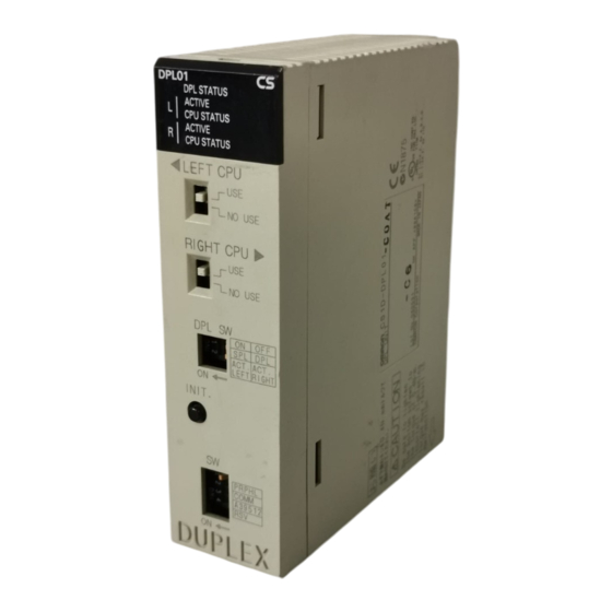
Page 81: Duplex Unit
CS1D-DPL01 (for a Duplex CPU, Single I/O Expansion System) Number mounted One Duplex Unit is required for a Duplex CPU System. Weight 200 g max. One Duplex Unit is required for a Duplex CPU System. It is not required for a Single CPU System. -
Page 82: Nomenclature
To turn OFF the power to the Duplex Unit NO USE while it is mounted, set this switch to NO USE. Duplex Unit Switches !Caution Before touching the Duplex Unit, be sure to first touch grounded metal to dis- charge static electricity. CPU Operating Switches LEFT CPU... -
Page 83: Notes
Note: Switching is disabled dur- ing operation. This switch is also disabled in a Simplex System. Note Duplex Mode and Simplex Mode can also be determined by the status of bit 08 of word A328. (2) Active Setting Switch (ACT. RIGHT/ACT. LEFT) - Page 84 PRPHL COMM A39512 In place of pins 4, 5, and 6 of the DIP switches on the right and left CPU Units, set the PRPHL and COMM pins and bit A39512 as shown in the following table. Turn OFF pins 4, 5, and 6 on both the right and left CPU Units.
- Page 85 38,400 bps, and then 115,200 bps. If the Programming Device is in a mode other than peripheral bus, or if it is set by peripheral bus to a baud rate oth- er than those that are automatically detected, the auto-detection function will not work.
-
Page 86: Ver
Memory Cards, or for front-panel DIP switch settings. Operation will continue in Duplex Mode even if these do not match for the ac- tive and standby CPU Units. The System is operating Either operation is normal in Simplex Mode, or normally in Simplex Mode. - Page 87 The left CPU Unit is active The left CPU Unit is the active (i.e., controlling) (ON) (ACT). CPU Unit. The left CPU Unit is on Either the left CPU Unit is on standby or the standby (STB). CPU Unit has stopped. Green CPU STATUS Green The left CPU Unit is in RUN The left CPU Unit is operating (i.e., in RUN or...
- Page 88 Green (ON) Green (ON) Green (ON) CPU STATUS Green (flashing) Green (ON) Green (ON) R (Non-active) ACTIVE CPU STATUS Green (flashing) Green (ON) Note The items set in bold text in the table are the main ones to indicate the status.
-
Page 89: External Dimensions
CPU error. 2. This indicator will light green if a duplex error occurs during operation. 3. The items set in bold text in the table are the main ones to indicate the sta- tus. Indicator Status when... -
Page 90: Cpu Units
Models Number of I/O Programming Data Memory Model Weight points (Number (DM + EM) of Expansion Racks) CPU Units for Duplex CPU 5,120 points 250 Ksteps 448 Kwords CS1D-CPU67H 350 g max. Systems (7 Racks) 60 Ksteps 128 Kwords CS1D-CPU65H... -
Page 91: Components
Easy backup (verification with Memory Card) with pin 7 OFF and pin 8 OFF. Pin 8: Always OFF. Note In a Duplex CPU System, the DIP switch on the front panel of the active CPU Unit is enabled (and the one on the standby CPU Unit is disabled). The DIP switch settings on the active and standby CPU Units do not necessarily have to match. - Page 92 BKUP Yellow User program and Parameter Area data is being backed up to flash memory in the CPU Unit or being restored from flash memory. Do not turn OFF the power supply to the PLC while this indicator is lit.
-
Page 93: Dip Switch Settings
Memory Card is not being accessed. DIP Switch Settings A Duplex CPU System, the DIP switch on the front panel of the active CPU Unit is enabled (and the one on the standby CPU Unit is disabled). The DIP switch settings on the active and standby CPU Units do not necessarily have to match. - Page 94 DIP switch during operation. Note 1. When pin 1 is set to ON, writing is prohibited for the user program and all parameter data (PLC Setup, I/O table registration, etc.). Moreover, it is not possible to clear the user program or parameters even by executing a memory clear operation from a Programming Device.
-
Page 95: Cpu Unit Memory Map
Units after simple backup is performed. Therefore, after the data has been read to the CPU Unit, turn the power OFF and back ON and then press the Initial Switch on the Duplex Unit. If DIP switch pin 7 on the active CPU Unit is ON, a duplex verification error will occur. - Page 96 1. The Parameter Area stores system information for the CPU Unit, such as the PLC Setup. 2. Part of the EM (Extended Data Memory) Area can be converted to file memory to handle data files and program files in RAM memory format, which has the same format as Memory Cards.
-
Page 97: Battery Compartment And Peripheral Port Covers
CPU Units 2-4-4 Battery Compartment and Peripheral Port Covers Opening the Battery Insert a small flat-blade screwdriver into the opening at the bottom of the bat- Compartment Cover tery compartment cover and lift open the cover. Insert a small flat-blade... -
Page 98: File Memory
(Backplane) 22.3 File Memory For CS1D CPU Units, the Memory Card and a specified part of the EM Area can be used to store files. All user programs, the I/O Memory Area, and the Parameter Area can be stored as files. -
Page 99: File Memory Functions In Duplex Cpu Systems
Memory Card functions can be executed in duplex only when the doing so is System enabled in the PLC Setup. In Duplex Mode, the same data that is written to the Memory Card mounted in the active CPU Unit will also be written to the Memory Card in the standby CPU Unit. -
Page 100: Parameter File
Using EM File Memory Operation in a Duplex CPU When a file is written to the EM file memory in the active CPU Unit in a Duplex System System, the same file is simultaneously written to the EM file memory in the standby CPU Unit. -
Page 101: Initializing File Memory
Device (excluding Program- ming Console). Note To delete all of the contents of a Memory Card, or to format the Memory Card, use either a CX-Programmer or Programming Console with the CPU Unit. Do not use a personal computer for this purpose. -
Page 102: Using File Memory
1. Install the Memory Card into the CPU Unit. 2. Initialize the Memory Card if necessary. 3. Name the file containing the data in the CPU Unit and save the contents in the Memory Card. 4. Read the file that is saved in the Memory Card to the CPU Unit. - Page 103 PLC Setup. 2. Initialize the EM file memory using a Programming Device. 3. Name the data in the CPU Unit and save in the EM file memory using the Programming Device. 4. Read the EM file memory files to the CPU Unit using the Programming De-...
-
Page 104: Memory Card Dimensions
Between CPU Unit and EM file memory 1,2,3... 1. Convert the part of the EM Area specified by the first bank number into file memory in the PLC Setup. 2. Initialize the EM file memory using a Programming Device. 3. Using the FWRIT(701) instruction, name the specified area in I/O memory with a file name and save in the EM file memory. - Page 105 Section 2-5 File Memory 1,2,3... 1. Pull the top end of the Memory Card cover forward and remove from the Unit. 2. Insert the Memory Card with the label facing to the right. (Insert with the on the Memory Card label and the on the CPU Unit facing each other.)
- Page 106 Section 2-5 File Memory 2. Press the Memory Card eject button after the BUSY indicator is no longer lit. BUSY indicator BUSY Memory Card eject button 3. The Memory Card will eject from the compartment. 4. Remove the Memory Card cover when a Memory Card is not being used.
-
Page 107: Programming Devices
Programming Devices Section 2-6 Note When a Memory Card is inserted into a computer using a Memory Card Adapter, it can be used as a standard storage device, like a floppy disk or hard disk. Programming Devices 2-6-1 Overview There are two types of Programming Devices that can be used: the Hand-held Programming Consoles or the CX-Programmer, which is operated on a Win- dows computer. - Page 108 EM_/EXT Sheet.) CS1W-CN114 (cable length: 0.05 m) Cable included with CQM1-PRO01-E Programming Console CQM1-PRO01 Connect the CPU Unit to the Programming Console with the following cables. CS1W-CN114 (Cable length: 0.05 m) C200H-PRO27-E Programming Console PRO27 PROGRAMMING CONSOLE OGRAMMING CONSOLE OPEN...
- Page 109 Section 2-6 Programming Devices CX-Programmer There are differences in functions depending on the version of CX-Program- mer connected to the CS1D PLC. These are listed in the following table. Duplex CPU Single CPU Remarks Programmer Systems Systems Version 2.@ or...
- Page 110 RS-232C Cable CS1W-CN118 2. If cables with model numbers ending in -V instead of -CV are used to con- nect the computer running the CX-Programmer to the RS-232C port (in- cluding when using a CS1W-CN118 Cable), a peripheral bus connection cannot be used.
- Page 111 XW2Z-500S-V 5 m Boards/Units D-Sub, 9- (See note.) pin, female Note Serial Communications Boards are supported only for Single CPU Systems. Connection Method for USB-Serial Conversion Cable Computer CS1W-CIF31 Cable 1 Cable 2 CS1W-N226/626 CS/CJ-series Peripheral Port Programming...
- Page 112 Connector hood Protection earth Note Do not use the 5-V power from pin 6 of the RS-232C port for anything but an NT-AL001 Link Adapter, CJ1W-CIF11 Conversion Adapter, or NV3W-M@20L Programmable Terminal. Using this power supply for any other external device...
- Page 113 232C Port on the CPU Unit when converting between RS-232C and RS- 422A/485 for 1:N connections. 2. Refer to Recommended Wiring Methods under Appendix F Connecting to the RS-232C Port on the CPU Unit when making your own RS-232C ca- ble. The following connections are in peripheral bus serial communications mode.
- Page 114 Protocol Host Link, NT Link, 1:N, No-protocol, or peripheral bus Note Baud rates for the RS-232C are specified only up to 19.2 kbps. The CS Series supports serial communications from 38.4 kbps to 115.2 kbps, but some com- puters cannot support these speeds. Lower the baud rate if necessary.
-
Page 115: Precautions When Connecting Programming Devices To Duplex Cpu Systems
CPU Unit to become the standby CPU Unit. For that reason, if the CX-Programmer is to be left connected, or if it is prefer- able to not have to reconnect the cable to the other CPU Unit when a switch- ing error occurs, it is recommended that the following connection be used. - Page 116 Hirakawa Hewtech Corp. b) The CJ1W-CIF11 does not provide isolation. The total length of the transmission path must therefore be 50 m or less. If the trans- mission distance is greater than 50 m, use the NT-AL001, which provides isolation, and do not include the CJ1W-CIF11 in the transmission path.
- Page 117 CPU Unit. For that reason, it is recommended that the following connection be used. For this, it is required that the Standby CPU Unit RS-232C Port Setting in the PLC Setup be set so that independent communications are disabled (i.e., the default setting).
-
Page 118: Power Supply Units
CS1D Power Supply Units. Therefore the load per CS1D Power Supply Unit is approximately 50%. If there is a breakdown at one of the CS1D Power Supply Units, operation is continued by using only the other one. In that event, the load at the one remaining CS1D Power Supply Unit will increase to 100%. -
Page 119: Cs1D Power Supply Unit Models
Always remove the metal jumper before applying a voltage of 200 to 240 V AC. Not doing so will damage the Unit. AC Input Either a power supply of 100 to 120 V AC (50/60 Hz) or 200 to 240 V AC (50/60 Hz) can be selected. Voltage Selector Before applying a voltage of 100 to 120 V AC, close the circuit using the metal jumper. -
Page 120: Dimensions
RUN Output An internal contact turns ON when the CPU Unit is operating in RUN or MON- ITOR mode. Any of the RUN outputs at the CPU Rack, an Expansion Rack, or a Long-distance Rack can be used. When Power Supply Units are used in duplex operation, the RUN output turns ON for both Power Supply Units together. -
Page 121: Backplanes
For connecting CS1D Expansion Racks. C200H Expansion I/O Racks and CS-series Expansion Racks cannot be connected. Note Backplanes produced from July 2005 have screw holes that allow an Expan- sion Rack Cable Mounting Bracket to be attached to secure the cable. - Page 122 CPU Unit for Single CPU Systems connectors Note To protect unused connectors, always cover them with CV500-COV01 I/O Unit Connector Covers (sold separately) or mount the CS1W-SP001 Spacer Unit (sold separately). When using only one Power Supply Unit, cover the unused Power Supply Unit connector with a C500-COV01 Power Supply Unit Connec- tor Covers (sold separately).
-
Page 123: Expansion Backplanes For Online Replacement
CPU Backplane for Single CPU Systems: CS1D-BC082S 505.1 6.25 17.1 26.8 2-8-2 Expansion Backplanes for Online Replacement These Backplanes are used for CS1D Expansion Racks and CS1D Long-dis- tance Expansion Racks. Model Number of slots Model Application Weight 7 or 8... - Page 124 Section 2-8 Backplanes CPU Backplane for Duplex CPU, Single I/O Expansion Systems or Single CPU Systems: CS1D-BI092 Backplane mounting screws Slots for mounting Units Mount the Backplane with four M4 screws. The Backplane is constructed so that it can be insulated from the control panel when installed.
-
Page 125: Units For Duplex Cpu, Dual I/O Expansion Systems
Section 2-9 Units for Duplex CPU, Dual I/O Expansion Systems CPU Backplane for Duplex CPU, Single I/O Expansion Systems or Single CPU Systems: CS1D-BI092 17.1 6.25 26.8 505.1 Units for Duplex CPU, Dual I/O Expansion Systems CS1D I/O Control Units and CS1D I/O Interface Units are required to con- struct a Duplex CPU, Dual I/O Expansion System. -
Page 126: Duplex Connecting Cables
34.5 Connecting the Units Mount the CS1D I/O Control Unit in either slot 0 or slot 1 (or mount two Units in both slots) of the CS1D-BC042D CPU Backplane. If CS1D I/O Control Units are mounted in slot 0 and slot 1, the Connecting Cables can be duplexed. -
Page 127: Cs1D-Ii102D I/O Interface Unit
CPU Bus Unit can be mounted. Cable connects to next Rack. If a CS1D I/O Control Unit is mounted in slot 1 only, a Basic I/O Unit, Special I/O Unit, or CPU Bus Unit cannot used in slot 0. If mounted here, a CS-series Basic I/O Unit, Special I/O Unit, or CPU Bus Unit will not operate. -
Page 128: Led Indicators
34.5 Connecting the Units Mount the CS1D I/O Interface Unit in either slot 0 or slot 1 (or mount Units in both slots) of the CS1D-BI082D Expansion Backplane. If CS1D I/O Interface Units are mounted in slot 0 and slot 1, the Connecting Cables can be duplexed. - Page 129 Incorrect Separate Expansion Backplanes cannot be connected. If a CS1D I/O Interface Unit is mounted in slot 0 only, a Basic I/O Unit, Special I/O Unit, or CPU Bus Unit can be used in slot 1. Single Connecting Cable connects to previous Rack.
-
Page 130: Units On Cs1D Long-Distance Expansion Racks
I/O Control Units and I/O Interface Units are required when creating CS1D Long-distance Expansion Racks. Terminators (CV500-TER01) are connected to the last CS1D Long-distance Expansion Rack in each series. (Up to two series of CS1D Long-distance Expansion Racks can be connected.) - Page 131 Connect the Backplane connector to the I/O expansion connector. IC102 TER ERR LEFT CPU RIGHT CPU Connect to I/O CPU Rack DPL SW cable connector. INIT. DUPLEX DUPLEX Series A Series B Note An I/O Control Unit cannot be mounted on an Expansion Backplane.
-
Page 132: Cs1W-Ii102 I/O Interface Units
Section 2-10 Units on CS1D Long-distance Expansion Racks 2-10-2 CS1W-II102 I/O Interface Units Mount a CS1W-II102 I/O Interface Unit to the leftmost slot on each Long-dis- tance Expansion Rack. Always use a CS1D-BI092 Expansion Backplane (for online replacement). Part Names and Functions... - Page 133 Connect the I/O Interface Unit to the input I/O cable connector on the Back- plane (left side). Always connect a Terminator (CV500-TER01) to the connec- tor for the next Rack when it is not used (i.e., on the last Long-distance Expansion Rack in the series).
-
Page 134: Basic I/O Units
Note 1. C200H I/O Units cannot be used. 2. An Interrupt Input Unit can be used to input interrupts for a Single CPU System. With a Duplex CPU System, however, interrupt inputs cannot be used, i.e., the Interrupt Input Unit will function only as a standard Input Unit. - Page 135 16-point Units CS1W-OD212 CS1W-INT01 with ERR indica- ER R 0 1 2 3 4 5 6 7 0 1 2 3 4 5 6 7 CS1W-IDP01 tor (load short-cir- 8 9 10 11 12 13 14 15 8 9 10 11 12 13 14 15...
-
Page 136: Interrupt Input Units
Basic I/O Units 2-11-2 Interrupt Input Units An Interrupt Input Unit can be used to input interrupts for a Single CPU Sys- tem. With a Duplex CPU System, however, interrupt inputs cannot be used, i.e., the Interrupt Input Unit will function only as a standard 16-point Input Unit. -
Page 137: Cs-Series Basic I/O Units With Connectors (32-, 64-, And 96-Pt Units)
ON time CS1W-IDP01 0.1 ms min. Dimensions The High-speed Input Unit has the same dimensions as the Units with a 20- terminal block. 2-11-4 CS-series Basic I/O Units with Connectors (32-, 64-, and 96-pt Units) CS-series Basic I/O Units are classified as Basic I/O Units. - Page 138 F (fuse burnt out) indicator Available on Output Units. 0 1 2 3 4 5 6 7 Lights when one or more fuses in the Unit blows. 8 9 10 11 12 13 14 15 Lights when external power is OFF.
- Page 139 CS1W-ID231 CS1W-OD231 CS1W-OD232 Units with Two 40-pin connectors (b) CS1W-ID261 CS1W-OD261 CS1W-OD262 CS1W-MD261 CS1W-MD262 Units with 56-pin connectors (c) CS1W-ID291 CS1W-OD291 CS1W-OD292 CS1W-MD291 CS1W-MD292 Using Soldered or Crimped Connector Approx. 169 for 32- and 64-pt Units/Approx. 179 for 96-pt Units...
-
Page 140: Unit Current Consumption
Power Supply Unit mounted), taking into account the load when an error occurs at one of the Power Supply Units. If two different kinds of Power Supply Units are to be used, calculate the current consumption using the output of the smaller-capacity Power Supply Unit. -
Page 141: Total Current And Power Consumption Calculation Example
Note 1. When duplexing by combining the CS1D-PA207R and CS1D-PD024, de- sign the total current consumption for all Units on the Rack to be within the power supply capacity of the CS1D-PD024. 2. When duplexing by combining the CS1D-PA207R and CS1D-PD025, de- sign the total current consumption for all Units on the Rack to be within the power supply capacity for the CS1D-PA027R. -
Page 142: Current Consumption Tables
Section 2-12 Unit Current Consumption 2-12-3 Current Consumption Tables Note For the current consumption of Units not shown in these tables, refer to the individual user manuals for those Units. 5-V Voltage Group Name Model Current consumption (A) CPU Backplane for Single CPU Systems CS1D-BC082S 0.17 CPU Backplane for Duplex CPU, Dual I/O CS1D-BC042D 1.2... - Page 143 CS1W-PDC01 0.15 Isolated Control Output Unit CS1W-PMV01 0.15 (Analog Output Unit) Power Transducer Input Unit CS1W-PTR01 0.15 DC Input Unit (100 mV) CS1W-PTR02 0.15 Isolated Pulse Input Unit CS1W-PPS01 0.20 Motion Control Units CS1W-MC221(-V1) 0.6 (0.80 when connected to a Teaching Box) CS1W-MC421(-V1) 0.7 (1.00 when connected...
-
Page 144: Cpu Bus Unit Setting Area Capacity
The CPU Bus Units are allocated the required number of words for settings from this area. There is a limit to the capacity of the CPU Bus Unit Setting Area of 10,752 bytes (10 Kbytes). The system must be designed so that the number of words... -
Page 145: I/O Table Settings
Section 2-14 I/O Table Settings used in the CPU Bus Unit Setting Area by all of the CPU Bus Units and the Inner Board does not exceed this capacity. If the wrong combination of Units is used, the capacity will be exceeded and either Units will operate from default settings only or will not operate at all. -
Page 146: Basic I/O Units
64-point I/O Unit Unit CS1W-MD291/292 96-point I/O Unit Note 1. An I/O setting error will occur if Units are not set correctly. 2. An I/O verification error will occur if the number of input or output words is set incorrectly. -
Page 147: Cs-Series Special I/O Units
High-speed Counter Unit CS1W-CT021/041 Other Special I/O Units GPIB Interface Unit CS1W-GPI01 Other Special I/O Units Note A Special I/O setting error will occur if Units, the number of input, or the num- ber of output words is set incorrectly. -
Page 148: Cs-Series Cpu Bus Units
PROFIBUS-DP Master Unit CS1W-PRM21 PROFIBUS Master Unit Loop Control Unit CS1W-LC001 Loop Control Unit High-resolution Motion Con- CS1W-MCH71 High Function Numerical trol Unit Control Unit Open Network Controllers ITNC-EIS/EIX-CST ONC/CS1 Bus IF ITBC-CST01 Note Supported from CS-Programmer version 4.0 or higher. -
Page 149: Duplex Functions
3-1-1 Duplex CPU Systems ........ -
Page 150: Duplex Cpu Units
Memory Cards, make sure that the contents and the capacities are the same for both of the Memory Cards. If the free space or the contents are different, write processing to the Memory Cards may not be completely correctly. - Page 151 • The setting at the Active Setting Switch on the Duplex Unit determines which of the two CPU Units is to be active. • The R and L ACTIVE indicators on the Duplex Unit show which of the two CPU Units is active. The active/standby status can also be checked using A32809 in the Auxiliary Area.
- Page 152 IOWR(223) (INTELLIGENT I/O WRITE), PID(190) (PID), RXD(235) (RECEIVE), FREAD(700) (READ DATA FILE), and FWRIT(701) (WRITE DATA FILE). The following table shows the processing related to duplex operation. For details, refer to SECTION 9 CPU Unit Operation and the Cycle Time. Processing Duplex-related processing Startup processing Duplex status is checked (i.e., whether the Unit status is active...
-
Page 153: Errors Causing Operation To Switch To The Standby Cpu Unit
The mode does not change between Duplex Mode and Simplex Mode as a result of Power Supply Unit errors. Note CS1D Power Supply Units must be used. Duplex Optical Controller Link Units or Ethernet Units can be used in a duplex config- Communications uration. Units The mode does not change between Duplex Mode and Simplex Mode as a result of Communications Unit errors. - Page 154 CPU Unit online replacement function. Note 1. To determine the cause of a switch to the standby CPU Unit, refer to A023 in the Auxiliary Area or to Mode Switch Reference, below. 2. In Simplex Mode, or in a Simplex System, operation stops when any of the above errors occur.
-
Page 155: Duplex Errors
A02608 to A02615: Year (00 to 99) The above Auxiliary Area words are cleared when the mode is restored from Simplex Mode to Duplex Mode. At that time, the contents of A023 are transferred to A019, and the contents of A024 to A026 are transferred to A020 to A022, as an error log. -
Page 156: Automatic Recovery To Duplex Operation By Self-Diagnosis
1. In order for automatic recovery to be enabled, the power to the other CPU Unit must not be OFF and the Mode Setting Switch must be set to DPL. If the mode cannot be automatically returned to Duplex Mode, the following bits in the Auxiliary Area (CPU Unit Duplex Unit Recovery Flags) will turn Right CPU Unit: A32814 turns ON. -
Page 157: Duplex Initialization
Duplex CPU Units Section 3-1 reason the standby CPU Unit previously failed (i.e., the reason for switch- ing to Simplex Operation) or the time the switch was made, use A019 (rea- sons for switching) and A020 to A022 (time of switching). 3-1-5... -
Page 158: Duplex Cpu Units With Different Unit Versions
Duplex CPU Unit operation is not possible if the unit version of the active CPU Unit Operation Is Not Unit is earlier than that of the standby CPU Unit and the Active CPU Unit uses functions not supported by the Standby CPU Unit. If this happens, a Duplex Possible Verification Error will occur and operation will be in Simplex Mode. -
Page 159: Duplex Cpu System Restrictions
The CX-Programmer will not update the unit version following online replace- ment of a Unit, and thus any data transfers will be performed as if the previous unit version was still valid even if the unit version has been changed in the online replacement procedure. - Page 160 MTIMX(554), TIMW(813), TIMWX(816), TMHW(815), TMHWX(817): (10 ms + cycle time) Note If the mode is changed from Duplex Mode to Simplex Mode during execution of a timer instruction, the accuracy in the first cycle following the mode switch is less than normal (as shown below).
- Page 161 LIGENT I/O WRITE), PID(190) (PID), RXD(235) (RECEIVE), FREAD(700) (READ DATA FILE), and FWRIT(701) (WRITE DATA FILE) • If the active and standby CPU Units cannot be synchronized when any of the above instructions are executed (except for PID), the ER Flag will turn ON.
- Page 162 1. When a duplex verification error or duplex bus error occurs when the power is turned ON, the CPU Unit goes into “CPU standby” status. 2. The cause of the “CPU standby” is stored in A322 in the Auxiliary Area. Conditions for Mode Switching in a Duplex System (Reference)
-
Page 163: Duplex Power Supply Units
Backplane's power supply of 5 V DC and 26 V DC is provided in parallel from the two Power Supply Units. Even if the power is interrupted at one of the Power Supply Units, or if one of the Power Supply Units breaks down, power can still be provided to the Rack by the other Power Supply Unit alone. -
Page 164: Primary And Secondary Communications
Communications Unit, the other as the secondary Communications Unit. The same unit number and node address are set for both of the Units, but two unit numbers (twice the amount of memory) are allocated. The primary Communications Unit performs communications with the nodes on the primary network while confirming node participation in the primary net- work. - Page 165 CS1D CPU Units for Duplex CPU Systems with a unit version of 1.1 or later or a CS1D CPU Unit for Single CPU Systems with a unit version of 2.0 or later is required to use Duplex Communication Units using primary/secondary com- munications.
-
Page 166: Duplex Connecting Cables
Units for information on the settings that are required. Duplex Connecting Cables In a CS1D Duplex CPU, Dual I/O Expansion System, it is possible to duplex the Connecting Cables between the CPU Rack and Expansion Rack and the Connecting Cables between Expansion Racks. The system components... - Page 167 Section 3-4 Duplex Connecting Cables Unit CPU Rack The system will stop if there are problems in both Connecting Cables. Expansion Rack Units Expansion Rack...
- Page 168 Section 3-4 Duplex Connecting Cables...
-
Page 169: Operating Procedures
Basic Procedures ........ -
Page 170: Introduction
• Set the DPL USE/NO USE switch to USE (CS1D-DPL02D only). • Set the communications switch on the Duplex Unit. b) Set the DIP switches and rotary switches on the front of the CPU Unit and other Units. Refer to SECTION 2 Specifications, Nomenclature, and Functions for de- tails. - Page 171 Refer to SECTION 6 PLC Setup for details. 7. Registering the I/O Tables Check the Units to verify that they are installed in the right slots. With the PLC in PROGRAM mode, register the I/O tables from the Programming Device (CX-Programmer or Programming Console). (Another method is to create the I/O tables in CX-Programmer and transfer them to the CPU Unit.)
-
Page 172: Basic Procedures
1. Connect the power supply and I/O wiring. 2. Connect communications lines if required. !Caution When 200 to 240 V AC power is being supplied, be sure to remove the jumper bar that shorts the voltage selector terminals. The Power Supply Unit will be... - Page 173 Note For simplex operation, set the mode switch to SPL. b) Set the active-CPU Unit switch to ACT.RIGHT or ACT.LEFT depending on which CPU Unit is to be used as the active CPU Unit. DPL SW ON: The left-side CPU Unit will be active.
- Page 174 Confirm that both CPU Units are the same model. Settings for Single CPU The DIP switch on the front of the CPU Unit must be set, along with other set- Systems tings. Be particularly careful when setting the peripheral port and RS-232C port settings.
- Page 175 CPU Unit. 5. Checking Initial Operation !Caution When 200 to 240 V AC power is being supplied, be sure to remove the jumper bar that shorts the voltage selector terminals. The Power Supply Unit will be damaged if 200 to 240 V AC is supplied with the jumper bar connected.
- Page 176 Single CPU Systems Not supported CS1D-S 2. Edit the PLC Setup and transfer it to the CPU Unit. (It can be transferred separately or the CXP project can be saved and the PLC Setup can be transferred together with the program.) Note In a Duplex CPU System, transfer to PLC Setup to the active CPU Unit.
- Page 177 Note Supported for CPU Unit Ver. 1.1 or later. 7. Registering the I/O Tables in the CPU Unit Registering the I/O tables allocates I/O memory to the Units actually installed in the PLC. This operation is required in CS-series PLCs.
- Page 178 Basic Procedures Section 4-2 Note The I/O tables, user program, and PLC Setup data in CS1D CPU Units is backed up in the built-in flash memory. The BKUP indicator will light on the front of the CPU Unit when the backup operation is in progress. Do not turn OFF the power supply to the CPU Unit when the BKUP indicator is lit.
- Page 179 CPU Unit. The I/O tables will automatically be copied to the standby CPU Unit as well. Note The first word allocated to each Rack can be set in the PLC Setup under the Options menu. Using a Programming Console Use the following procedure to register the I/O table with a Programming Con- sole.
- Page 180 D32000 to D32099 (100 words 1 Board) After writing the initial settings to the DM Area, be sure to restart the Units by turning the PLC OFF and then ON again or turning ON the Restart Bits for the affected Units.
- Page 181 Operating mode changed IOM Hold Bit Status at Startup When the IOM Hold Bit has been turned ON and the PLC Setup is set to pro- tect the status of the IOM Hold Bit at startup (PLC Setup address 80 bit 15...
- Page 182 PLC turned ON. Output OFF Bit (A50015) Turning ON the Output OFF Bit causes all outputs on Basic I/O Units and Special I/O Units to be turned OFF. The outputs will be turned OFF regardless of the PLC’s operating mode.
- Page 183 When a Programming Console is being used, monitor the bits with Bit/Word Monitor or 3-word Monitor. Press the SHIFT+SET Keys to force-set a bit or press the SHIFT+RESET Keys to force-reset a bit. The forced status can be cleared by pressing the NOT Key.
- Page 184 Basic Procedures Online Editing When a few lines of the program in the CPU Unit have to be modified, they can be edited online with the PLC in MONITOR mode or PROGRAM mode. When more extensive modifications are needed, upload the program from the CPU Unit to the host computer, make the necessary changes, and transfer the edited program back to the CPU Unit.
-
Page 185: Installation And Wiring
Mounting Height........ -
Page 186: Fail-Safe Circuits
Note When a fatal error occurs, all outputs from Output Units will be turned OFF even if the IOM Hold Bit has been turned ON to protect the contents of I/O memory. (When the IOM Hold Bit is ON, the outputs will retain their previous status after the PLC has been switched from RUN/MONITOR mode to PRO- GRAM mode.) -
Page 187: Installation
PLC RUN output Surge suppressor Note Do not latch the RUN output and use it in a circuit to stop a controlled object. Chattering of the relay contacts used in the output may cause incorrect opera- tion. Interlock Circuits... - Page 188 • To ensure safe access for operation and maintenance, separate the PLC as much as possible from high-voltage equipment and moving machinery. • The PLC will be easiest to install and operate if it is mounted at a height of about 1.0 to 1.6 m.
- Page 189 • Ground the mounting plate between the PLC and the mounting surface. • When I/O Connecting Cables are 10 m or longer, connect the control pan- els in which Racks are mounted with heavier power wires (3 wires at least 2 mm in cross-sectional area).
-
Page 190: Installation In A Control Panel
Note If the CS1D-PA207R Power Supply Unit is to be used at an ambient tempera- ture of 50 C or higher, provide a minimum space of 80 mm between the top of the Unit and any other objects, e.g., ceiling, wiring ducts, structural supports, devices, etc. - Page 191 • Whenever possible, route I/O wiring through wiring ducts or raceways. Install the duct so that it is easy to fish wire from the I/O Units through the duct. It is handy to have the duct at the same height as the Racks.
-
Page 192: Mounting Height
5-2-3 Mounting Height The mounting height of CPU Racks and Expansion Racks is 123 to 153 mm, depending on I/O Units mounted. If Programming Devices or connecting cables are attached, the additional dimensions must be taken into account. -
Page 193: Backplane Mounting Dimensions
1,2,3... 1. Mount the Unit to the Backplane by hooking the top of the Unit into the slot on the Backplane and rotating the I/O Unit downwards. 2. Make sure that the connector on the back of the Unit is properly inserted into the connector in the Backplane. -
Page 194: I/O Connecting Cables
20 mm min. Duct Phillips screwdriver 4. To remove a Unit, use a phillips-head screwdriver to loosen the screw at the bottom of the Unit, rotate the Unit upward, and remove it. 5-2-6 I/O Connecting Cables I/O Connecting Cables are used to connect the CPU Rack and Expansion Racks. - Page 195 • When connecting Expansion Racks with Long-distance Expansion Rack I/O Connecting Cables, install the Racks and select I/O Connecting Cables so that the total length of all I/O Connecting Cables in one system does not exceed 50 m. Example 1: CS-series I/O Connecting Cables...
- Page 196 2. A maximum of seven Long-distance Expansion Racks can be connected (including all Racks in both series). 3. Each series of Long-distance Expansion Racks must be 50 m max. with a total of 100 m max. for both series. 4. Expansion Racks and Long-distance Expansion Racks cannot be con- nected at the same time.
- Page 197 The connecting port for each CS-series I/O Connecting Cable depends on the system configuration and the Rack being connected, as shown in the follow- ing diagrams. The PLC will not operate properly if the Racks are not con- nected as shown in the following diagrams.
- Page 198 2. Always turn OFF the power supply to the PLC before connecting Cables. 3. An I/O bus error will occur and the PLC will stop if an I/O Connecting Ca- ble’s connector separates from the Rack. Be sure that the connectors are...
-
Page 199: Inner Board Installation
Long-distance Expansion Rack and a 63-mm hole will be required for Cables connecting other Racks. 5. I/O Connecting Cables cannot be cut or rejoined. Be sure to use I/O Con- necting Cables of the proper length, particularly when wiring inside panels or wiring ducts. - Page 200 CPU Unit to malfunction, damage internal components, or cause com- munications errors. 3. Before installing the Inner Board, be sure to first touch a grounded metallic object, such as a metal water pipe, in order to discharge any static build- up from your body.
-
Page 201: Power Supply Wiring
Provide an emergency stop circuit to control the power supply to the con- trolled system so that power is supplied to the controlled system only when the PLC is operating and the RUN output is ON. Connect an external relay to the RUN output from the Power Supply Unit. - Page 202 2A RESISTIVE 2A RESISTIVE Note 1. Wire the Power Supply Units so that they can be replaced safely and with- out interrupt the power supply to other Racks or devices in the event that a Power Supply Unit fails. 2. Branching wiring at a Power Supply Unit terminal block will create a dan- gerous situation if a Unit must be replaced.
-
Page 203: Wiring Methods
INCORRECT! (Unit will be damaged.) Note If 100 to 120 V AC power is supplied but the jumper bar has been removed to select 200 to 220 V AC, the Unit will not operate because the power supply voltage will be below the 85% minimum level. - Page 204 120 V AC supply voltage. For 200 to 240 V AC leave them open. !Caution The Power Supply Unit will be damaged if 200 to 240 V AC power is supplied and the voltage selector terminals are connected with the jumper bar.
- Page 205 16 to 14) V2-M3(RAV2-3.5) Round terminal with sleeve Note 1. Use crimp terminals for wiring. 2. Do not connect bare stranded wires directly to terminals. 7 mm max. 20 mm max. M3.5 self-raising terminals Torque to 0.8 N m...
- Page 206 This label prevents wire strands and other foreign matter from entering the Unit during wiring procedures. Do not forget to remove the label from the top of the Unit after wiring the Unit. The label will block air circu- lation needed for cooling.
- Page 207 Supply power to all of the Power Supply Units from the same source. 4. Do not forget to remove the label from the top of the Unit after wiring the Unit. The label will block air circulation needed for cooling.
- Page 208 To prevent noise from entering on the GR (ground) terminal as a result of a difference in potential, wire the system as shown below. • Connect all of the GR terminals on the Racks and ground them at one point only to 100 or less.
- Page 209 Wiring Communications Lines When using communications from one or more Rack in the system, ground the entire system so that only one point is grounded. (Refer to user documen- tation for the devices connected.) For detailed connection methods, refer to the Operation Manual for the Communications Unit.
-
Page 210: Wiring Cs-Series Basic I/O Units With Terminal Blocks
The following wire gauges are recommended. Wire Size AWG 22 (0.32 mm Note The current capacity of electric wire depends on factors such as the ambient temperature and insulation thickness as well as the gauge of the conductor. Wiring Terminal screws M3.5 self-rising screws... - Page 211 • In addition, make sure that the I/O indicators are not covered by the wir- ing. • Do not place the wiring for I/O Units in the same duct or raceway as power lines. Inductive noise can cause errors in operation.
-
Page 212: Wiring Cs-Series Basic I/O Units With Connectors
The I/O Units are equipped with removable terminal blocks. The lead wires do not have to be removed from the terminal block to remove it from an I/O Unit. The terminal block can be removed by taking out the terminal block mounting screws. -
Page 213: Wiring Procedure
1. Check that each Unit is installed securely. Note Do not apply excessive force on the cables. 2. Do not remove the protective label from the top of the Unit until wiring has been completed. This label prevents wire strands and other foreign matter from entering the Unit during wiring. - Page 214 Wire (0.2 to 0.13 mm Note Double-check to make sure that the Output Unit’s power supply leads haven’t been reversed. If the leads are reversed, the Unit’s internal fuse will blow and the Unit will not operate. 4. Assemble the connector (included or purchased separately) as shown in the following diagram.
- Page 215 After wiring Remove label after wiring. Connector lock screws Tighten the connector-attaching screws to a torque of 0.2 N m. The following examples show applications for preassembled OMRON Cables. Contact your OMRON dealer for more details. Connecting to a Terminal Two sets of the following Cables and Conversion Units are required.
- Page 216 CS1W-ID291 (96 input points) CS1W-OD291 (96 output points) CS1W-OD291 (96 output points) CS1W-OD292 (96 output points) CS1W-OD292 (96 output points) CS1W-MD291 (48 inputs, 48 outputs) CS1W-MD291 (48 inputs, 48 outputs) CS1W-MD292 (48 inputs, 48 outputs) CS1W-MD292 (48 inputs, 48 outputs) XW2Z-@@@H-3 Connecting...
-
Page 217: Connecting I/O Devices
Section 5-4 Wiring Methods Connecting to a Relay Two sets of the following Cables and Relay Terminals are required. Terminal CS1 Basic I/O Unit CS1 Basic I/O Unit CS1W-ID231 CS1W-ID291 (96 input points) CS1W-ID261 CS1W-OD291 (96 output points) CS1W-MD261 (inputs) - Page 218 Sensor Power Supply Output AC/DC Input Unit 7 mA • Voltage current output Output DC Input Unit Sensor Power Supply The circuit below should NOT be used for I/O devices having a voltage output. Sensor Power Supply DC Input Unit Output...
- Page 219 Note When using a reed switch as the input contact for an AC Input Unit, use a switch with an allowable current of 1 A or greater. If Reed switches with smaller allowable currents are used, the contacts may fuse due to surge cur- rents.
- Page 220 : PLC input impedance 4. Precautions on Sensor Surge Current An incorrect input may occur if a sensor is turned ON after the PLC has started up to the point where inputs are possible. Determine the time re- quired for sensor operation to stabilize after the sensor is turned ON and take appropriate measures, such as inserting into the program a timer de- lay after turning ON the sensor.
-
Page 221: Reducing Electrical Noise
In-floor duct Conduits Suspended duct If the I/O wiring and power wiring must be routed in the same duct, use shielded cable and connect the shield to the GR terminal to reduce noise. Inductive Loads When an inductive load is connected to an I/O Unit, connect a surge suppres-... - Page 222 Power cables Power lines Ground to 100 or less If the I/O wiring and power cables must be placed in the same duct, they must be shielded from each other using grounded steel sheet metal. PLC power supply and general...
-
Page 223: Plc Setup
6-2-11 CPU Duplex Tab Page ........ -
Page 224: Overview Of Plc Setup
2. CS1D CPU Unit Ver. 1.1 or later and CX-Programmer version 4.0 or later only. 3. CX-Programmer version 3.1 or higher. 4. This function is supported only by Duplex CPU Units with Unit Ver. 1.2 or later and CX-Programmer version 6.1 or higher. -
Page 225: Settings Other Than Those For Duplex Systems
Startup Mode Console’s mode switch setting at startup. • You want the PLC to go into RUN mode or MONITOR mode and start oper- ating immediately after startup. • You want the operating mode to be other than PROGRAM mode when the power is turned ON. - Page 226 Set the peripheral port or the RS-232C port communications port baud rate to “high- speed NT Link.” You want the intervals for scheduled interrupts to be set in units of 1 ms Schedules Interrupt Time Units (See note.) rather than 10 ms.
-
Page 227: Specific Plc Setup Settings
PLC Setup when using a Programming Console or the Programming Console function of an NS-series Programming Terminal. The PLC Setup is stored in the Parameter Area, which can be accessed only from a Programming Device. Do not use the Programming Console addresses as operands in programming instructions. - Page 228 Console isn’t connected, startup mode will sole: be RUN mode. Programming Console’s mode switch Default: Program Execution Settings (Single CPU Systems Only) Setting to Start Program without Waiting for Specific Units/Inner Board (Single CPU Systems Only) Address in Settings Function Related New set- Programming flags and ting’s effec-...
-
Page 229: Cpu Unit Tab Page
Section 6-2 Specific PLC Setup Settings Enable Setting in Word 83 for Inner Boards (Single CPU Systems Only) Address in Settings Function Related New set- Programming flags and ting’s effec- Console words tiveness Word Bit(s) 0: Wait for Boards. To start the CPU Unit in MONITOR or PRO-... - Page 230 FAL(006) is in error log. toring for FPD(269) will be recorded in the executed error log (A100 to A199). Set it to 1 so pre- (every cycle) 1: Don’t record user- vent these errors from being recorded. defined FAL errors in error log.
- Page 231 Word Bit(s) 0 to 3 0 to C hex (0 to 12) If bit 7 (above) is set to 1, the setting here A344 (EM After initial- specifies the EM bank where file memory File Memory ization from Default: 0 begins.
-
Page 232: Timings Tab Page
(i.e., processed in the background). 1: Executed in back- ground Default: 0 Note This setting cannot be used with Duplex CPU Systems. Communications Port Number for Background Execution Address in Settings Function Related... - Page 233 Set to 1 to enable the Watch Cycle Time A40108 At the start of 1: Bits 0 to 14 Setting in bits 0 to 14. Leave this setting at 0 (Cycle Time operation for a maximum cycle time of 1 s.
-
Page 234: Siou Refresh Tab Page
(1-ms units) power interruption (approximately 10 to operation. 25 ms for AC power and 2 to 5 ms for DC Default: 00 hex (Can’t be power after the power supply voltage drops changed dur-... -
Page 235: Unit Settings Tab Page
Special I/O Units are being used and to 47 you don’t want to extend the cycle Default: 0 time or the cycle time is so short that Cyclic Refresh- 0 to 15 0: Enabled the Special I/O Unit’s internal pro-... -
Page 236: Host Link Port Tab Page
With a Duplex CPU System, these settings are valid when the COMM pin on the DIP switch on the Duplex Unit is turned OFF. With a Single CPU System, these settings are valid when the pin 5 on the DIP switch on the CPU Unit is turned OFF. - Page 237 Bit(s) 0: Default (stan- *The default settings are for 1 start bit, 7 A61902 Takes effect dard)* data bits, even parity, 2 stop bits, and a baud (RS-232C the next rate of 9,600 bps. Port Settings cycle. 1: PLC Setup (cus-...
- Page 238 Word Bit(s) 0 to 1 00: Even These settings are valid only when the com- A61902 Takes effect 01: Odd munications mode is set to host link or no- (RS-232C the next 10: None protocol. Port Settings cycle. Changing (Also can be...
- Page 239 “PLC Setup” and set the baud rate to Changing (Also can be Default: 00 hex 9,600 bps. Flag) changed with STUP (237).) NT Link Max. (Maximum Unit Number in NT Link Mode) Address in Settings Function Related New set- Programming flags and ting’s effec-...
- Page 240 With a setting of 0, the amount of data being 2 hex: CR+LF received must be specified. A setting of 1 enables the end code in bits 0 to 7 of 164. A Default: 0 hex setting of 2 enables an end code of CR+LF.
-
Page 241: Peripheral Port Tab Page
With a Duplex CPU System, these settings are valid when the PRPHL pin on the DIP switch on the Duplex Unit is turned ON. With a Single CPU System, these settings are valid when the pin 4 on the DIP switch on the CPU Unit is turned ON. - Page 242 0 to 7 00 hex: 9,600 This setting is valid only when the communi- A61901 Takes effect 01 hex: 300 cations mode is set to the Host Link mode. (Peripheral the next 02 hex: 600 Port Settings cycle. These settings are also valid only when the...
- Page 243 NT Link* Port Settings cycle. Changing (Also can be Default: 00 hex Flag) changed with STUP (237).) NT Link Max. (Maximum Unit Number in NT Link Mode) Address in Settings Function Related New set- Programming flags and ting’s effec- Console...
-
Page 244: Peripheral Service Tab Page
New set- Programming flags and ting’s effec- Console words tiveness Word Bit(s) 0: Default (stan- *The default settings are for a baud rate of A61901 Takes effect dard)* 9,600 bps (Peripheral the next 1: PLC Setup (cus- Port Settings cycle. - Page 245 Access) tion.) Note 1. This setting cannot be used with Duplex CPU Systems. The default setting will be used even if the setting is changed. 2. A PLC Setup error will occur if any non-specified value is set. Set Time to All Events (Fixed Peripheral Servicing Time)
- Page 246 Default: 00 (hex) (5 to 255 ms in 1-ms increments) (Can’t be changed dur- ing opera- tion.) Note This setting cannot be used with Duplex CPU Systems. Peripheral Service Execution Time Address in Settings Function Related New set- Programming flags and ting’s effec-...
-
Page 247: Fins Protection Tab Page (Single Cpu Systems Only)
A maximum of 32 nodes can be set. If these settings are not made (i.e., if the total number of nodes is 0), write operations will be disabled for all nodes but the local node. -
Page 248: Comms Unit Duplex Tab Page
Section 6-2 6-2-10 Comms Unit Duplex Tab Page There are two methods that can be used for duplex communications: Active- standby and primary-secondary. There are options available for both in the PLC Setup. The methods that are used depends on the Communications Units. -
Page 249: Cpu Duplex Tab Page
Commu- nications Unit is mounted. Note This setting is supported only for CS1D CPU Units Ver. 1.1 or later. CX-Pro- grammer version 4.0 or higher must be used to make the setting. 6-2-11 CPU Duplex Tab Page... - Page 250 Use this setting to reduce startup time when the power is turned ON. When an operation switching error occurs in the Active CPU Unit, the Standby CPU Unit will become the Active CPU Unit and start operating. Address in...
- Page 251 Memory Cards. Note Data read from the Memory Card mounted in the active CPU Unit is used by both the active and standby CPU Units. Note Memory Card duplex operation can be selected with CX-Programmer Ver. 3.1 or higher.
- Page 252 1 to 63 Normally, the default setting for 4,906 words Default: 00 is used. Note If either the Transfer Program or Transfer EM option is selected the specified division size will be transferred each cycle. Transfer Program Address in...
- Page 253 Area Boards. operation 1: Do not transfer Default: 0 Note As of October 2006, there are no Inner Boards to which this setting applies. Use the default setting. Transfer Variable Area of Inner Board Address in Settings Function...
- Page 254 Device. Default: 0000 Note 1. This setting can be used only in Duplex CPU Units with Unit Ver. 1.2 and later. 2. This setting can be selected with CX-Programmer version 6.1 or higher. Enabling Unit Removal/Addition of Units without a Programming Device...
-
Page 255: Other Settings
PLC (CPU Unit) will not stop operating even if a Basic I/O Unit, Special I/O Unit, or CPU Bus Unit fails. If there are any Units that will adversely affect the system if an I/O bus error occurs, do not enable the Unit Removal without a Programming Device or Removal/Addi- tion of Units without a Programming Device function in the PLC Setup. - Page 256 Section 6-2 Specific PLC Setup Settings...
-
Page 257: I/O Allocations
Creating I/O Tables........ -
Page 258: I/O Allocations
I/O tables containing the models and locations of all Units and the allocations made to each must be created and these I/O tables must be registered in the CPU Unit. When the power supply is turned ON, the I/O tables are compared against the mounted Units to verify their accuracy. -
Page 259: Creating I/O Tables
Units that are mounted. • Create the I/O tables offline without basing them directly on the mounted Units and then transfer the I/O tables to the PLC. This is done offline on the CX-Programmer. - Page 260 When I/O memory is allocated automatically, words are automatically allo- cated to Units in the order they are mounted to the Racks. Words are allo- cated to Units from left to right starting on Rack 0 and then left to right on each Rack through Rack 7.
- Page 261 CPU Unit. Standby CPU Unit Active CPU Unit I/O Table Creation with CX-Programmer Use the following procedure to create the I/O tables offline with the CX-Pro- grammer and then transfer them to the CPU Unit. Once the Units that are to...
- Page 262 The first word for slot 00 on the Rack is set. Words Rack 1 are then allocated in order to Units from left to right. Note The first words for Racks cannot be set at the same time as the first words for slots. Setting the First Word for a Slot The first word allocated to the Unit in any slot on any Rack can be set regard- less of the order of the Rack or the position of the slot.
- Page 263 A word is set for slot 02 on the CPU Rack for group 01. Rack 0 Rack 1 A word is set for slot 02 on Rack 1 for group 02. Note The first words for Racks cannot be set at the same time as the first words for slots. Overview Method...
-
Page 264: I/O Allocation Methods
CIO 0000 and each Unit is allocated as many words as it requires. Note 1. Units that have 1 to 16 I/O points are allocated 16 bits (1 word) and Units that have 17 to 32 I/O points are allocated 32 bits (2 words). - Page 265 I/O allocation to Basic I/O Units continues from the CPU Rack to the Expan- sion Rack connected to the CPU Rack. Words are allocated from left to right and each Unit is allocated as many words as it requires, just like Units in the CPU Rack.
- Page 266 The CPU Rack is rack 0, the CS-series Expansion Rack (if there is one) is Rack 1. Rack numbers are then assigned in order to the Racks in series A of CS-series Long-distance Expansion Racks and finally to the Racks in series B of CS- series Long-distance Expansion Racks, to a maximum rack number of 7.
- Page 267 Dummy item from under the Basic I/O Unit with the correct number of I/O points. • CX-Programmer Ver. 6.0 or Later Right-click the slot for which a word is to be reserved and select Add Unit (alternatively, double-click the empty slot).
- Page 268 I/O Allocation Methods Section 7-2 The following Select Unit Dialog Box will be displayed. Click the expansion button (+) to the left of Basic I/O, select one of the Dummy Units (CS_Dummy_016/032/048/064/096/128), and click the OK Button. Note Do not execute the I/O table creation operation after completing the above...
-
Page 269: I/O Allocations To Special I/O Units
(CIO 2000 to CIO 2959) according the unit number set on the Unit. Special I/O Units can be mounted to the CPU Rack, CS-series Expansion Racks (see note). Note Refer to 2-14 I/O Table Settings for more details on the available Special I/O Units. Word Allocation The following table shows which words in the Special I/O Unit Area are allo- cated to each Unit according to unit number. -
Page 270: Allocating First Words To Racks
CIO 0100; the next Rack, words starting with CIO 0200; etc. This can make it easier to check word allocations to Units without calculating all the way from the CPU Rack. Note The first words for Racks cannot be set at the same time as the first words for slots. - Page 271 Example: Setting the First Words for Racks In this example, the first words have been set for Racks 0 (the CPU Rack), 2, and 3. For simplicity, only 16-bit Units have been used.
- Page 272 1. Press the FUN, SHIFT, and CH Keys to start the I/O table creation opera- tion. If the first work for a Rack has been set, a message saying so will ap- pear on the second line of the display.
-
Page 273: Allocating First Words To Slots (Single Cpu Systems Only)
Word Allocations When setting first words for slots, the first word must be set for slot 00 on the CPU Rack. The first word can then be set for any slot on any Rack for up to 63 other slots. -
Page 274: Setting First Slot Words
Rack 4 CIO 0600 Note Group 00 must start at slot 00 on the CPU Rack. Any word can be set. Any slot can be set on any Rack for groups 01 to 63. Setting First Slot Words from the CX-Programmer First slot words can be set from the CX-Programmer. - Page 275 Section 7-4 2. Select the Slot Start Addresses Settings Option and click the OK Button. 3. In the dialog box that will appear, set the first word for slot 00 on the CPU Rack. 4. To change the setting from CIO 0000, click the Edit Button. The follow di- alog box will appear.
-
Page 276: Detailed Information On I/O Table Creation Errors
Units mounted to the PLC. If there are any duplications, and error will occur and it will be no longer possible to edit the I/O tables. If this happens, the I/O tables will have to be deleted and recreated or retransferred from a Programming Devices. -
Page 277: Data Exchange With Cpu Bus Units
The 100 words allocated to each Unit are transferred from the DM Area to the Unit when the PLC is turned on or the Unit is restarted. Some C200H Special I/O Units do not use any of the allocated DM words and others use only a part of the allocated words. -
Page 278: Disabling Special I/O Unit Cyclic Refreshing
Ten words are allocated to each Special I/O Unit in the Special I/O Unit Area (CIO 2000 to CIO 2959) based on the unit number set on the front of each Unit. The data in the Special I/O Unit Area is refreshed in the CPU Unit every cycle during I/O refreshing (just after execution of the END(001) instruction). -
Page 279: Cpu Bus Units
CIO Area words allocated to the CPU Bus Unit of a specified unit number. Transfer of Words Allocated in the DM Area Each CPU Bus Unit is allocated 100 words in the DM Area in the range of D30000 to D31599 (100 words 16 Units). There are three times that data may be transferred through the words allocated to each Unit. -
Page 280: Fins Commands
Section 7-6 Some models transfer data in both directions, from the DM Area to the Unit and from the Unit to the DM Area. See the Unit’s Operation Manual for details on data transfers. These 100 words are generally used to hold initial settings for the CPU Bus Unit. -
Page 281: Online Addition Of Units And Backplanes
Both Units and Expansion Racks can be added during oper- ation. Note A Duplex CPU Unit with unit version 1.3 or later is required to add Units online. CPU Bus Units cannot be added online. Expansion Racks can be added online only in a Duplex CPU, Dual I/O Expansion System. - Page 282 Special I/O Units that are already mounted. Add the new Unit to a slot position so that the allocated words will not be duplicated. There are no other restrictions on the slot position.
-
Page 283: Online Addition Procedure
The starting Rack word can also be set. Special I/O Units can also be added. Maximum Number of Additional Units Only 1 Unit can be added at a time. When multiple Units are being added, add the Units one at a time. 7-7-2 Online Addition Procedure Units and Backplanes can be added online only from the CX-Programmer’s... - Page 284 Online Addition of Units and Backplanes Section 7-7 Select start. 5. Right-click the Rack/slot in which the Unit will be added and select Add Unit from the pop-up menu. The Select Unit Window will be displayed. Select the Unit to add.
- Page 285 Unit is secure. 2. Turn ON the power supply to the Rack that was added. 3. Follow steps 2 to 6 in the above Online Addition of Units procedure to use the CX-Programmer to add the Unit.
-
Page 286: Cycle Time Extension During Online Addition
Online Addition of Units and Backplanes Section 7-7 7-7-3 Cycle Time Extension during Online Addition The following table shows how much longer the cycle time will be during online addition of an Expansion Rack. Operation Cycle time extension Remarks Cycle time extension due to online... -
Page 287: Memory Areas
8-22-2 Registered I/O Tables ........ -
Page 288: Introduction
Section 8-1 Introduction Introduction The CPU Unit’s memory (RAM with battery back-up) can be divided into three parts: the User Program Memory, I/O Memory Area, and Parameter Area. This section describes the I/O Memory Area and Parameter Area. I/O Memory Area This region of memory contains the data areas which can be accessed by instruction operands. -
Page 289: Ok Ok Ok Ok Ok
Section 8-2 I/O Memory Areas I/O Memory Areas 8-2-1 I/O Memory Area Structure The following table shows the basic structure of the I/O Memory Area. Area Size Range Exter- Word Access Change Status at Forcing nal I/O access access from... -
Page 290: Overview Of The Data Areas
1. The I/O Area can be expanded to CIO 0000 to CIO 0999 by changing the first words allocated to Racks. 2. If the IOM Hold Bit (A50012) is ON, the content of these words will be held even if the operating mode is changed. - Page 291 CIO 6143 Note 1. It is possible to use CIO 0320 to CIO 0999 for I/O words by making the ap- propriate settings for the first words on the Racks. Settings for the first words on the Racks can be made using the CX-Programmer to set the first Rack addresses in the I/O table.
- Page 292 I/O Memory Areas Link Area Words in the Link Area are used for data links when LR is set as the data link area for automatic allocation for Controller Link Networks. It is also used for PLC Links. Words in the Link Area can be used in the program when LR is not set as the data link area for Controller Link Networks and PLC Links are not used.
- Page 293 The Auxiliary Area contains flags and control bits used to monitor and control PLC operation. This area is divided into two parts: A000 to A447 are read- only and A448 to A959 can be read or written. Refer to 8-11 Auxiliary Area for details on the Auxiliary Area.
- Page 294 These flags are read as bits. A Completion Flag is turned ON by the system when the corresponding timer times out (the set time elapses). Timer PVs The PVs are read and written as words (16 bits). The PVs count up or down as the timer operates. Counter Area There are two counter data areas, the Counter Completion Flags and the Counter Present Values (PVs).
-
Page 295: Data Area Properties
These flags are read as bits. A Completion Flag is turned ON by the system when the corresponding counter counts out (the set value is reached). Counter PVs The PVs are read and written as words (16 bits). The PVs count up or down as the counter operates. Condition Flags... -
Page 296: I/O Area
1. Mode changed from PROGRAM to RUN/MONITOR or vice-versa. 2. The PLC Setup’s “IOM Hold Bit Status at Startup” setting determines whether the IOM Hold Bit’s status is held or cleared when the PLC is turned I/O Area I/O Area addresses range from CIO 0000 to CIO 0319 (CIO bits 000000 to... - Page 297 Input Bits A bit in the I/O Area is called an input bit when it is allocated to an Input Unit. Input bits reflect the ON/OFF status of devices such as push-button switches, limit switches, and photoelectric switches. There are two ways for the status of input points to be refreshed in the PLC: normal I/O refreshing and IORF(097) refreshing.
- Page 298 Only) operand is an input bit or word, the word containing the bit or the word itself will be refreshed just before the instruction is executed. This immediate refreshing is performed in addition to the normal I/O refreshing performed once each cycle.
- Page 299 Limitations on Input bits There is no limit on the number of times that input bits can be used as nor- mally open and normally closed conditions in the program and the addresses can be programmed in any order.
-
Page 300: Output Bits
The default value for input response times is 8 ms and the setting range is 0 to 32 ms. Note If the time is set to 0 ms, there will still be an ON delay time of 20 s max. and an OFF delay time of 300 s due to delays caused by internal elements. - Page 301 The following IORF(097) instruction refreshes the status of all I/O points in I/O Area words CIO 0000 to CIO 0003. The status of input points is read from the Input Units and the status of output bits is written to the Output Units.
-
Page 302: Cs-Series Devicenet Area
00000 An output bit can be used in only one Output instruction that controls its sta- tus. If an output bit is used in two or more Output instructions, only the last instruction will be effective. CIO 000000 is controlled by CIO 000010. -
Page 303: Data Link Area
1. The operating mode is changed between PROGRAM and RUN or MONI- TOR mode and the IOM Hold Bit is OFF. 2. The PLC’s power supply is cycled and the IOM Hold Bit is OFF or not pro- tected in the PLC Setup. -
Page 304: Cpu Bus Unit Area
Refer to the Controller Link Units Operation Manual (W309) for more details. Words in the Link Area can be used in the program when LR is not set as the data link area for automatic allocation for Controller Link Networks and PLC Links are not used. - Page 305 1. The operating mode is changed from PROGRAM to RUN or MONITOR mode or vice-versa and the IOM Hold Bit is OFF. 2. The PLC’s power supply is cycled and the IOM Hold Bit is OFF or not pro- tected in the PLC Setup.
-
Page 306: Inner Board Area
1. The operating mode is changed from PROGRAM mode to RUN/MONITOR mode or vice-versa and the IOM Hold Bit is OFF. 2. The PLC’s power supply is cycled and the IOM Hold Bit is OFF or not pro- tected in the PLC Setup. -
Page 307: Special I/O Unit Area
Special I/O Unit Area Section 8-8 If the IOM Hold BIt (A50012) is ON and the PLC Setup’s “IOM Hold Bit Status at Startup” setting is set to protect the IOM Hold Bit, the contents of the Inner Board Area won’t be cleared when the PLC’s power supply is cycled. -
Page 308: Work Area
1. The operating mode is changed from PROGRAM mode to RUN/MONITOR mode or vice-versa and the IOM Hold Bit is OFF. 2. The PLC’s power supply is cycled and the IOM Hold Bit is OFF or not pro- tected in the PLC Setup. -
Page 309: Holding Area
H511 (bits H00000 to H51115). These words can be used only in the pro- gram. Holding Area bits can be used in any order in the program and can be used as normally open or normally closed conditions as often as necessary. -
Page 310: Auxiliary Area
Input Unit Reset input There are no restrictions in the order of using bit address or in the number of N.C. or N.O. conditions that can be programmed. 8-11 Auxiliary Area The Auxiliary Area contains 960 words with addresses ranging from A000 to A959). - Page 311 The following programming can be used with the flags in A023 to detect when the system switches from duplex to simplex operation. <> Duplex error A023 If the contents of A023 is not 0, the “duplex error” output is turned ON to indi- cate that the system has switched to simplex operation.
- Page 312 CPU Unit Setting Switch Flag A01903 ON: Changing the CPU Unit’s switch from USE to NO USE Read-only caused the previous switch from duplex to simplex opera- tion.
- Page 313 This occurs when one of the following is detected: The active CPU Unit is not mounted, the CPU Unit switch is set to NO USE, or pin 7 on the DIP switch is set for simple backup operation. User Program Verification...
- Page 314 CPU Rack, Expansion Rack, or Long- distance Expansion Rack. Error Power Supply Unit A31900 to When an error in a Power Supply Unit results in an error in the Read-only Location A31915 5-V/26-V output, one of the following bits will turn ON to show the location of the Power Supply Unit with the error.
- Page 315 Read-only ognition Error Flags A43415 number does not exist, i.e., it is not mounted, the Unit does not support duplex operation, or the unit number is illegal. Bits 00 to 15 correspond to unit numbers 0 to F. Duplex Communications Veri-...
- Page 316 When an error occurs in the active Communications Unit and operation is switched to the standby Communications Unit, an error code will be stored to show the cause of the error in the active Communications Unit. An error code is not stored when an error occurs in the standby Communications Unit.
- Page 317 (Duplex CPU Systems only) 1: Duplex Mode 0: Simplex Mode A32808 is turned OFF in duplex initialization and thus can- not be used alone to detect errors causing a switch to Sim- plex Mode. Use A32808 together with A43915 as shown below. A32808...
- Page 318 Description Access Online Replacement Flag A03115 ON: A Basic I/O Unit, Special I/O Unit, or CPU Bus Unit is Read-only being replaced online on the CPU Rack, an Expansion Rack, or a Long-distance Expansion Rack. (See note 3.) I/O Table Creation Error Flag...
- Page 319 Read/write during Unit removal without a Programming Device. When this bit is ON, a Basic I/O Unit error, Special I/O Unit error, or CPU Bus Unit error will not occur when a Unit is removed. In addition, the CPU Unit will not detect an error...
- Page 320 Replacement Completed Bit is ON, the PLC (CPU Unit) may stop operat- ing. 3. The flags in A034 to A041 indicate removal of a Unit with any one of the following functions. • Online Unit Replacement using a Programming Device •...
- Page 321 A52000 to A52007: Month (01 to 12) A52008 to A52015: Year (00 to 99) Note: If an error occurs in operation, the time of the error will be stored. If the operating mode is then changed to PRO- GRAM mode, the time that PROGRAM mode was entered will be stored.
- Page 322 The following words and bits provide file memory status for Single CPU Sys- tems or for the active CPU Unit in a Duplex CPU Systems. For a Only the Memory Card in the active CPU Unit is accessed. For information on the CPU Unit’s file memory-related status, refer to Read-only Words in Appendix B...
- Page 323 A34111 ON when an attempt is made to read a file that doesn’t exist Read-only or an attempt is made to write to a file in a directory that doesn’t exist in the left CPU Unit. File Memory Operation Flag...
- Page 324 A34211 ON when an attempt is made to read a file that doesn’t exist Read-only or an attempt is made to write to a file in a directory that doesn’t exist in the right CPU Unit. File Memory Operation Flag...
- Page 325 File names are stored in the following order: A654 to A657 (i.e., from the lowest word to the highest), and from the high- est byte to the lowest. If a file name is less than eight charac- ters, the lowest remaining bytes and the highest remaining word will be filled with spaces (20 hex).
- Page 326 These flags correspond to slots 0 to 8 on Racks 0 to 7 in Read-only A08915 order from slot 0 on Rack 0 to slot 8 on Rack 7. A flag will be ON when the fuse is burnt out in a Basic I/O Unit mounted in the corresponding slot.
- Page 327 Note: If the cycle time exceeds 2,000.0 ms, then 4E20 hex will be stored. Note With a Single CPU System, this would be the same as the instruction execu- tion cycle if Parallel Processing Mode is being used. Task Information...
- Page 328 (A52700 to A52707 must be set to 5A.) ■ Output Control Name Address Description Access Output OFF Bit A50015 Turn this bit ON to turn OFF all outputs from Basic I/O Units, Read/write Output Units, and Special I/O Units. ■ Differentiate Monitor Name Address Description Access...
- Page 329 Instruction Processing Error A29508 This flag and the Error Flag (ER) will be turned ON when an Read-only Flag instruction processing error has occurred and the PLC Setup has been set to stop operation for an instruction error.
- Page 330 Error Flag from the Memory Card to the CPU Unit at startup, including when a file is missing or a Memory Card is not mounted. The error can be cleared by turning OFF the power. (This error cannot be cleared while the power is ON.)
- Page 331 (Non-fatal error) PLC Setup Error Location A406 When there is a setting error in the PLC Setup, the location Read-only of that error is written to A406 in 4-digit hexadecimal. The location is given as the address set on the Programming Console.
- Page 332 The Duplication Error Flag (A40113) and the corresponding Read-only cation Flags A41015 flag in A410 will be turned ON when a CPU Bus Unit’s unit number has been duplicated. Bits 00 to 15 correspond to unit numbers 0 to F. CPU Bus Unit Error, Unit...
- Page 333 CPU Units only) Left-side Inner Board Error A32407 ON when an Inner Board Error has occurred in the Inner Read-only Flag (Non-fatal error) (Pro- Board in the CPU Unit on the left. A40208 will also turn ON. cess-control CPU Units only)
- Page 334 Clock Information Name Address Description Access Clock Data The clock data from the clock built into the CPU Unit is stored here in BCD. Read-only A35100 to Seconds: 00 to 59 (BCD) Read-only A35107 A35108 to Minutes: 00 to 59 (BCD)
- Page 335 Address Description Access User Program Date A090 to These words contain in BCD the date and time that the user Read-only A093 program was last overwritten. A09000 to A09007: Seconds (00 to 59) A09008 to A09015: Minutes (00 to 59)
- Page 336 Flags A20207 PMCR) or background processing (see note) can be exe- cuted with the corresponding port number. Bits 00 to 07 cor- respond to communications ports 0 to 7. When the simple backup operation is used to performed a write or compare operation for a Memory Card on a CS1D...
- Page 337 Flags ing flag is turned ON for just one cycle. Bits 00 to 07 correspond to ports 0 to 7. The cause of the error can be determined with the Commu- nications Port Completion Codes stored in A203 to A210.
- Page 338 The corresponding bit will be ON when the peripheral port is Read-only cations Flags A39407 communicating with a PT in NT link mode. Bits 0 to 7 corre- spond to units 0 to 7. Peripheral Port PT Priority A39408 to...
- Page 339 15, Ports 1 to 4 Settings A63504 port are being changed. Change Bits (Bits 1 to 4 in A620 to A635 correspond to ports 1 to 4 in Communications Units 0 to 15.) Communications Board Ports A63601 to The corresponding flag will be ON when the settings for that...
-
Page 340: Tr (Temporary Relay) Area
It is not necessary to consider TR bits when displaying ladder diagrams on the CX-Programmer. The TR bits can be used as many times as required and in any order required as long as the same TR bit is not used twice in the same instruction block. -
Page 341: Timer Area
Section 8-13 Timer Area Note A TR bit is not required when there are no execution conditions after the branch point or there is an execution condition only in the last line of the instruction block. 000001 Instruction Operand 000000... - Page 342 Completion Flag will be cleared when power is cycled. 2. If the IOM Hold BIt (A50012) is ON and the PLC Setup’s “IOM Hold Bit Sta- tus at Startup” setting is set to protect the IOM Hold Bit, the PV and Com- pletion Flag will be retained when the PLC’s power is cycled.
-
Page 343: Counter Area
Counter Area Accuracy when Switching from Duplex to Simplex Operation The accuracy of timers may be longer in the first cycle after switching from duplex to simplex operation. The following table shows the timer accuracy in the first cycle after switching. - Page 344 Section 8-15 Data Memory (DM) Area Data in the DM Area is retained when the PLC’s power is cycled or the PLC’s operating mode is changed from PROGRAM mode to RUN/MONITOR mode or vice-versa. Although bits in the DM Area cannot be accessed directly, the status of these bits can be accessed with the BIT TEST instructions, TST(350) and TSTN(351).
- Page 345 Data Memory (DM) Area DM Area Allocation to Parts of the DM Area are allocated to Special I/O Units, CPU Bus Units, and Special Units Inner Board Inner Boards for functions such as initial Unit settings. The timing for data transfers is different for these Units, but may occur at any of the three follow- ing times.
-
Page 346: Extended Data Memory (Em) Area
CPU Units only. 8-16 Extended Data Memory (EM) Area The EM Area is divided into 13 banks (0 to C) that each contain 32,768 words. EM Area addresses range from E0_00000 to EC_32767. This data area is used for general data storage and manipulation and is accessible only by word. -
Page 347: Index Registers
When a “*” character is input before a EM address, the content of that EM word is treated as BCD and the instruction will operate on the EM word in the same bank at that BCD address. Only part of the EM bank (E00000 to E09999) can be indirectly addressed with BCD values 0000 to 9999. - Page 348 MOVR(560) or MOVRW(561). Note It is possible to specify regions outside of I/O memory and generate an Illegal Access Error when indirectly addressing memory with Index Registers. Refer to Appendix E Memory Map for details on the limits of PLC memory addresses.
- Page 349 000013 P_Off ,IR0+ SET is executed only when the input condition is ON. Thus SET is not ex- ecuted above and IR0 is not incremented. Since some operands are treated as word data and others are treated as bit data, the meaning of the data in an Index Register will differ depending on the operand in which it is used.
- Page 350 0, 1, and 2, if power is interrupted in the nth cycle during execu- tion of task 1, then the execution result for the nth cycle of task 0 and the exe- cution results for the (n 1)th cycle of tasks 1 and 2 will be held.
- Page 351 Each Index Register task is processed independently, so they do not affect each other. For example, IR0 used in Task 1 and IR0 used in Task 2 are differ- ent. Consequently, each Index Register task has 16 Index Registers.
- Page 352 Index Registers Register values from the storage words (e.g., DM area) at the beginning of each task. The values stored for each task in other areas (e.g., DM area) can then be edited using the Programming Devices, Host Link commands, or FINS commands.
-
Page 353: Data Registers
Index Registers when addressing words indirectly. The value in a Data Register can be added to the PLC memory address in an Index Register to specify the absolute memory address of a bit or word in I/O memory. -
Page 354: Task Flags
0, 1, and 2, if power is interrupted in the nth cycle during execu- tion of task 1, then the execution result for the nth cycle of task 0 and the exe- cution results for the (n 1)th cycle of tasks 1 and 2 will be held. -
Page 355: Condition Flags
Note The CX-Programmer treats condition flags as global symbols beginning with All Condition Flags are cleared when the program switches tasks, so the sta- tus of the ER and AER flags are maintained only in the task in which the error occurred. - Page 356 Turned ON when there is a carry in the result of an arithmetic opera- tion or a “1” is shifted to the Carry Flag by a Data Shift instruction. The Carry Flag is part of the result of some Data Shift and Symbol Math instructions.
- Page 357 The Condition Flags are cleared when the program switches tasks, so the sta- tus of a Condition Flag cannot be passed to another task. For example the status of a flag in task 1 cannot be read in task 2. (The flag’s status must be transferred to a bit.)
-
Page 358: Clock Pulses
Section 8-21 Clock Pulses 8-21 Clock Pulses The Clock Pulses are flags that are turned ON and OFF at regular intervals by the system. Name Label Symbol Operation 0.02 s Clock Pulse 0.02s P_0_02_s ON for 0.01 s 0.01 s OFF for 0.01 s... -
Page 359: Parameter Areas
The Registered I/O Tables are tables in the CPU Unit that contain the informa- tion on the model and slot location of all of the Units mounted to the CPU Rack and Expansion I/O Racks. The I/O Tables are written to the CPU Unit with a Programming Device operation. -
Page 360: Routing Tables
Create the Routing Tables with a Programming Device or the Controller Link Support Software and transfer the tables to each CPU Unit. The following dia- gram shows the Routing Tables used for a data transfer from PLC #1 to PLC Node number M... -
Page 361: Cpu Bus Unit Settings
Section 8-22 Parameter Areas Relay Network Table This table lists the network address and node number of the first relay node to contact in order to reach the destination network. The destination network is reached through these relay nodes. Local Network Table This table lists the network address and unit number of the Communications Unit connected to the local PLC. - Page 362 Section 8-22 Parameter Areas...
-
Page 363: Cpu Unit Operation And The Cycle Time
Operating Modes ........ - Page 364 9-5-22 Network Instructions ........
-
Page 365: Cpu Unit Operation
CPU Unit Operation 9-1-1 General Flow for Duplex CPU Systems The following flowchart shows the overall operation of the CPU Units in a Duplex CPU System. CPU Unit Operation Flow This section describes the internal operation of the CPU Unit and the cycle used to perform internal processing. -
Page 366: General Flow For Single Cpu Systems
General Flow for Single CPU Systems The following flowchart shows the overall operation of the CPU Unit. Note The CPU Unit’s processing mode is set to Normal Mode, Parallel Processing with Synchronous Memory Access, or Parallel Processing with Asynchronous Memory Access in the PLC Setup (Programming Console address 219, bits 08 to 15). - Page 367 Section 9-1 CPU Unit Operation Parallel Processing (Single CPU Systems Only) The following two types of processing are performed in parallel in either of the Parallel Processing Modes. 1,2,3... 1. Program execution: Includes user program execution and I/O refreshing. It is this cycle time that is monitored from a Programming Device.
-
Page 368: I/O Refreshing And Peripheral Servicing
This includes both events from external devices and service requests to external devices. Most peripheral servicing for CS1D PLCs involved FINS commands. The spe- cific amount of time set in the system is allocated to each type of servicing... -
Page 369: Initialization At Startup
PLC Setup. 2. In either of the Parallel Processing Modes for a Single CPU System, all pe- ripheral servicing except for file access is performed in the peripheral ser- vicing cycle. - Page 370 CPU Unit Operation Note 1. The I/O memory is held or cleared according to the status of the IOM Host Bit and the setting for IOM Hold Bit Status at Startup in the PLC Setup (read only when power is turned ON).
-
Page 371: Duplex Initialization (Duplex Cpu Systems Only)
The Duplex System is initialized when the power supply is turned ON, when operation is started, when the user program or PLC Setup is transferred, etc. It involves transferring data from the active CPU Unit to the standby CPU Unit and verifying that both CPU Units contain the same data. Duplex initialization is performed only in Duplex Mode. -
Page 372: Ok Ok Ok Ok Ok Ok
CPU Unit Operating Modes active CPU Unit will not be switched. Because of this, operation will not con- tinue if an error that would cause the CPU Unit to be switched occurs during duplex initialization, including CPU errors, memory errors, fatal Inner Board errors, program errors, exceeding the cycle time limit, and execution of FALS instructions). -
Page 373: Operating Mode Changes And I/O Memory
• Any task that has not yet been executed, will be in disabled status (INI). Executed if inter- rupt condition is • A task will go to READY status if the task is set to go to READY status at met. startup or the TASK ON (TKON) instruction has been executed for it. -
Page 374: Power Off Operation
Bit at power ON settings in the PLC Setup. 85% of the rated voltage: AC power: 85 V for a 100 V AC system and 170 V for a 200 V AC system The following processing will be performed if power drops only momentari- ly (momentary power interruption). -
Page 375: Description Of Operation
Description of Operation 1,2,3... 1. Power OFF will be detected if the 100 to 120 V AC or 200 to 240 V AC pow- er supply falls below 85% of the rated voltage for the power OFF detection time (somewhere between 10 to 25 ms). -
Page 376: Instruction Execution For Power Interruptions
Section 9-3 Power OFF Operation 2. If the Power OFF Detection Delay Time is set (0 to 10 ms in 1-ms incre- ments) in the PLC Setup, the CPU reset signal will turn ON while the inter- nal power supply is maintained and the CPU Unit will be reset. - Page 377 DI(693) and EI(694) CPU reset signal are executed. If A530 is not set to A5A5 hex, i.e., if prohibiting power interruption processing is not enabled, only the current instruction will be executed and then power interruption processing will be performed.
-
Page 378: Computing The Cycle Time
Computing the Cycle Time Computing the Cycle Time 9-4-1 CPU Unit Operation Flowchart The CS1D CPU Units process data in repeating cycles from the overseeing processing up to peripheral servicing as shown in the following diagram. Normal Processing Mode Power ON Checks Unit connection status. - Page 379 Section 9-4 Computing the Cycle Time Parallel Processing Mode Power ON Checks Unit connection status Program Execution Peripheral Cycle Servicing Cycle Check hardware, Check user program etc. memory, etc. Check OK? Check OK? Set error flags. Flashing: Non-fatal Services Execute user...
-
Page 380: Cycle Time Overview
• Fixed peripheral servicing time in the PLC Setup Note 1. The cycle time is not affected by the number of tasks that are used in the user program. The tasks that affect the cycle time are those cyclic tasks that are READY in the cycle. - Page 381 Processing time and fluctuation cause Services events for Special I/O Units. If a uniform peripheral servicing time hasn’t been set in the PLC Setup for this Note Peripheral servicing does not servicing, 4% of the previous cycle’s include I/O refreshing.
- Page 382 Program Execution Cycle The program execution cycle time depends on the following conditions. • Type and number of instructions in the user program (in all cyclic tasks that are executed during a cycle, and within interrupt tasks for which the execution conditions have been satisfied).
- Page 383 • Fixed peripheral servicing time in the PLC Setup The program execution cycle time is the total time required for the PLC to per- form the 5 operations shown in the following tables. Cycle time = (1) + (2) + (3) + (4) + (5)
- Page 384 Normal Mode. Partial peripheral servicing ((5) below), however, is restricted to servicing for file and I/O memory access. The program execution cycle time is the total time required for the PLC to per- form the 5 operations shown in the following tables.
-
Page 385: I/O Unit Refresh Times For Individual Units And Boards
1. The cycle time display on a Programming Device is the Program Execution Cycle Time. 2. The peripheral service cycle time varies with the event load and number of Units that are mounted. In a Parallel Processing Mode, however, this vari- ation will not affect the program execution cycle time. - Page 386 Note Longer I/O refresh times will be required according to the distance from the CPU Rack to the Unit when these Units are mounted to Long-distance Expan- sion Racks. Multiply the values given in the table by the factors on line *1 in the following graph.
- Page 387 CPU Rack to the Unit when these Units are mounted to Long-distance Expansion Racks. Multiply the values given in the table by the factors on line *2 in the graph on page 350 for the increases for data link words and send/ receive words.
- Page 388 Section 9-4 Computing the Cycle Time Increase in Cycle Time Caused by CPU Bus Units Unit Name Model Increase Remarks CPU Bus Units Controller Link CS1W-CLK11 0.1 ms There will be an increase of 0.1 ms Unit CS1W-CLK21-V1 + 0.7 s x number of data link With Long-dis- words.
-
Page 389: Cycle Time Calculation Example
Expansion Racks. Multiply the values given in the table by the factors on line *2 in the graph on page 350 for the increases and by the factors on line *3 for the additional increases for data link words and send/receive words. -
Page 390: Online Editing Cycle Time Extension
Note 1. When there is one task, online editing is processed all in the cycle time fol- lowing the cycle in which online editing is executed (written). When there are multiple tasks (cyclic tasks), online editing is separated, so that for n tasks, processing is executed over n to n 2 cycles max. -
Page 391: Duplex Processing Cycle Time Extension (Duplex Cpu Systems Only)
CS1D-CPU67H 20 ms + 520 ms = 540 ms Set the monitoring time (10 to 40,000 ms, default: 1 s) +B* for the cycle time high enough to allow for this increase. Also, confirm that the system will oper- ate correctly and safely even for the maximum cycle time, including the increase for duplex initialization. -
Page 392: I/O Response Time
CPU Unit) Maximum cycle Maximum cycle Time required by the CS1D to detect the long cycle time (depends on the setting of time exceeded time + 0.5 ms the maximum cycle time) plus the operation switching time (0.5 ms). -
Page 393: Interrupt Response Times (Single Cpu Systems Only)
20.0 ms Minimum I/O response time = 1.5 ms + 20 ms + 0.2 ms = 21.7 ms Maximum I/O response time = 1.5 ms + (20 ms 2) + 0.2 ms = 41.7 ms 9-4-9 Interrupt Response Times (Single CPU Systems Only) -
Page 394: Instruction Execution Times And Number Of Steps
CS1D CPU Units. The total execution time of instructions within one whole user program (i.e., within all the tasks that are executed in a cycle) is the process time for pro- gram execution when calculating the cycle time (See note.). -
Page 395: Sequence Input Instructions
(steps) column. The number of steps required in the user program area for each of the instructions varies from 1 to 7 steps, depending upon the instruc- tion and the operands used with it. The number of steps in a program is not the same as the number of instructions. -
Page 396: Sequence Output Instructions
OR BIT TEST OR TSTN 0.14 0.14 0.24 Note 1. When a double-length operand is used, add 1 to the value shown in the length column in the following table. 2. Not supported by Duplex CPU Systems. 9-5-2 Sequence Output Instructions Instruction... -
Page 397: Sequence Control Instructions
OUTPUT !OUTB (See note +21.42 +21.52 Note 1. When a double-length operand is used, add 1 to the value shown in the length column in the following table. 2. Not supported by Duplex CPU Systems. 9-5-3 Sequence Control Instructions Instruction... -
Page 398: Timer And Counter Instructions
0.12 0.12 When loop is ended Note 1. When a double-length operand is used, add 1 to the value shown in the length column in the following table. 2. Not supported by Duplex CPU Systems. 9-5-4 Timer and Counter Instructions... -
Page 399: Comparison Instructions
When resetting 1 word 4.16 ms 4.16 ms 4.16 ms When resetting 1,000 words Note When a double-length operand is used, add 1 to the value shown in the length column in the following table. 9-5-5 Comparison Instructions Instruction Mnemonic Code... -
Page 400: Data Movement Instructions
DOUBLE AREA ZCPL RANGE COM- PARE Note 1. When a double-length operand is used, add 1 to the value shown in the length column in the following table. 2. Not supported by Duplex CPU Systems. 9-5-6 Data Movement Instructions Instruction... -
Page 401: Data Shift Instructions
0.42 0.50 COUNTER PV TO REGISTER Note 1. When a double-length operand is used, add 1 to the value shown in the length column in the following table. 2. Not supported by Duplex CPU Systems. 9-5-7 Data Shift Instructions Instruction... - Page 402 0.56 SHIFT N-BITS LEFT SHIFT N-BITS NASR 0.22 0.22 0.32 RIGHT DOUBLE NSRL 0.40 0.40 0.56 SHIFT N-BITS RIGHT Note When a double-length operand is used, add 1 to the value shown in the length column in the following table.
-
Page 403: Increment/Decrement Instructions
BINARY INCREMENT DOUBLE ++BL INCREMENT DECREMENT DOUBLE DEC- REMENT BCD Note When a double-length operand is used, add 1 to the value shown in the length column in the following table. 9-5-9 Symbol Math Instructions Instruction Mnemonic Code Length Execution time ( s) - Page 404 Section 9-5 Instruction Execution Times and Number of Steps Instruction Mnemonic Code Length Execution time ( s) Conditions (steps) CPU6@H CPU6@S CPU4@S (Duplex (Single (Single CPU) CPU) CPU) DOUBLE BCD +BCL 13.8 13.8 15.0 ADD WITH CARRY SIGNED 0.18 0.18 0.20...
-
Page 405: Conversion Instructions
DIVIDE BCD DIVIDE DOUBLE BCD 17.7 17.7 18.9 DIVIDE Note When a double-length operand is used, add 1 to the value shown in the length column in the following table. 9-5-10 Conversion Instructions Instruction Mnemonic Code Length Execution time ( s) - Page 406 Section 9-5 Instruction Execution Times and Number of Steps Instruction Mnemonic Code Length Execution time ( s) Conditions (steps) CPU6@H CPU6@S CPU4@S (Duplex (Single (Single CPU) CPU) CPU) ASCII CON- Converting 1 digit VERT into ASCII 11.2 11.2 11.7 Converting 4 digits...
-
Page 407: Logic Instructions
0.32 DOUBLE COM- COML 0.40 0.40 0.56 PLEMENT Note When a double-length operand is used, add 1 to the value shown in the length column in the following table. 9-5-12 Special Math Instructions Instruction Mnemonic Code Length Execution time ( s) -
Page 408: Floating-Point Math Instructions
LD, AND, OR+>=F FLOATING- FSTR 48.5 48.5 48.9 POINT TO ASCII ASCII TO FVAL 21.1 21.1 21.3 FLOATING- POINT Note When a double-length operand is used, add 1 to the value shown in the length column in the following table. -
Page 409: Double-Precision Floating-Point Instructions
Section 9-5 Instruction Execution Times and Number of Steps 9-5-14 Double-precision Floating-point Instructions Instruction Mnemonic Code Length Execution time ( s) Conditions (steps) CPU6@H CPU6@S CPU4@S (Duplex (Single (Single CPU) CPU) CPU) DOUBLE SYM- LD, AND, OR+=D 10.3 BOL COMPARI- LD, AND, OR+<>D... -
Page 410: Table Data Processing Instructions
DOUBLE PWRD 223.9 223.9 224.2 EXPONEN- TIAL POWER Note When a double-length operand is used, add 1 to the value shown in the length column in the following table. 9-5-15 Table Data Processing Instructions Instruction Mnemonic Code Length Execution time ( s) -
Page 411: Data Control Instructions
10.6 DELETE 354.0 354.0 436.0 For 1,000-word table Note When a double-length operand is used, add 1 to the value shown in the length column in the following table. 9-5-16 Data Control Instructions Instruction Mnemonic Code Length Execution time ( s) -
Page 412: Subroutine Instructions
535.2 535.2 709.8 Autotuning when sampling Note 1. When a double-length operand is used, add 1 to the value shown in the length column in the following table. 2. Not supported by Duplex CPU Systems. 9-5-17 Subroutine Instructions Instruction Mnemonic... -
Page 413: Interrupt Control Instructions
Section 9-5 Instruction Execution Times and Number of Steps Note When a double-length operand is used, add 1 to the value shown in the length column in the following table. 9-5-18 Interrupt Control Instructions Instruction Mnemonic Code Length Execution time ( s) -
Page 414: Basic I/O Unit Instructions
527.8 (duplex) Note 1. When a double-length operand is used, add 1 to the value shown in the length column in the following table. 2. Not supported by Duplex CPU Systems. 3. Read/write times depend on the Special I/O Unit for which the instruction... -
Page 415: Serial Communications Instructions
CHANGE STUP 341.2 341.2 400.0 SERIAL PORT SETUP Note When a double-length operand is used, add 1 to the value shown in the length column in the following table. 9-5-22 Network Instructions Instruction Mnemonic Code Length Execution time ( s) -
Page 416: File Memory Instructions
Binary data plex) 73-character direc- 1,073.3 tory + file name in (duplex) binary Note When a double-length operand is used, add 1 to the value shown in the length column in the following table. 9-5-24 Display Instructions Instruction Mnemonic Code Length... -
Page 417: Debugging Instructions
Section 9-5 Instruction Execution Times and Number of Steps Note When a double-length operand is used, add 1 to the value shown in the length column in the following table. 9-5-26 Debugging Instructions Instruction Mnemonic Code Length Execution time ( s) -
Page 418: Block Programming Instructions
(See note 63.6 92.3 PERIPHERAL SERVICING Note 1. When a double-length operand is used, add 1 to the value shown in the length column in the following table. 2. Not supported by Duplex CPU Systems. 9-5-29 Block Programming Instructions Instruction Mnemonic... - Page 419 25.2 Default setting 24.9 24.9 27.8 Normal execution TIMWX 22.3 22.3 25.2 Default setting 24.9 24.9 27.8 Normal execution Note When a double-length operand is used, add 1 to the value shown in the length column in the following table.
-
Page 420: Text String Processing Instructions
LD, AND, OR+<>$ character LD, AND, OR+<$ LD, AND, OR+>$ LD, AND, OR+>=$ Note When a double-length operand is used, add 1 to the value shown in the length column in the following table. 9-5-31 Task Control Instructions Instruction Mnemonic... - Page 421 Note Duplex CPU Systems only. These functions are not supported by Duplex CPU Systems. For example, if OUT is used with an address of CIO 000000 to CIO 25515, the program capacity of the previous PLC would be 2 words per instruction and that of the CS-series PLC would be 1 (2 –...
- Page 422 Section 9-5 Instruction Execution Times and Number of Steps...
-
Page 423: Troubleshooting
10-2-7 Power Supply Check........ -
Page 424: Error Log
The number of records is stored in binary in the Error Log Pointer (A300). Note The Error Log Pointer can be reset by turning ON the Error Log Pointer Reset Bit (A50014). This operation will also clear the error log display for Program- ming Devices, but it will not clear the data in the Error Log itself (A100 to A199). -
Page 425: Error Processing
• Waiting for Inner Board (Single CPU Systems or Process-control CPU Units only) Expansion Rack power interruption Waiting for operation Waiting for operation Waiting for operation Note The cause of the CPU Unit remaining on standby is stored in A322. -
Page 426: Error Information
Lit red: CPU error causing operation to switch Flashing read: Other error causing operation to switch Not lit: PROGRAM mode or other status Note When two or more errors occur at the same time, the highest (most serious) error code will be stored in A400. - Page 427 Note 1. The status of the indicators are given in RUN or MONITOR mode. “---” in- dicates that the indicator may be any status. 2. The ACTIVE indicator on the new active CPU Unit will light. 3. The indicator will flash green for any fatal errors except an I/O bus error.
-
Page 428: Troubleshooting Flowcharts
Note *1: *** indicates the FAL or FALS number. *2: ** indicates the unit number. *3: In x-y, x indicates the rack number and y indicates left or right. *4: * indicates the unit number. *5: * indicates the rack number. - Page 429 Note *1: *** indicates the FAL or FALS number. *2: ** indicates the unit number. *3: In x-y, x indicates the rack number and y indicates left or right. *4: * indicates the unit number. *5: * indicates the rack number.
- Page 430 Note *1: *** indicates the FAL or FALS number. *2: ** indicates the unit number. *3: In x-y, x indicates the rack number and y indicates left or right. *4: * indicates the unit number. *5: * indicates the rack number.
-
Page 431: Power Interruptions
Not lit indicators CPU STATUS Flashing green For all of the following errors, operation will stop if the error occurs with a Sin- gle CPU Systems, or in either Duplex Mode or Simplex Mode with a Duplex CPU System. Error... - Page 432 FALS instruction. I/O memory will not be cleared for a FALS instruction. If the I/O Memory Hold Bit is ON, I/O memory will be held, but outputs to all Output Units will be turned OFF.
- Page 433 Units, FALS(007) will be executed at the same time in both CPU Units and operation will not switch to the standby, causing the CPU STATUS indicators on the Duplex Unit to flash red for both CPU Units. This is true for other errors causing operation to switch.
- Page 434 For all of the following errors, operation will be switched to the standby and operation will continue in a Duplex CPU System in Duplex Mode. If the error occurs in a Single CPU System or in a Duplex CPU System in Simplex Mode, operation will stop.
- Page 435 Then, clear the error. gram stopped will be stored in tion A298 and A299. The task If the error occurred in only one of the CPU where the program stopped Units, use one of the following methods. will be stored in A294.
- Page 436 Special I/O Units that don’t require frequent refreshing. If the error occurred in only one of the CPU Units, use one of the following methods. • Toggle the USE/NO USE switch for the...
- Page 437 CPU STATUS Not lit Note 1. I/O memory will be cleared when a fatal error occurs. 2. If the I/O Hold Bit is ON, I/O memory will not be cleared, but all outputs from Output Units will be turned OFF.
- Page 438 Section 10-2 Error Processing Troubleshooting Table For the following errors, operation will stop for a Duplex CPU System in Duplex Mode or in Simplex Mode, or for a Single CPU System. Error Program- Error Error Flags Probable cause Possible remedy...
- Page 439 Operation will continue for any of the following errors for a Duplex CPU Sys- tem in Duplex Mode or in Simplex Mode, or for a Single CPU System. For some of these errors, operation for a Duplex CPU System will switch from Duplex Mode to Simplex Mode and for other errors, operation will remain in Duplex Mode.
- Page 440 Mode Continues operation will continue in Duplex Mode and in RUN or MONITOR mode. Oper- ation will also continue if any of these errors occurs in Simplex Mode or in a Single CPU System. A non-fatal error has occurred if the indicators have the following conditions during operation in RUN or MONITOR mode.
- Page 441 Refer to the Unit’s operation manual Unit error CPU Bus series series CPU Bus Unit. to find and correct the cause of the Unit Error CPU Bus error. Restart the Unit by toggling its The corresponding flag in A417 is...
-
Page 442: Other Errors
10-2-5 Error Codes The following table list error in order of severity, with the most serious error given first. When more than one error occurs at the same time, the most seri- ous error code will be stored in A400. - Page 443 1. * = Rack number Note 2. *** = FAL or FALS number 3. x-y: x = Rack number, y = L for left or R for right 4. * = Unit number 5. ** = Unit number 6. These errors occur only for Duplex CPU Systems.
-
Page 444: Duplex Check
Error eliminated? Switch the switch for the CPU Unit where the error remains to NO USE. Replace the CPU Unit. Switch the switch for the new CPU Unit to USE. automatic recovery to Duplex Mode set in the PLC Setup? Press the initialization button. - Page 445 Turn the power supply OFF. CPU Unit) from Programming Device. ON or OFF? Be sure the active CPU Unit switch is set and do not use the Simple Backup Mode. Turn the power supply back ON. Check One or more ON A31707/A31710 Turn OFF the power supply.
- Page 446 Errors Duplex Power Supply Error Flag (A31602) is ON. Check the location of the Power Supply Unit by reading A319 and A320 from a Programming Console. Follow the procedure in 10-2-7 Power Supply Check and correct any problems with the power supply connection.
-
Page 447: Power Supply Check
200 to set correctly? 200 to 240 VAC: Open 240 VAC. The Power Supply Unit will be destroyed if 200 to 240 VAC is supply with the jumper connected. Is there no power supply selector? Is Power indicator lit? -
Page 448: Memory Error Check
Confirm (autotransfer at that the required files are on the startup error) Memory Card and the pin 2 on the DIP switch is OFF. The write life of the flash memory has A40310 (flash memory error) been exceeded. -
Page 449: Program Error Check
(instruction error (A294) and address (A298 and A299) that flags) ON? stopped the program. Turn the power supply OFF and then back ON again. 10-2-10 Cycle Time Overrun Error Check The cycle time was too long. Executing the program resulted in exceeding the monitor time. -
Page 450: Battery Error Check
Error Processing Section 10-2 10-2-12 Battery Error Check Battery error occurred. Set the PLC Setup so that battery errors are not detected. (DM Area contents may be unstable when this Battery-free operation setting is used.) required? Refer to the CS/CJ Programming Manual for details. -
Page 451: I/O Check
Section 10-2 Error Processing 10-2-14 I/O Check The I/O check flowchart is based on the following ladder diagram section assuming that SOL1 does not turn ON. (LS1) (LS1) 000002 000003 000500 SOL1 000500 Start Indicator of 000500 normal? Monitor ON/OFF status of... -
Page 452: Troubleshooting Racks And Units
Error occurs in units of 8 or 16 points. I/O bit turns ON. All bits in one Unit do not turn ON. Special I/O Units Refer to the Operation Manual for the Special I/O Unit to troubleshoot any other errors. Symptom Cause... - Page 453 (2) Input bit number is used for output Correct program. instruction. Input irregularly turns (1) External input voltage is low or unstable. Adjust external input voltage to within rated ON/OFF. range. (2) Malfunction due to noise. Take protective measures against noise,...
- Page 454 Adjust voltage to within rated range. (3) Terminal block screws are loose. Tighten screws. (4) Faulty terminal block connector contact. Replace terminal block connector. (5) An overcurrent (possibly caused by a Replace fuse or Unit. short at the load) resulted in a blown fuse in the Output Unit.
-
Page 455: Troubleshooting Errors In Duplex Connecting Cables
The CS1D I/O Control Unit and CS1D I/O Interface Unit LED indicators all indicate errors in the side where the break occurred. The CABLE ERR L Indi- cator is lit red in the Units above the break and the CABLE ERR R Indicator is lit red in the Units below the break. - Page 456 The CS1D I/O Control Unit and CS1D I/O Interface Unit LED indicators all indicate errors in the side where the error occurred. The CABLE ERR L Indi- cator is lit red in the Units above the error and the CABLE ERR R Indicator is lit red in the Units below the error.
- Page 457 If either cable is connected to the wrong side when the power supply is turned ON, an I/O bus error C will occur and the PLC will not operate. Note If the cable to the other slot is discon- nected, the PLC will stop.
- Page 458 Troubleshooting Errors in Duplex Connecting Cables Section 10-4...
-
Page 459: Inspection And Maintenance
11-2 Replacing User-serviceable Parts ........11-2-1 Battery Replacement........ -
Page 460: Inspections
Inspection is recommended at least once every six months to a year, but more frequent inspections will be necessary in adverse environments. Take immediate steps to correct the situation if any of the conditions in the fol- lowing table are not met. -
Page 461: Tools Required For Inspections
• Thermometer and hygrometer (humidity meter) 11-1-2 Unit Replacement Precautions Check the following when replacing any faulty Unit. • Either do not replace a Unit until the power is turned OFF or perform one of the following. Replacing a CPU Unit Set the switch on the Duplex Unit to “NO USE”... -
Page 462: Replacing User-Serviceable Parts
OFF. This data will not be stable when the power supply is turned OFF if a battery is not installed or the battery has expired its useful life. • Retained regions of I/O memory (such as the Holding Area and DM Area) - Page 463 Power-supply rate (%) Low Battery Indicators If the PLC Setup has been set to detect a low-battery error, the ERR/ALM indicator on the front of the CPU Unit will flash when the CPU Unit detects that the battery is nearly discharged.
- Page 464 BATT LOW Once a low-battery error has been detected, it will take 5 days before the bat- tery fails. Battery failure can be delayed by ensuring that the CPU Unit power is not turned OFF until the battery has been replaced.
- Page 465 ON for at least one minute before turning the power OFF again.) Note There is a capacitor in the CPU Unit that will back up memory while the bat- tery is being replaced. If this capacitor is not completely charged by turning ON the power supply for one minute, data will not be stable during battery replacement.
- Page 466 5. With the old battery connected, insert the new battery’s connector in the open connector in the CPU Unit. Be sure that the connector is inserted so that its red wire is at the top and the white wire is at the bottom. New battery...
- Page 467 Note 1. With CPU Units Ver. 1.2 or later in a Duplex CPU System, even if this pro- cedure is not used and the old battery is disconnected with the power OFF (power OFF and no battery connected), memory will be backed up for a short time by an internal capacitor.
-
Page 468: Replacing A Cpu Unit
Section 11-3 Replacing a CPU Unit !Caution Turn ON the power after replacing the battery for a CPU Unit that has been unused for a long time. Leaving the CPU Unit unused again without turning ON the power even once after the battery is replaced may result in a shorter battery life. -
Page 469: Cpu Unit Replacement Procedure
!Caution You must set the USE/NO USE switch on the Duplex Unit to NO USE before replacing a CPU Unit to turn OFF the power supply to the CPU Unit. If a CPU Unit is replaced while power is still being provided (i.e., with the switch set to USE), the CPU Backplane for Duplex CPU System or Duplex Unit may be damaged. - Page 470 Simplex Mode and operation will stop if an error occurs in the CPU Unit that is currently running. 6. Use the following procedure if the PLC Setup has not been changed to en- able automatic recovery to Duplex Mode.
-
Page 471: Online Replacement Of I/O Units, Special I/O Units, And Cpu Bus Units
Unit being replaced may result in unexpected operation of con- trolled devices or systems. !Caution If an Output Unit is replaced and ON status is held in memory for that Unit, the corresponding output will turn ON as soon as the online replacement opera- tion has been completed. - Page 472 To exit online replacement, go to step 7. To start online replacement, con- tinue to step 4. 4. Specify the number of the Rack and the slot where the Unit is to be re- placed. In this example, slot 8 on Rack 5 is used. In 5-8=I32 in the following dis- plays, 5 is the rack number, 8 is the slot number, and I32 is the Unit type.
- Page 473 Unit being replaced may result in unexpected operation of con- trolled devices or systems. !Caution If an Output Unit is replaced and ON status is held in memory for that Unit, the corresponding output will turn ON as soon as the online replacement opera- tion has been completed.
-
Page 474: Related Auxiliary Area Flags
Description A034 00 to 04 Used to confirm when online replacement is in progress for a slot on Rack 0. A bit will be ON when online replacement is in progress for the corresponding slot. Bits 00 to 04 correspond to slots 0 to 4. - Page 475 Note 1. If a Duplex Controller Link Unit is used, “a” will be added to the end of the display for the active Unit and “s” will be added for the standby Unit. For example, “NS12a” would be a Controller Link Unit with a unit number of 12 functioning as the active Unit.
-
Page 476: Replacing More Than One Unit At A Time
EXT Key and then using the following procedure. Multiple Units Replace Start ~5-8=I32 If the EXT Key is pressed in the status shown above, the display will appear to enable inputting another rack number and slot number. Replace? ?-?=... -
Page 477: Error Displays
The CLR Key can be pressed to display the Unit registered in the I/O tables and the Unit that was mounted. The display on the left is the registered Unit and the display on the right is the Unit that is currently mounted. -
Page 478: Online Replacement Precautions For Special I/O And Cpu Bus Units
ON as soon as the online replacement opera- tion has been completed. Confirm system safety in advance. !Caution If the settings in the new Unit are not the same as those in the Unit that was replaced, unexpected operation may result possibly causing an accident. - Page 479 1) Turn OFF the power supply to all external devices connected to words CS1W-AD081 the Unit before starting the replacement procedure. CS1W-AD081-V1 2) Set the same unit number on the new Unit as was set on the Unit being replaced. Analog Output Unit num- Settings in...
- Page 480 1) Turn OFF the power supply to all external devices connected to words the Unit before starting the replacement procedure. 2) Set the same unit number on the new Unit as was set on the Unit being replaced. 3) When the new Unit has been mounted and the online replace- ment operation has been completed for it, the settings stored in the CPU Unit will be automatically transferred to the new Unit.
- Page 481 Unit being replaced. Terminating Area words: 2) If a Relay Terminal Block is not being used or if the node resistance • Data link set- of the Unit being replaced is at the end of the network,...
- Page 482 1) Turn OFF the power supply to all external devices con- nected to the Unit before starting the replacement proce- dure. 2) Set the same unit number on the new Unit as was set on the Unit being replaced. 3) When the new Unit has been mounted and the online...
- Page 483 Unit is replaced and the communi- cations connector is reconnected. 6) Set the same unit number on the new Unit as was set on the Unit being replaced. Note The version 1 (-V1) DeviceNet Unit (to be released soon) will support a simple backup function.
-
Page 484: Removal/Addition Of Units
2. If just the Removal/Addition of Units without a Programming Device func- tion is set in a CPU Unit with unit version 1.2, it will not operate. An I/O bus error will occur if a Unit is removed without using a Programming Device. - Page 485 Special I/O Unit Area is retained while the Unit is removed.) 4. An I/O bus error, which can be caused by a Unit malfunction, is normally a fatal error that stops operation. When the Unit Removal without a Program-...
- Page 486 Bit) by allocating the bit to an external switch on an Input Unit and inputting the signal or turning ON the bit from a PT. (The bit can also be turned ON from the CX-Programmer or a Programming Console.) Note Do not turn ON the Maintenance Start Bit (A80015) continuously from the lad- der program or other source.
- Page 487 2 Units. 2 more Units. 1 more Unit. Note If you want to detect errors in other Units before all of the Units have been replaced online, turn OFF the Maintenance Start Bit. Online Replacement Completed Bit (A80215) When the Unit Removal without a Programming Device function is selected...
- Page 488 If the Maintenance Start Bit is turned ON by mistake, an error will not be generated even if a Unit fails. Therefore, the Maintenance Start Bit is turned OFF after a short time. (In this example, it is turned OFF by the 5-minute timer.)
- Page 489 Units without a Programming Device function is enabled in the PLC Setup. !Caution Do not touch any of the terminals or terminal blocks while the power is being supplied. Doing so may result in electric shock. Note a) If an Output Unit is being replaced, output ON status is retained and the outputs will go back ON as soon as online replacement is completed.
- Page 490 Unit without a Programming Device, turn ON the Maintenance Start Bit (A80015) before removing the Unit. When this bit is ON, the errors above will not occur when the Unit is re- moved. c) Do not turn ON the Maintenance Start Bit (A80015) continuously from the ladder program or other source.
-
Page 491: Replacing Power Supply Unit
Unit or for periodic maintenance. 1,2,3... 1. Turn OFF the power supply to the Unit to be replaced and remove the wir- ing. If the RUN output is being used in the external sequence circuits, ei- ther keep the RUN output shorted when removing the wires or prepare the sequence circuits so that they will be no adverse affects when the RUN output wires are removed. - Page 492 Replace Note Before replacing an Expansion Unit, verify that the other Expansion Unit in the Rack is operating normally by checking the Duplex Com- munications Cable Error Flags in A270 as well as the LED Indica- tors on each Expansion Unit.
-
Page 493: Replacing The Duplex Unit
!Caution Before replacing the Duplex Unit, be sure to set the Duplex Unit’s DPL Switch to NO USE. If the Unit is removed while the DPL Switch is set to USE, the CPU Backplane may fail or the PLC may operate unpredictably. - Page 494 Switch is set to NO USE. Note Once the DPL Switch is set to NO USE, the power to the Duplex Unit will remain OFF even if the DPL Switch is switched to USE un- less the Duplex Unit has been removed. If you want to restart the same Duplex Unit, remove the Duplex Unit, mount it again, and pro- ceed to step 4.
- Page 495 Section 11-7 Replacing the Duplex Unit 4. Set the Duplex Unit’s DPL Switch to USE. Verify that the ACTIVE and CPU STATUS Indicators for the active CPU Unit are both lit on the front of the Duplex Unit. Duplex Unit...
- Page 496 Section 11-7 Replacing the Duplex Unit...
-
Page 497: Specifications Of Basic I/O Units And High-Density I/O Units
Simultaneously ON 24-V DC inputs for CS1W-ID291/MD291/MD292 Note The Interrupt Input Unit can be used to input interrupts with a Single CPU System. With a Duplex CPU System, the Interrupt Input Unit will function only as a standard Input Unit. - Page 498 • I/O terminals in terminal connection diagrams are shown as viewed from the front panel of the Unit. • Terminal numbers A0 to A9 and B0 to B9 are used in this manual, but they are not printed on all Units.
- Page 499 COM1 Note 1. The Input ON and OFF response times for Basic I/O Units can be set to 0 ms, 0.5 ms, 1 ms, 2 ms, 4 ms, 8 ms, 16 ms, or 32 ms in the PLC Setup. When the response times have been set to 0 ms, the ON response time will be 10 ms maximum and the OFF response time will be 40 ms maximum due to internal element delays.
- Page 500 COM1 Note 1. The Input ON and OFF response times for Basic I/O Units can be set to 0 ms, 0.5 ms, 1 ms, 2 ms, 4 ms, 8 ms, 16 ms, or 32 ms in the PLC Setup. When the response times have been set to 0 ms, the ON response time will be 10 ms maximum and the OFF response time will be 40 ms maximum due to internal element delays.
- Page 501 0 ms due to internal element delays. 2. Terminal numbers A0 to A9 and B0 to B9 are used in this manual, but they are not printed on all Units. 3. Terminal numbers A0 to A20 and B0 to B20 are printed on all Units.
- Page 502 Polarity of the input power supply can connected in either direction. Note 1. Terminal numbers A0 to A9 and B0 to B9 are used in this manual, but they are not printed on the Unit. 2. The Interrupt Input Unit can be used to input interrupts with a Single CPU System. With a Duplex CPU...
- Page 503 • The minimum pulse width (ON time) that can be read by the High-speed Input Unit is 0.1 ms. • Input data in the internal circuits is cleared during the input refresh period. Note Terminal numbers A0 to A9 and B0 to B9 are used in this manual, but they are not printed on the Unit.
- Page 504 • Both COM0 and COM1 have two pins each. Although they are internally connected, wire all points completely. Note The ON response time will be 20 s maximum and OFF response time will be 300 s maximum even if the response times are set to 0 ms due to internal element delays.
- Page 505 • COM0, COM1, COM2, and COM3 have two pins each. Although they are internally con- nected, wire all points completely. Note The ON response time will be 120 s maximum and OFF response time will be 300 s maximum even if the response times are set to 0 ms due to internal element delays.
- Page 506 The polarity of the input power supply can be in either direction. Note 1. The Input ON and OFF response times for Basic I/O Units can be set to 0 ms, 0.5 ms, 1 ms, 2 ms, 4 ms, 8 ms, 16 ms, or 32 ms in the PLC Setup.
- Page 507 Specifications of Basic I/O Units and High-density I/O Units Appendix A Terminal Connections The polarity of the input power supply can be in either direction, as indicated by the dotted lines. COM2 COM3 COM1 COM4 COM0 COM5 Figure 1 Terminal Connections: CS1W-ID291 24-V DC 96-point Input Unit...
- Page 508 Terminal Connections COM0 2 A 250 VAC, 2 A 24 VDC, 0.1 A 120 VDC max. COM1 Note Terminal numbers A0 to A9 and B0 to B9 are used in this manual, but they are not printed on the Unit.
- Page 509 2 A 250 VAC, when a DC power supply 2 A 24 VDC, is used. 0.1 A 120 VDC max. Note Terminal numbers A0 to A9 and B0 to B9 are used in this manual, but they are not printed on the Unit.
- Page 510 COM0 Output indicator Fuse OUT8 OUT15 COM1 Fuse Terminal Connections COM0 0.5 A 250 VAC max. COM1 Note Terminal numbers A0 to A9 and B0 to B9 are used in this manual, but they are not printed on the Unit.
- Page 511 Output indicator ERR indicator OUT0 OUT7 Fuse Blown fuse detection circuit Terminal Connections 1.2 A 250 VAC max. Note Terminal numbers A0 to A9 and B0 to B9 are used in this manual, but they are not printed on the Unit.
- Page 512 • When wiring, pay careful attention to the polarity. • The load may operate incorrectly if the polarity is reversed. Note Terminal numbers A0 to A9 and B0 to B9 are used in this manual, but they are not printed on the Unit.
- Page 513 20 M between the external terminals and the GR terminal (100 V DC) Dielectric Strength 1,000 V AC between the external terminals and the GR terminal for 1 minute at a leak- age current of 10 mA max. No. of Circuits...
- Page 514 • When wiring, pay careful attention to the polarity. The load may operate if the polarity is reversed. • Although the +V and COM terminals of rows A and B of CN1 and CN2 are internally connected, wire all points completely.
- Page 515 3 CN2 circuits OUT15 Fuse The ERR indicator will light if a fuse blows or if the external power supply is turned OFF, and the corresponding Flag in the Basic I/O Unit Information Area (A050 to A089) will turn Terminal Connections Refer to Figure 2.
- Page 516 24 VDC COM2 12 to 24 VDC COM3 COM1 12 to 24 VDC 12 to 24 VDC COM4 COM0 12 to 24 VDC COM5 12 to 24 VDC Figure 2 Terminal Connections: CS1W-OD291 24-V DC 96-point Transistor Output Unit (Sinking Outputs)
- Page 517 When wiring, pay careful attention to the polarity of the external power supply. The load may operate if the polarity is reversed. Note Terminal numbers A0 to A9 and B0 to B9 are used in this manual, but they are not printed on the Unit.
- Page 518 20 M between the external terminals and the GR terminal (100 V DC) Dielectric Strength 1,000 V AC between the external terminals and the GR terminal for 1 minute at a leakage current of 10 mA max. No. of Circuits 32 (16 points/common, 2 circuits) Internal Current Consumption 5 V DC 270 mA max.
- Page 519 When the output current of any output exceeds the detection current, the output for that point will turn OFF. At the same time, the ERR indicator will light and the corresponding flag (one for each common) in the Basic I/O Unit Information Area (A050 to A089) will turn Terminal Connections I/O word "m"...
- Page 520 • When wiring, pay careful attention to the polarity of the external power supply. The load may operate if the polarity is reversed. • Although the COM(+V) and 0V of rows A and B of CN1 and CN2 are internally con- nected, wire all points completely.
- Page 521 3 CN2 circuits OUT15 The ERR indicator will light if a fuse blows or if the external power supply is turned OFF, and the corresponding Flag in the Basic I/O Unit Information Area (A050 to A089) will turn Terminal Connections When wiring, pay careful attention to the polarity of the external power supply.
- Page 522 24 VDC COM2 12 to 24 VDC COM3 COM1 12 to 24 VDC 12 to 24 VDC COM4 COM0 12 to 24 VDC COM5 12 to 24 VDC Figure 3 Terminal Connections: CS1W-OD292 24-V DC 96-point Transistor Output Unit (Sourcing Outputs)
- Page 523 20 M between the external terminals and the GR terminal (100 V DC) Dielectric Strength 1,000 V AC between the external terminals and the GR terminal for 1 minute at a leakage cur- rent of 10 mA max. Internal Current Con- 5 V DC 270 mA max.
- Page 524 0 ms due to internal element delays. 2. The input ON and OFF response times for Basic I/O Units can be set to 0 ms, 0.5 ms, 1 ms, 2 ms, 4 ms, 8 ms, 16 ms, or 32 ms in the PLC Setup.
- Page 525 IN15 1000 pF The ERR indicator will light if a fuse blows or if the external power supply is turned OFF, and the corresponding Flag in the Basic I/O Unit Information Area (A050 to A089) will turn ON. Terminal Connections Refer to Figure 4.
- Page 526 Specifications of Basic I/O Units and High-density I/O Units Note 1. The input ON and OFF response times for Basic I/O Units can be set to 0 ms, 0.5 ms, 1 ms, 2 ms, 4 ms, 8 ms, 16 ms, or 32 ms in the PLC Setup. The ON response time will be 120 s maximum and OFF response time will be 300 s maximum even if the response times are set to 0 ms due to internal element delays.
- Page 527 20 M between the external terminals and the GR terminal (100 V DC) Dielectric Strength 1,000 V AC between the external terminals and the GR terminal for 1 minute at a leakage cur- rent of 10 mA max. Internal Current Con- 5 V DC 270 mA max.
- Page 528 • Although the +V and COM terminals of rows A and B of CN1 and CN2 are internally con- nected, wire all points completely. Note The ON response time will be 120 s maximum and OFF response time will be 300 s maximum even if the response times are set to 0 ms due to internal element delays.
- Page 529 IN15 1000 pF The ERR indicator will light if a fuse blows or if the external power supply is turned OFF, and the corresponding Flag in the Basic I/O Unit Information Area (A050 to A089) will turn ON. Terminal Connections Refer to Figure 5.
- Page 530 Specifications of Basic I/O Units and High-density I/O Units Note 1. The input ON and OFF response times for Basic I/O Units can be set to 0 ms, 0.5 ms, 1 ms, 2 ms, 4 ms, 8 ms, 16 ms, or 32 ms in the PLC Setup. The ON response time will be 120 s maximum and...
- Page 531 • When wiring, pay careful attention to the polarity. The load may operate if the polarity is reversed. • Although the +V and COM terminals of rows A and B of CN1 and CN2 are internally connected, wire all points completely.
- Page 532 0 ms due to internal element delays 2. The input ON and OFF response times for Basic I/O Units can be set to 0 ms, 0.5 ms, 1 ms, 2 ms, 4 ms, 8 ms, 16 ms, or 32 ms in the PLC Setup.
- Page 533 Contact Protection Circuit Arc killers are used with the Contact Output Unit in order to prolong the life of each Relay mounted to the Con- tact Output Unit, prevent noise, and reduce the generation of carbide and nitrate deposits. Arc killers can, how- ever, reduce relay life if not use correctly.
- Page 534 Note Do not connect a capacitor as an arc killer in parallel with an inductive load as shown in the following dia- gram. This arc killer is very effective for preventing spark discharge at the moment when the circuit is opened.
- Page 535 The CS1W-OD212/OD232/OD262/MD262 turn ON an alarm output bit that corresponds to the external load output number. There is an alarm output bit for every common. When an alarm output bit turns ON, use a self-holding bit for the alarm in the user program and turn OFF the corresponding output.
-
Page 536: Programming Example
Mounted in odd slot For example, when the CS1W-OD212 is mounted in slot 0 on Rack 0, A05001 will turn ON if the output 8 is short-circuited. When the CS1W-OD262 is mounted in slot 1 of Rack 0, A05011 will turn ON if the output m+3 is short-circuited. -
Page 537: Auxiliary Area Allocations
Appendix B Auxiliary Area Allocations The tables list the functions of Auxiliary Area words and bits in order of their addresses. For a list of Auxiliary Area words and bit by function, refer to SECTION 8 Memory Areas. The Auxiliary Area consists of read-only words A000 to A447 and read/write words A448 to A959. - Page 538 Words Bits mode startup settings change A020 to Previous Cause of Switching to Simplex Operation (Duplex CPU Systems only) A022 Time of The time of the previous switch from Held Held Data from Previous duplex to simplex operation is stored.
- Page 539 OFF: Normal A024 to Current Cause of Switching to Simplex Operation (Duplex CPU Systems only) A026 (Check in new active CPU Unit after switch to simplex operation.) Time of The time operation was switched from...
- Page 540 A03508 ment Slot ON bit. being performed replace- Flags for Bits 00 to 08 correspond to slots 0 to 8 for OFF: Online ment Expan- each Expansion Slot replacement not operation sion Rack being performed...
- Page 541 Primary/Secondary Communications A04215 Units The error information of the secondary Unit when an error occurs in the second- ary Unit will be stored in the bits for unit number 2 (A0400 to A0407). A043 to A04300 Communications Units with unit numbers...
- Page 542 Words Bits mode settings change A050 A05000 Basic I/O A bit will turn ON to indicate when a ON: Fuse blown Every Unit Infor- fuse has blows. The bit numbers OFF: Normal cycle A05007 mation, correspond to the fuse number on Rack 0 the Unit.
- Page 543 PLC ming Setup. Device Enabled Flag A09914 IR/DR Turn ON this bit to share index and ON: Shared Held Cleared Operation data registers between all tasks. (default) between Turn OFF this bit to use separate...
- Page 544 20 most recent errors can be details or 0000. stored. Seconds: Each error record occupies 5 words; 00 to 59, BCD the function of these 5 words is as Minutes: follows: 00 to 59, BCD Beginning word: Hours: Error code (bits 0 to 15)
- Page 545 (The flag for a given port is turned OFF while a network instruction with that port number is being executed.) (When the simple backup operation...
- Page 546 Communi- corresponding flag is turned ON for error end, other- cations just one cycle. Bits 00 to 07 corre- wise OFF Error spond to ports 0 to 7. Flags Use the Used Communications Port Number stored in A218 to determine which flag to access.
- Page 547 When the Basic I/O Unit input I/O Unit response time setting is changed in Input re- the PLC Setup while the PLC is in sponse PROGRAM mode, the setting in the time set- PLC Setup will not match the actual...
- Page 548 A263 Time operation. The cycle time is 429,496,729.5 recorded in 8-digit hexadecimal with the leftmost 4 digits in A263 and the (0.1ms units) rightmost 4 digits in A262. With a Single CPU System in Paral- lel Processing Mode, the maximum cycle time for instruction execution will be stored.
- Page 549 (A298 and A299 contain the pro- gram address where program exe- cution was stopped.) A295 A29508 Instruc- This flag and the Error Flag (ER) will ON: Error Flag Cleared Cleared A294, tion Pro- be turned ON when an instruction...
- Page 550 A298/ Error Flag illegal access error has occurred OFF: Normal A299 and the PLC Setup has been set to stop operation an illegal access Setup error. (This error occurs when a (Opera- region of memory is access ille- tion gally.) CPU Unit operation will stop...
- Page 551 A50115 (A50100 to A50115) is turned from initialization.) OFF to ON or the power is turned OFF: Not initial- izing Bits 00 to 15 correspond to unit numbers 0 to 15. Use these flags in the program to prevent the CPU Bus Unit’s refresh...
- Page 552 Error Power Supply Unit Location When an error in a Power Supply Unit results in an error in the 5-V/26-V output, one of the following bits will turn ON to show the location of the Power Supply Unit with the error. A31602 (Duplex Power Supply Unit Error Flag) can be used to determine if there is an error and the following bits can be used to locate the error.
- Page 553 Error Power Supply Unit Location When the voltage on the primary side of the Power Supply Unit drops or is interrupted, one of the following bits will turn ON to show the location of the Power Supply Unit with the error. A31602 (Duplex Power Supply Unit Error Flag) can be used to deter- mine if there is an error and the following bits can be used to locate the error.
- Page 554 ON: Right CPU CPU Unit active CPU Unit. Unit Location OFF: Left CPU Flag Unit A32810 Duplex Indicates the system configuration, CS1H CPU Units or Held When A32811 System CS1D CPU Units. power is Configura- turned ON A32810 OFF, A32811 OFF:...
- Page 555 Words Bits mode settings change A341 File Memory Information for Left CPU Unit (Duplex CPU Systems only) A34100 Memory Indicates the type of Memory Card, 0 hex: None Held When A34300 Card Type if any, installed in the left CPU Unit.
- Page 556 Words Bits mode settings change A342 File Memory Information for Right CPU Unit (Duplex CPU Systems only) A34200 Memory Indicates the type of Memory Card, 0 hex: None Held When A34300 Card Type if any, installed in the right CPU Unit.
- Page 557 07 or or when mounted if the Memory A342 Memory Card is not formatted, or if Card there is an error in the for- turns power is mat. turned ON With Duplex CPU Systems Memory Card duplex opera- tion disabled: ON when an error occurs at the active CPU Unit.
- Page 558 A341 missing file doesn’t exist or an attempt 11 or OFF: Normal is made to write to a file in a A342 directory that doesn’t exist. turns With Duplex CPU Systems Memory Card duplex opera- tion disabled: ON when an error occurs at the active CPU Unit.
- Page 559 Note: Turns OFF when operation begins. A34315 Memory Card Detected Flag ON: Memory Held Cleared When ON when a Memory Card has been Card detected Memory detected. OFF: Memory Card is Card not mounted With Duplex CPU Systems detected...
- Page 560 Memory last bank in EM are formatted for Func- use as file memory. tion set- To convert the EM Area for use as ting and file memory, first set the PLC EM File Setup’s EM File Memory Function Memory setting to 1, set the PLC Setup’s EM...
- Page 561 A39307 Communi- cating with a PT in NT link mode. OFF: Not com- normal cations Bits 0 to 7 correspond to units 0 to 7. municating response Flag to the token A39308 RS-232C The corresponding bit will be ON for...
- Page 562 A39407 Communi- nicating with a PT in NT link mode. OFF: Not com- normal cations Bits 0 to 7 correspond to units 0 to 7. munication response Flag to the token A39408 Peripheral The corresponding bit will be ON for...
- Page 563 A298 and A299. The type of program error that occurred will be stored in bits 8 to 15 of A295. Refer to the description of A295 or to 2-3 Checking Programs of CS/CJ Series Programmable Controllers (W394) for more details on program errors.
- Page 564 The duplicated unit number is indi- cated in A409 to A416. (This flag will be turned OFF when the error is cleared.) A40114 I/O Bus ON when an error occurs in a data ON: Error Cleared Cleared A404 Error Flag...
- Page 565 A427. (This flag will be turned OFF when the error is cleared.) A40204 Battery ON if the CPU Unit’s battery is dis- ON: Error Cleared Cleared Error Flag connected or its voltage is low and...
- Page 566 CPU Task Unit. Systems) Errors This flag will also be turned ON if an setting) attempt is made to refresh a Special I/O Unit’s I/O from an interrupt task with IORF(097) while the Unit’s I/O is being refreshed by cyclic I/O refreshing (duplicate refreshing).
- Page 567 ERR/ALM indicator on the front not executed of the CPU Unit will flash. The bit in A360 to A391 that corre- sponds to the FAL number specified in FALS(006) will be turned ON and the corresponding error code will be written to A400.
- Page 568 Words Bits mode settings change A406 PLC Setup When there is a setting error in the 0000 to 01FF Cleared Cleared When A40210 Error PLC Setup, the location of that error error Location is written to A406 in 4-digit hexadec- occurs imal.
- Page 569 I/O Unit Error Flag (A40206) will be turned ON. Each bit corresponds to a unit num- ber. Bit 00 in A418 to bit 15 in A423 correspond to unit numbers 0 to 95. If the PLC Setup is set to turn ON...
- Page 570 0 to F. nized (Bits A42800 to A43315 correspond to unit numbers 00 to 5F (0 to 95).) The CPU Unit will continue operat- ing and the ERR/ALM indicator on the front of the CPU Unit will flash.
- Page 571 Held Cleared When A40214 Communi- Units Communica- communi- A31603 A43615 cations ON: An error was detected in self- tions Units cations A042 to Switched diagnosis in the active Communica- switched A049 Flags tions Unit and operation was OFF: Normal switched...
- Page 572 PLC operation begins.) Read/Write Area The following words and bits can be written by the user to control various aspect of PLC operation. Addresses Name Function Settings...
- Page 573 Held Cleared ate Moni- dition has been established during exe- condition cution of differentiation monitoring. established Com- (This flag will be cleared to 0 when dif- OFF: Not yet pleted ferentiation monitoring starts.) established Flag A50811 Trace Trig- ON when a trigger condition is estab-...
- Page 574 BCD. A51200 to A51207: Second (00 to 59) A51208 to A51215: Minute (00 to 59) A51300 to A51307: Hour (00 to 23) A51308 to A51315: Day of month (01 to (These words are not cleared at start- up.) A514...
- Page 575 OFF when the RS-232C port is restarted. (These flags are not valid in peripheral bus mode and only bit 5 is valid in NT Link mode.) Bits 0 and 1: Not used. Bit 2: ON when there was a parity error.
- Page 576 Status at Timing Related after startup Flags, Word mode Settings change A530 A53000 Power Set to A5A5 hex to disable power inter- A5A5 hex: Cleared Cleared Interrup- rupts between DI(693) and EI(694) Masking power A53015 tion Dis- instructions. interruption able processing...
- Page 577 A62002 Communi- ON: Changing Held Cleared cations It is also possible for the user to indi- OFF: Not Unit 0, cate a change in serial port settings by changing Port 2 turning these flags ON. Settings...
- Page 578 Serial Communications Board after the settings have been changed. A63602 Communi- 1: Changing Retained Cleared cations It is also possible for the user to indi- 0: Not chang- Board cate a change in serial port settings by Port 2 turning these flags ON. Settings...
- Page 579 File names are stored in the following order: A654 to A657 (i.e., from the low- est word to the highest), and from the highest byte to the lowest. If a file name is less than eight characters, the lowest remaining bytes and the highest remaining word will be filled with spaces (20 hex).
- Page 580 Communications Port Auto-allocation Instruction (Instruction) Note In CS1D PLCs, the following flags are provided in a special read-only area and can be specified with the labels given in the table. These flags are not contained in the Auxiliary Area. Flag area...
- Page 581 A198 A199 The following data would be generated in an error record if a memory error (error code 80F1) occurred on 1 April 2002 at 17:10:30 with the error located in the PLC Setup (04 hex). 8 0 F 1...
- Page 582 3. 4101 to 42FF will be stored for FAL numbers 001 to 511. 4. The contents of the error flags for a duplicate number error are as follows: Bits 0 to 7: Unit number (binary), 00 to 5F hex for Special I/O Units, 00 to 0F hex for CPU Bus Units, Bits 8 to 14: All zeros, Bit 15: Unit type, 0 for CPU Bus Units and 1 for Special I/O Units.
- Page 583 A20015: Initial Task Flag A20015 will turn ON during the first time a task is executed after it has reached executable status. It will be ON only while the task is being executed and will not turn ON if following cycles.
- Page 584 Appendix B Auxiliary Area Allocations A20110: Online Editing Wait Flag Wait Online edit processing A20110 A50100 to A50115: CPU Bus Unit Restart Bits Automatically turned OFF by system Example: Unit No. 1 A50101 (or at startup) CPU Bus Unit Restart Bit...
-
Page 585: Memory Map Of Plc Memory Addresses
Parameter Areas: These areas contain CPU Unit system setting data, such as the PLC Setup, CS-series CPU Bus Unit Setups, etc. An illegal access error will occur if an attempt is made to access any of the parameter areas from an instruction in the user program. - Page 586 Note The contents of the EM Area bank currently specified in the program is stored at these addresses. For example, if bank 8 is specified, the same contents as at 58000 to 5FFFF will be stored at F8000 to FFFFF.
-
Page 587: Plc Setup Coding Sheets For Programming Console
Appendix D PLC Setup Coding Sheets for Programming Console Use the following coding sheets when setting the PLC Setup from a Programming Console. 10@@@@ Value (hex) Rack 0, Slot 0 I/O Response Time 8 ms No filter 0.5 ms 1 ms... - Page 588 Appendix D PLC Setup Coding Sheets for Programming Console 11@@@@ Value (hex) Rack 0, Slot 2 I/O Response Time 8 ms No filter 0.5 ms 1 ms 2 ms 4 ms 8 ms 16 ms 32 ms Value (hex) Rack 0, Slot 3 I/O Response Time...
- Page 589 0001 Unit number 0 set as primary Unit. 4000 Unit number 14 set as primary Unit. Note The unit number of the secondary Unit is one higher than that of the pri- mary Unit. 96@@@@ (Duplex CPU Systems only) Value (hex)
- Page 590 Operation starts (See note 1.) Note 1. This setting is enabled when the operation during duplex initializa- tion setting is enabled. 2. Do not set this setting to any value other than those indicated above. (Duplex CPU Systems only) 127@@@@...
- Page 591 5AA5 5AA5 Enabled. 132@@@@ (Duplex CPU Systems only) Value (hex) Turning ON the Special I/O Unit or CPU Bus Unit Error Flag when Special I/O Unit or CPU Bus Unit Is Removed Any value Disabled. except AA Enabled. Value (hex)
- Page 592 1,200 bps 0004 2,400 bps 0005 4,800 bps 0006 9,600 bps 0007 19,200 bps 0008 38,400 bps 0009 57,600 bps 000A 115,200 bps Note Set 0000 to 0009 hex for standard NT Links and 000A hex for high- speed NT Links.
- Page 593 Appendix D PLC Setup Coding Sheets for Programming Console @@@@ Peripheral Port Value (hex) Host link Unit No. 0000 No. 0 0001 No. 1 0002 No. 2 001F No. 31 150@@@@ Peripheral Port Value (hex) NT Link Mode Maximum Unit No.
- Page 594 19,200 bps 0008 38,400 bps 0009 57,600 bps 000A 115,200 bps Note Set 0000 to 0009 hex for standard NT Links and 000A hex for high- speed NT Links. 162@@@@ RS-232C Port Value (hex) No-protocol mode delay 0000 0 ms...
- Page 595 Value (hex) No-protocol Mode reception data volume Value (hex) No-protocol Mode end code setting None (Specify the amount of data being received) Yes (Specify the end code) End code is set to CF+LF Value (hex) No-protocol Mode start code setting...
- Page 596 Appendix D PLC Setup Coding Sheets for Programming Console 197@@@@ Value (hex) Instruction Error Operation 0000 Continue operation 8000 Stop operation 198@@@@ Background Processing Settings (Single CPU Systems Only) Value (hex) Communications Port for Background Processing 0 to 7 Communications port 0 to 7...
- Page 597 Value (hex) Special Peripheral Servicing Unit Number No special servicing 10 to 1F CPU Bus Units 0 to 15 (unit number + 10 hex) 20 to 7F Special I/O Units 0 to 95 (unit number + 20 hex) RS-232C port...
- Page 598 Value (hex) Special Peripheral Servicing Unit Number No special servicing 10 to 1F CPU Bus Units 0 to 15 (unit number + 10 hex) 20 to 7F Special I/O Units 0 to 95 (unit number + 20 hex) RS-232C port...
- Page 599 0005 FFFF Addresses 227 through 231 are the same as 226. 448@@@@ Use FINS Write Protection and Number of Node Excluded from Write Protection Value (hex) Number of Nodes Excluded from Write Protection Set the number of nodes excluded from write protec- tion in Programming Console addresses 448 to 480.
- Page 600 Appendix D PLC Setup Coding Sheets for Programming Console...
-
Page 601: Precautions In Replacing Cs1-H Plcs With Cs1D Plcs
Observe the following precautions when replacing a CS1-H system (see note) with a CS1D system, and make sure the new system is suitable for the application conditions. Note The information in the following table is based on CS1-H CPU Unit Ver. 3.0. Refer to the CS Series PLC Operation Manual (W339) for differences between unit versions. - Page 602 Appendix E Precautions in Replacing CS1-H PLCs with CS1D PLCs Item Duplex CPU Systems Single CPU Systems CS1-H (See note.) Perfor- System overhead 1.9 ms 0.5 ms (normal mode) 0.3 ms (normal mance time 0.4 ms (Parallel Processing Mode) mode on CS1-H) 0.2 ms (Parallel...
- Page 603 Single CPU Systems CS1-H (See note.) I/O pro- Number of slots for • Duplex CPU, Dual I/O 71 slots, 8 on CPU Rack and 9 each 80 slots, 10 on CPU cessing 1 CPU Rack and 7 Expansion Systems: on Expansion Racks...
- Page 604 Appendix E Precautions in Replacing CS1-H PLCs with CS1D PLCs Item Duplex CPU Systems Single CPU Systems CS1-H (See note.) Instruc- ER Flag operation The ER Flag will turn ON if (No precautions in converting from tions the active and standby CPU the CS1-H.)
- Page 605 Appendix E Precautions in Replacing CS1-H PLCs with CS1D PLCs Item Duplex CPU Systems Single CPU Systems CS1-H (See note.) Instruc- PRV2 instruction Not supported. Not supported. Supported. tions TXDU and RXDU Not supported. Not supported. Supported. instructions tasks, Model conversion Not supported.
-
Page 606: Network Levels
Single CPU Systems CS1-H (See note.) Serial Built-in RS-232C A DIP switch pin on the A DIP switch pin on the CPU Unit is A DIP switch pin on commu- port Duplex Unit is used to switch used to switch between automatic... - Page 607 Appendix E Precautions in Replacing CS1-H PLCs with CS1D PLCs Item Duplex CPU Systems Single CPU Systems CS1-H (See note.) File Automatic transfer Must be performed on the No precautions in converting from mem- at startup active CPU Unit. The results the CS1-H.
-
Page 608: E Precautions In Replacing Cs1-H Plcs With Cs1D Plcs
Appendix E Precautions in Replacing CS1-H PLCs with CS1D PLCs... -
Page 609: Connecting To The Rs-232C Port On The Cpu Unit
CPU Unit Connection Examples The wiring diagrams for connecting to the RS-232C port are provided in this appendix. In actual wiring, we rec- ommend the use of shielded twisted-pair cables and other methods to improve noise resistance. Refer to Rec- ommended Wiring Methods later in this appendix for recommended wiring methods. - Page 610 SW5: OFF (no RS control for RD) SW6: ON (RS control for SD) Note 1. When the NT-AL001 Link Adapter is connected to the RS-232C port on the CPU Unit, 5 V is supplied from pin 6, eliminating the need for a 5-V power supply.
- Page 611 The 5-V wires can also be twisted with the SG wire to increase noise immunity. 2. When the NT-AL001 Link Adapter is connected to the RS-232C port on the CPU Unit, 5 V is supplied from pin 6, eliminating the need for a 5-V power supply.
- Page 612 Shell Shield Note 1. Do not use the 5-V power from pin 6 of the RS-232C port for anything but the NT-AL001/CJ1W-CIF11 Link Adapter, or NV3W-M@20L Programmable Terminal. Using this power supply for any other exter- nal device may damage the CPU Unit or the external device 2.
- Page 613 2. The CJ1W-CIF11 does not provide isolation. The total length of the transmission path must therefore be 50 m or less. If the transmission distance is greater than 50 m, use the NT-AL001, which provides isolation, and do not include the CJ1W-CIF11 in the transmission path. When only the NT-AL001 is used, the total length of the transmission path can be a maximum of 500 m.
- Page 614 CO-MA-VV-SB 5P 28AWG (7/0.127) (not UL approved) 2. Use a twisted-pair cable for each signal line and SG (signal ground) to connect the CPU Unit to a commu- nications partner. Also, bundle all the SG lines at the Board/Unit and at the other device and connect them together.
- Page 615 Connecting the Shield Line to the Hood (FG) 1. Cut the cable to the required length, leaving leeway for wiring and laying the cables. 2. Use a razor blade to cut away the sheath, being careful not to damage the braiding. 40 mm (RS-232C) 3.
- Page 616 3. Solder the wires. 1 mm Soldering iron Heat-shrinking tube (inner dia. 1.5, l = 10) 4. Move the heat-shrinking tubes onto the soldered area and shrink them into place. Heat-shrinking tube Assembling the Hood Assemble the connector hood as shown. FG Connection...
- Page 617 Connecting to the RS-232C Port on the CPU Unit Connections to the CPU Unit Tighten the screws firmly. • Always turn OFF the power supply to the PLC before connecting or disconnecting communications cables. • Tighten the communications connector attachment screws to 0.4 N m.
- Page 618 Appendix F Connecting to the RS-232C Port on the CPU Unit...
-
Page 619: Cj1W-Cif11 Rs-422A Converter
Signal name Connector Pin Arrangement for RS-232C Port +5V 6 SG (0V) 9 7, 8 SG (0V) Food NC (See note.) Note The hold will be the same electrical potential as the connector hood on the other end of the cable. - Page 620 (See note 3.) to send) Note 1. Set pins 2 and 3 to the same setting (ON for the two-wire method or OFF for the four-wire method). 2. To prohibit echoback, set pin 5 to ON (with RS control). 3. When connecting to several devices using the four-wire method in a 1:N connection, set pin 6 to ON (with RS control).
- Page 621 Note Press the cover gently while removing it to prevent it from popping out suddenly. 2. Using a fine pair of tweezers or other tool with a fine point, change the settings of the DIP switch pins to match the desired communications conditions.
- Page 622 Appendix G CJ1W-CIF11 RS-422A Converter 3. Strip the sheath off the signal wires to a length sufficient to attach crimp terminals. Apply vinyl tape or heat- shrinking tube to the sheathes and stripped parts of communications lines. 4. Attach ferrules to ends of the signal lines and crimp them using a crimp tool.
-
Page 623: Wiring Examples
Mount the Converter to the RS-232C port (D-Sub, 9-pin) of the Unit to be connected in the following way. 1. Align the Converter’s connector with that of the Unit and push it into the Unit’s connector as far as possible. - Page 624 Appendix G CJ1W-CIF11 RS-422A Converter Wiring for Two-wire Cable CS1D CPU Unit CS1D CPU Unit CS1D CPU Unit (slave 1) (master) (slave 0) DIP Switch Settings ON (with) OFF (without) ON (with) Terminating resistance ON (two-wire) ON (two-wire) ON (two-wire)
-
Page 625: Index
Index A39512 setting on DIP switch C200H Racks Access Error Flag C200H Units ACT RIGHT/ACT LEFT switch cables See also I/O Connecting Cables ACT. LEFT switch Carry Flag ACT. RIGHT switch CIO Area Active CPU Unit description ACTIVE indicator CJ Series... - Page 626 I/O Interface Unit CS1D Long-distance Expansion Racks installation CS1D Online Replacement Expansion Backplane display instructions CS1D Power Supply Units execution times CS-series Basic I/O Units with Connectors DM Area Wiring settings CS-series CPU Bus Unit Area DPL STATUS indicator current consumption...
- Page 627 FAL Error Flag initializing FAL error storage setting PLC Setup settings FAL errors starting bank flag emergency stop circuit FAL/FALS Number for System Error Simulation environmental conditions FALS Error Flag checking FALS errors Equals Flag flag Equals Flag for Background Execution...
- Page 628 INIT switch initial switch graph Initial Task Execution Flag Greater Than Flag Initial Task Flag Greater Than or Equals Flag Initial Task Startup Flag grounding initialization CPU Bus Units CPU Unit duplex operation Holding Area...
- Page 629 Link Area effects of mode changes on counters Local Network Table effects of mode changes on data areas Long-distance Expansion Cable effects of mode changes on timers operations allowed in each mode Long-distance Expansion Racks operation...
- Page 630 OFF interrupts Relay Network Table response time Relay Output Units power OFF processing specifications power supply replacing CS1-H or CS1 PLCs with CS1D PLCs CPU processing for power interruptions replacing Units Power Supply Units Power Supply Unit duplex operation precautions...
- Page 631 Special I/O Units data exchange error information I/O allocations Initialization Flags voltage mounting setting Restart Bits words allocated to Special I/O Units specifications duplex operation wiring Standby CPU Unit Basic I/O Units startup mode DC Input Units setting I/O devices...
- Page 632 Index...
-
Page 633: Revision History
Page 254: “See note.” removed from three table cells. Page 255: Information on Inner Boards removed from note. Page 270: Value A added to cycle times in top table and description added below. Value B added to cycle times in bottom table and description added below. - Page 634 July 2005 Revisions were made throughout the manual to add information on the CS1D-PD025 Power Supply Units, CPU Units Ver. 1.2, and add the -V1 suffix to various Unit models, particularly the CS11W-DRM21-V1 DeviceNet Units, including the following changes. Page v: Added information on general precautions notation.
- Page 635 Page xi: Deleted Note 1 deleted. Page 7: Removed “L” from beginning of model number in bottom table. Page 18: Added model numbers and unit version in bottom middle cell of table. Page 28: Replaced specifications for Multiple-level communications. Page 102: Added heading inside figure (“96-point Units”).
- Page 636 Revision History...
- Page 637 OMRON (CHINA) CO., LTD. OMRON ASIA PACIFIC PTE. LTD. In the interest of product improvement, Room 2211, Bank of China Tower, No. 438A Alexandra Road # 05-05/08 (Lobby 2), specifications are subject to change without notice. Alexandra Technopark, 200 Yin Cheng Zhong Road,...
Need help?
Do you have a question about the CS1D DUPLEX SYSTEM - 10-2009 and is the answer not in the manual?
Questions and answers