
Related Manuals for Omron CJ1W-EIP21 - 10-2010


Summary of Contents for Omron CJ1W-EIP21 - 10-2010
- Page 1 Cat. No. W465-E1-06 SYSMAC CS and CJ Series CS1W-EIP21 (100Base-TX) CJ1W-EIP21 (100Base-TX) CJ2H-CPU6_-EIP (100Base-TX) CJ2M-CPU3_ (100Base-TX/10Base-T) EtherNet/IP Units OPERATION MANUAL...
- Page 3 CS1W-EIP21 (100Base-TX) CJ1W-EIP21 (100Base-TX) CJ2H-CPU6@-EIP (100Base-TX) CJ2M-CPU3@ (100Base-TX/10Base-T) EtherNet/IP Units Operation Manual Revised October 2010...
- Page 5 OMRON, 2007 All rights reserved. No part of this publication may be reproduced, stored in a retrieval system, or transmitted, in any form, or by any means, mechanical, electronic, photocopying, recording, or otherwise, without the prior written permission of OMRON.
-
Page 7: Table Of Contents
Devices Required for Constructing a Network ........ - Page 8 Message Communications Error Indications........
- Page 9 12-4 Automatic Clock Adjustment Error Processing ........
- Page 10 14-1 Checking Status with the Network Configurator........
- Page 11 Section 3 explains how to install and make the initial settings required for operation of the EtherNet/IP Unit or built-in EtherNet/IP port. Section 4 describes the words allocated in the CIO Area and the DM Area for EtherNet/IP Units or built-in EtherNet/IP ports.
- Page 12 Relevant Manuals The following table lists CS- and CJ-series manuals that contain information relevant to EtherNet/IP Units or built-in EtherNet/IP ports. Manual Model Name Contents number W465 CS1W-EIP21 EtherNet/IP Units Provides information on operating and installing Ether- CJ1W-EIP21 Operation Manual...
- Page 13 Manual !WARNING Failure to read and understand the information provided in this manual may result in per- sonal injury or death, damage to the product, or product failure. Please read each section in its entirety and be sure you understand the information provided in the section and related sections before attempting any of the procedures or operations given.
- Page 15 WHETHER SUCH CLAIM IS BASED ON CONTRACT, WARRANTY, NEGLIGENCE, OR STRICT LIABILITY. In no event shall the responsibility of OMRON for any act exceed the individual price of the product on which liability is asserted. IN NO EVENT SHALL OMRON BE RESPONSIBLE FOR WARRANTY, REPAIR, OR OTHER CLAIMS...
- Page 16 The following are some examples of applications for which particular attention must be given. This is not intended to be an exhaustive list of all possible uses of the products, nor is it intended to imply that the uses listed may be suitable for the products: •...
- Page 17 PERFORMANCE DATA Performance data given in this manual is provided as a guide for the user in determining suitability and does not constitute a warranty. It may represent the result of OMRON's test conditions, and the users must correlate it to actual application requirements.
- Page 18 xviii...
- Page 19 Unit upgrades. Notation of Unit Versions The unit version is given to the right of the lot number on the nameplate of the on Products products for which unit versions are being managed, as shown below.
- Page 20 This label can be attached to the front of the EtherNet/IP Unit to differentiate between EtherNet/IP Units with different unit versions. Unit Version Notation In this manual, the unit version of a EtherNet/IP Unit is given as shown in the following table. Product nameplate...
- Page 21 *2: The most recent version of the common module for CX-One version 4.@@ must be installed. *3: The settings cannot be downloaded from the computer to the PLC if more than 20 words of tag data links are set. *4: A maximum of 20 words of tag data links can be set.
- Page 22 xxii...
-
Page 23: Precautions
Conformance to EC Directives ........ -
Page 24: Intended Audience
!WARNING It is extremely important that a PLC and all PLC Units be used for the speci- fied purpose and under the specified conditions, especially in applications that can directly or indirectly affect human life. You must consult with your OMRON representative before applying a PLC System to the above-mentioned appli- cations. - Page 25 Changing or transferring any of these without confirming safety may result in injury. !Caution Tighten the screws on the terminal block of the AC Power Supply Unit to the torque specified in the operation manual. The loose screws may result in...
-
Page 26: Operating Environment Precautions
Always heed these precautions. Failure to abide by the following precautions could lead to serious or possibly fatal injury. • Always connect to a ground of 100 Ω or less when installing the Units. Not connecting to a ground of 100 Ω or less may result in electric shock. - Page 27 • Changing the present value of any word or any set value in memory. • After replacing a Unit, resume operation only after transferring to the new CPU Unit, Special I/O Unit, or CPU Bus Unit the contents of the DM Area, HR Area, programs, parameters, and other data required for resuming operation.
-
Page 28: Conformance To Ec Directives
EMC Directives OMRON devices that comply with EC Directives also conform to the related EMC standards so that they can be more easily built into other devices or the overall machine. The actual products have been checked for conformity to EMC standards (see the following note). -
Page 29: Overview Of Ethernet/Ip
EtherNet/IP Unit Features ........ -
Page 30: Ethernet/Ip Unit Features
The EtherNet/IP specifications are open standards managed by the ODVA (Open DeviceNet Vendor Association), just like DeviceNet. EtherNet/IP is not just a network between controllers; it is also used as a field network. Since EtherNet/IP uses standard Ethernet technology, various gen- eral-purpose Ethernet devices can be used in the network. - Page 31 The clocks built into PLCs connected to Ethernet can be automatically Adjustment adjusted to the time of the clock in the SNTP server. If all of the clocks in the system are automatically adjusted to the same time, time stamps can be used to analyze various production histories.
-
Page 32: Devices Required For Constructing A Network
Software is provided for each, as described below. Note Unlike the Ethernet Units, the EtherNet/IP Unit’s TCP/IP settings are not stored in the CPU Unit’s CPU Bus Unit System Setup Area. The settings are stored in the EtherNet/IP Unit itself. Unit Setup: CX-... - Page 33 Refer to the CX-Programmer Operation Manual (Cat. No. W446) for informa- tion on the CX-Programmer. Tag Data Link Settings: The Network Configurator is used to set the tag data links for the EtherNet/IP Network Configurator Unit or built-in EtherNet/IP port. (The Network Configurator is included in CX- One version 3.0 or higher.) The main functions of the Network Configurator...
-
Page 34: Communications Services Overview
One connection is used per group (tag set). Up to 32 connections for the CJ2M-EIP21 and up to 256 connections for other CPU Units) can be reg- istered. - Page 35 (1) In this example, a connection is established with the originator’s tag list containing tags a to g (inputs), which are grouped in a tag set called SP1_IN, and the target’s tag list containing tags i and ii (outputs), which are grouped in a tag set called SP1_OUT.
- Page 36 Ethernet (EtherNet/IP), etc. EtherNet/IP Unit FINS FINS commands can be sent to or received from other PLCs or computers on Communications the same Ethernet network by executing SEND(090), RECV(098), or CMND(490) instructions in the ladder diagram program. This enables various...
- Page 37 Communications Services Overview Ethernet (EtherNet/IP) UDP or TCP FINS CS/CJ-series CPU Unit EtherNet/IP Unit The FINS gateway function enables access to PLCs on not only the same Ethernet network but on various other networks, including SYSMAC LINK and Controller Link.
-
Page 38: Network Configurator Overview
Network used in the same system.) Main func- Network control • The network configuration can be created and edited regardless of whether the Net- tions functions work Configurator is online or offline. • The network configuration can be read from a file or the network. -
Page 39: Precautions When Using The Network Configurator
Section 1-5 1-5-3 Precautions When Using the Network Configurator Only an OMRON EtherNet/IP Unit can be set as the originator for a connec- tion using the Network Configurator. • The Network Configurator can be connected to the EtherNet/IP network through the following ports: •... - Page 40 Network Configurator Overview Section 1-5...
-
Page 41: Unit Specifications
Unit Specifications ........ -
Page 42: Ethernet/Ip Unit And Built-In Ethernet/Ip Port Specifications
The following settings are stored in the EtherNet/IP Unit’s non-volatile memory. Net/IP Unit (See note.) Note Unlike the regular Ethernet Units, the CPU Bus Unit Setup Area in the CPU Unit is not used for these settings. 1. Unit setup (communications settings for the EtherNet/IP Unit, such as the IP ad-... - Page 43 The following settings are stored in the EtherNet/IP Unit’s non-volatile memory. Net/IP Unit (See note.) Note Unlike the regular Ethernet Units, the CPU Bus Unit Setup Area in the CPU Unit is not used for these settings. 1. Unit Setup (communications settings for the EtherNet/IP Unit, such as the IP ad-...
- Page 44 EtherNet/IP port IP port. Note Unlike the regular Ethernet Units, the CPU Bus Unit Setup Area in the CPU Unit is not used for these settings. 1. Unit Setup (communications settings for the built-in EtherNet/IP port, such as the...
-
Page 45: Communications Specifications
Number of tags that can be registered Tag types CIO Area, DM Area, EM Area, Holding Area, Work Area, and network symbols (See note 8.) Number of tags per 8 (7 tags when the tag set contains the PLC status) - Page 46 (1) In this case, pps means “packets per second” and indicates the number of packets that can be processed in one second. (2) To use 505 to 1,444 bytes as the data size, the system must support the Large Forward Open standard (an optional CIP specification). The SYS- MAC CS/CJ-series Units support this standard, but before connecting to nodes of other companies, confirm that those devices also support it.
-
Page 47: Dimensions
CJ2M-CPU3@ CPU Units. (9) Unit version 2.0: 20 words maximum. Note The communications specifications of EtherNet/IP ports on CJ2M CPU Units depend on the unit version. Check the differences in specifications between unit versions carefully before using a port. 2-1-4 Dimensions... - Page 48 Section 2-1 EtherNet/IP Unit and Built-in EtherNet/IP Port Specifications CJ2H-CPU@@-EIP 2.7 mm 66.2 mm 90 mm 65 mm 2.7 mm 79.8 mm 74.5 mm CJ2M-CPU3@ 76.16 mm 2.7 mm 90 mm 2.7 mm 62 mm 75 mm 84.5 mm...
-
Page 49: Software Configuration
EtherNet/IP Unit and Built-in EtherNet/IP Port Specifications Section 2-1 2-1-5 Software Configuration Memory Card/ Interface with CPU Unit EM file memory FINS FINS FINS Cyclic FINS encapsulization Tag data link function Explicit messaging FINS Service Automatic (FINS/UDP and FINS/TCP) clock adjustment... -
Page 50: Nomenclature And Functions
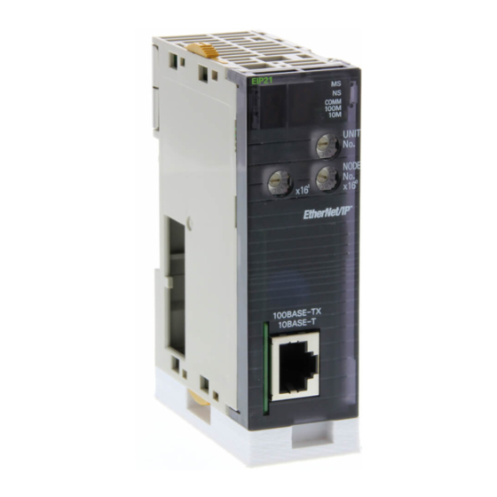
Nomenclature and Functions Section 2-2 Nomenclature and Functions 2-2-1 Nomenclature and Functions CS1W-EIP21 EIP21 LED Indicators COMM 100M UNIT Unit number setting switch Node address NODE setting switches ×16 ×16 ADDRESS Label showing 192.168.250.1 IP address SUBNET MASK 255.255.255.0 Backplane... - Page 51 IP address and subnet mask on the label, and affix the label to the front of the Unit. When this label is affixed to the front of the Unit, it is easy to confirm the Unit’s IP address and subnet mask.
- Page 52 The COMM, 100M, and 10M indicators indicate the status of Ethernet com- munications. The MS and NS indicators can be green or red. The COMM, 100M, and 10M indicators are yellow. These indicators can be lit, flashing, or not lit. The fol- lowing table shows the meaning of these indicator conditions.
- Page 53 10BASE-TX link not established Seven-segment Display When the power is turned ON (or the Unit is restarted), all of the segments will flash twice, the IP address set in the EtherNet/IP Unit or built-in EtherNet/IP port will be displayed on the 7-segment display just once, from right to left.
- Page 54 Unit. The last digit of the Unit's IP address is displayed in hexadecimal. • There is no particular priority to the order in which the errors are dis- played. All of the errors are displayed repeatedly in order.
-
Page 55: Switch Settings
Note The unit number is factory-set to 0. The unit number can be set to any number in the setting range (0 to F), as long as the same number is not set on another CPU Bus Unit in the same PLC. - Page 56 01 to FE Note The node address is factory-set to 01. With the default settings, the values set on these switches become the last two digits of the local IP address of the Ether- Net/IP Unit or built-in EtherNet/IP port.
-
Page 57: Selecting The Network Devices
Tsuko Company Japan Headquar- ters Note (1) Always use a switching hub when using tag data links in the network. (2) If a repeater hub is used for EtherNet/IP tag data links (cyclic communi- cations), the network’s communications load will increase, data collisions will occur frequently, and stable communications will be impossible. -
Page 58: Switching Hub Functions
This function controls the priority of packet transmissions so that packets can Function for TCP/UDP be sent with higher priority to a particular IP address or TCP (UDP) port. The Port Numbers (L4) TCP and UDP protocols are called transport layer protocols, leading to the name L4 (layer 4) QoS function. - Page 59 L2 switching hubs (with or without multicast fil- tering). • The tag data links are set to share the same data with all nodes in the net- work. (The multicast packets are transferred to all nodes in the network, just like a broadcast.)
- Page 60 Section 2-3 Selecting the Network Devices L3 Switching Hub with We recommend this kind of switching hub when both tag data links and mes- Multicast Filtering and L4 sage communications are executed. QoS Functions By setting tag data links for higher-priority transmission, it is possible to pre- vent problems such as transmission delays due to message communications traffic and packet losses due to buffer overflow.
-
Page 61: Installation And Initial Setup
I/O Table Overview........ -
Page 62: Overview Of Initial Setup Procedures
• If you want to store the setting in the CPU Unit, set it in the EtherNet/ IP Unit’s allocated DM area within the CPU Unit. • If you want to store the setting in the Unit, set the IP address in the Edit Parameters Dialog Box of the I/O Table Dialog Box from the CX-Pro- grammer, and transfer the setting to the Unit. - Page 63 Controller Link data link parameters. Refer to 3-9 Tag Data Link Parameters or SECTION 6 Tag Data Link Functions. 2. Using the Tag Data Link Setting Function in the Network Configurator to Set the Parameters With this method, you can set the connections that define the tag data links for each EtherNet/IP node.
-
Page 64: Switch Settings
When IP addresses are generated automatically (either dynamic or passive), Addresses the rightmost byte of the host ID of the IP address is set to the same value as the node address. (Refer to Section 5 Determining IP Addresses.) If the same node address value cannot be used, the IP address table method or the com- bined method must be used for address conversion. -
Page 65: Cj-Series Ethernet/Ip Units And Cj2 Built-In Ethernet/Ip Port
EtherNet/IP Units or built-in EtherNet/IP ports. The setting, however, must be made within a range of 01 to FE. If a value outside of this range is set, the MS indicator will light red, the 7-segment display will indicate code H4 (node address setting error), and the EtherNet/IP Unit or built-in EtherNet/IP port will stop operating. -
Page 66: Mounting To A Plc
EtherNet/IP Units can be mounted in a CJ-series CPU Rack or a CJ-series Expansion CPU Rack. Connect the EtherNet/IP Unit in any of the positions shown below using the sliders on the top and bottom of the Unit. Up to seven EtherNet/IP Units can be mounted for a CJ2H-CPU@@-EIP CPU Unit (enabling up to eight EtherNet/IP ports if you include the built-in EtherNet/IP port). -
Page 67: Mounting
1. Hook the claw on the top of the Unit onto the Backplane. Claw Backplane 2. Insert the Unit into Backplane connectors and securely tighten the screw at the bottom of the Unit. Tighten the screws to a torque of 0.4 N·m. -
Page 68: Handling Precautions
Mounting to a PLC Section 3-3 3. When removing the Unit, first loosen the screw at the bottom of the Unit. Fixing screws Note When mounting the Unit, provide the clearance shown below to facilitate easy mounting or dismounting. Duct 20 mm min. -
Page 69: Network Installation
• Do not install Ethernet equipment near sources of noise. If a noisy envi- ronment is unavoidable, take adequate measures against noise interfer- ence, such as installing network components in grounded metal cases or using optical cable in the system. - Page 70 Network Installation Section 3-4 • Press the cable connector in firmly until it locks into place at both the switching hub and the EtherNet/IP Unit. • Do not lay the twisted-pair cable together with high-voltage lines. • Do not lay the twisted-pair cable near devices that generate noise.
-
Page 71: Using Contact Outputs (Common To All Units)
Cable Location Separate the transceiver cable or twisted-pair cable connecting the EtherNet/ IP Unit as far from the wiring to the Contact Output Units as possible. The coaxial cable must also be placed as far away from the Contact Output Units and their wiring as possible. -
Page 72: Connecting To The Network
Not used. Hood Frame ground 3-5-2 Connecting the Cable !Caution Turn OFF the PLC’s power supply before connecting or disconnecting twisted- pair cable. !Caution Allow enough space for the bending radius of the twisted-pair cable as shown in below. 35 mm... - Page 73 Section 3-5 1,2,3... 1. Lay the twisted-pair cable. 2. Connect the cable to the switching hub. Be sure to press in the cable until it locks into place. 3. Connect the twisted-pair cable to the connector on the EtherNet/IP Unit.
-
Page 74: Creating I/O Tables
3-6-1 I/O Table Overview I/O tables are used to identify Units mounted to the PLC, and to allocate I/O to them. With CS-series and CJ-series PLCs, whenever there is a change to the Unit configuration it is necessary to create I/O tables and register the mounted Units in the CPU Unit. - Page 75 Section 3-6 (2) With the CJ2H-CPU@@-EIP and CJ2M-CPU3@ CPU Units, the built-in EtherNet/IP port is set in the I/O tables by default and cannot be changed. It is not necessary to register it in the I/O tables. Use the following procedure to create the I/O tables.
- Page 76 Connect Button. 3. If the connection process is successful, the system will be connected on- line. Here, check the operating mode of the PLC. If the operating mode is − not PROGRAM mode, change the mode by selecting PLC Operating −...
- Page 77 Transfer from PLC from the menus. Note Creating I/O tables is not required if the built-in EtherNet/IP port of a CJ2 CPU Unit is used. It is registered as a built-in port/Inner Board with a model number of CJ2B-EIP21 for the CJ2H and a model number of CJ2M-EIP21 for the...
-
Page 78: Setting The Local Ip Address
Setting the Local IP Address Section 3-7 Setting the Local IP Address This section describes the 3 ways to set the local I/O address of an EtherNet/ IP Unit or built-in EtherNet/IP port. Method 1: Using the default IP address: The default IP address is 192.168.250.Node_address. - Page 79 This method can be used to set IP addresses from the CX-Programmer. For details, refer to 3-8 TCP/IP and Link Settings. If the IP address is set in the TCP/IP Tab Page, that IP address setting will be displayed in the IP Address Display/Setting Area (words m+98 and m+99) in...
-
Page 80: Tcp/Ip And Link Settings
Unit. Note Unlike the Ethernet Units, the TCP/IP settings of the EtherNet/IP Unit and built-in EtherNet/IP port are not stored in the CPU Unit’s CPU Bus Unit Sys- tem Setup Area. 3-8-1 Setting Procedure with the CX-Programmer 1,2,3... - Page 81 4. Place the CX-Programmer online with the PLC and transfer the settings to the EtherNet/IP Unit or built-in EtherNet/IP port. 5. After transferring the settings, a message will ask if you want to restart the EtherNet/IP Unit or built-in EtherNet/IP port. The Unit/port must be restart- ed to enable the settings.
- Page 82 CPU Unit’s allocated DM Area or using the default IP address (default IP address = 192.168.250.Node_address). When the IP address is set on the TCP/IP Tab Page, it will be stored as the IP address in the DM Area words allocated to the Unit/port as a CPU Bus Unit.
-
Page 83: Making Tcp/Ip Settings With The Network Configurator
Operates in 100Base-TX, full duplex. Note Adjust the EtherNet/IP Unit’s link settings to match the communications set- tings of the connected switching hub. If the settings do not match, the link will become unstable and prevent normal communications. The following table shows the allowed settings for each switching hub communications mode. - Page 84 In the following example, the settings are all at their default values. 3. Enter the IP address to set and press the Get from the Device Button. The present setting will be obtained. Change the IP address in the New Con- figuration Box if required.
-
Page 85: Tag Data Link Parameters
Unit or built-in EtherNet/IP port. The parameter settings are saved in flash memory in the EtherNet/IP Unit or CPU Unit. (See note.) Note The CPU Bus Unit Setup Area is not used for tag data link settings for an EtherNet/IP Unit or built-in EtherNet/IP port. This point is different from the operation of Ethernet Units. - Page 86 Tag Data Link Parameters Section 3-9 The following method can be used to easily set the data links shown in the fol- lowing figure using a wizard in the EtherNet/IP Datalink Tool. Node #2: CJ1H-CPU67H Node #3: CJ1H-CPU67H Node #1: CJ1H-CPU67H (IP address: 192.168.250.1)
- Page 87 4. In the Datalink Wizard Dialog Box, enter 50 words starting from memory address W000 for area 1 and 100 words starting from D00050 for area 2, and then press the OK Button. 5. The data link settings will be automatically created in the window of the −...
- Page 88 Section 3-9 6. In the Device Configuration Window of the Network Configurator, a mark will be added to each EtherNet/IP Unit to show that data links have been set. 7. Connect the Network Configurator to the EtherNet/IP network and select −...
-
Page 89: Other Parameters
EtherNet/IP Unit or CPU Unit. (See note.) Note The CPU Bus Unit Setup Area is not used for tag data link settings for an EtherNet/IP Unit or built-in EtherNet/IP port. This point is different from the operation of Ethernet Units. - Page 90 Select this check box to refuse connection requests from any IP address not set as the target IP address when the server/client setting is set to a server and the target IP address is set to any value other than 0.0.0.0.
- Page 91 CPU Unit clock. When the specified time arrives, the SNTP server will be accessed and the clock in the CPU Unit will be set to the time on the SNTP server. Server Specification Type Specifies whether to use an IP address or a domain name (i.e., host name) to specify the SNTP server to use for automatic time adjustment.
- Page 92 Not use SNMP service or Specifies whether to use the SNMP. Use SNMP service If not using the SNMP service is specified, an SNMP manager will not be able to connected from an external device. SNMP Port Sets the port number to use when connecting from an SNMP man- ager.
-
Page 93: Communications Test
Input the following command at the host computer’s prompt ($): $ ping IP_address(host_name) The destination is specified by its IP address or host name. If the host name is used, the host name must be defined in the /etc/hosts file. - Page 94 Communications Test Section 3-11 Application Example In this example, a PING command is sent to the node at IP address 130.25.36.8. The “$” in the example represents the host computer prompt. Normal Execution ← Executes the PING command. $ ping 130.25.36.8 PING 130.25.36.8: 56 data bytes...
-
Page 95: Memory Allocations
User Settings Area ........ -
Page 96: Overview Of Memory Allocated To The Ethernet/Ip Unit
Section 4-1 Overview of Memory Allocated to the EtherNet/IP Unit Overview of Memory Allocated to the EtherNet/IP Unit The following CPU Unit words are allocated to the EtherNet/IP Unit or built-in EtherNet/IP port. • CPU Unit’s allocated CIO Area words Contains software switch and status information. - Page 97 Section 4-1 Overview of Memory Allocated to the EtherNet/IP Unit CPU Unit EtherNet/IP Unit ● Allocated CIO Area words (Allocated to the Unit as a CPU Bus Unit.) Local memory CIO 1500 Flags and control bits CIO 1501 Unit number 0...
-
Page 98: Cio Area Allocations
The layout can be selected in the Status Area settings in the Edit Parameters Dialog Box from the CX-Programmer. To set a customer areas, select User defined for the Layout Type on the Sta- tus Area Tab Page. -
Page 99: Details Of The Allocated Cio Area Words
EtherNet/IP Unit → CPU Unit FINS/TCP Connection Status n+24 Note The reserved words are regularly refreshed with all zeroes. The functions of the allocated CIO Area words are described in the following section. 4-2-2 Details of the Allocated CIO Area Words... - Page 100 Once the tag data links have stopped, the EtherNet/IP Unit automatically turns OFF the Tag Data Link Stop Bit. Do not force this bit ON or OFF until it is automatically turned OFF by the Unit. Adjust Clock Bit (Bit 5) Automatically adjust the time on the clock by switching this bit from OFF to ON.
- Page 101 CPU Unit) (n + 6 to n + These words show the error status of nodes 0 to 63 only. If it is necessary to show the error status of nodes higher than node 63, select “user settings” as the layout pattern.
- Page 102 Indicates that an error occurred that is related to EtherNet/IP Unit operation. This flag is turned ON when any bit in Unit Status 1 is ON. (Bits 1 to 15 are logi- cally ORed.) Unit Indicates that a Unit error did not occur.
- Page 103 Setting Error error in the allocated CIO Area’s layout settings. When this error occurs, the allo- cated CIO Area layout is set to the default pattern. In the following cases, how- ever, the allocated CIO Area layout is set to the user-set pattern.
- Page 104 Unit Indicates that the tag data link is stopped. Turned ON in the following cases. • The Unit is set as the origi- nator and the power supply was turned ON or the Unit was restarted. • The Unit is set as the origi- nator and the Tag Data Link Start Bit was turned ON.
- Page 105 Also turned OFF when an error log clear request is received. Communications Word n+12 contains status flags related to the tag data links, as shown in the Status 1 following diagram. (EtherNet/IP Unit to CPU Unit) (n + 12)
- Page 106 ON if a tag database error Error occurs in the CPU Unit when a symbol name is used incor- rectly in a setting for the Eth- erNet/IP Unit or built-in EtherNet/IP port (tag data link, status area allocations setting, etc.). (CJ2H-CPU6@-...
- Page 107 CIO Area Allocations Section 4-2 Communications Word n+13 contains status flags related to the Ethernet, as shown in the fol- Status 2 lowing diagram. (EtherNet/IP Unit to CPU Unit) (n + 13) n+13 Link Status FTP Status Name Status Manipulated...
- Page 108 CIO Area Allocations Section 4-2 Name Status Manipulated Unit operation IP Router Table Unit ON when the IP router table Error information is incorrect. Unit OFF when the IP router table information is correct. DNS Server Error Unit One of the following errors occurred when using the DNS server.
- Page 109 EtherNet/IP Unit as the originator. (EtherNet/IP Unit to These words show the status of nodes 0 to 63 only. If it is necessary to show CPU Unit) (n + 16 to n the status of nodes higher than node 63, select “user settings” as the layout + 19) pattern.
- Page 110 CIO Area Allocations Section 4-2 Name Status Manipulated Unit operation FINS/TCP Connec- Unit Turned ON by the Unit when a tion 2 connection is established. Unit Turned OFF by the Unit when the connection is terminated. FINS/TCP Connec- Unit Turned ON by the Unit when a tion 15 connection is established.
-
Page 111: Dm Area Allocations
(1)(2).(3)(4).(5)(6).(7)(8) (Hex) IP address: (1)(2).(3)(4).(5)(6).(7)(8) (Hex) If the local IP address is set to a value other than 0.0.0.0 in the TCP/IP Config- uration, this area (words m+98 and m+99) will act as an IP Address Display Area and the local IP address set in the TCP/IP Configuration will be read and stored here when the power is turned ON or the Unit restarted. - Page 112 IP address was set in the IP Address Display/ Setting Area words beforehand. (2) It is not possible to set the following IP addresses. If any of these values are set, the ERH indicator will flash.
-
Page 113: User Settings Area
4-4-1 Overview of the User Settings Area When the layout of the allocated CIO Area words is set to user settings, the user settings area can be used in addition to the allocated CIO Area words and allocated DM Area words. - Page 114 These flags indicate the connection status of the target nodes. With revision 2 Table (EtherNet/IP or higher, the flag turns ON after all data for multiple connections for individual target devices is refreshed in the CPU Unit. With revision 1, each flag immedi- Unit to CPU Unit) ately turns ON when all connections are established.
- Page 115 These flags indicate the error status (logical OR of fatal and non-fatal errors) Error Information of the target node PLCs, and are valid only when the EtherNet/IP Unit is the originator. The flags are valid only when the corresponding Normal Target (EtherNet/IP Unit to Node Flag is ON.
-
Page 116: Auxiliary Area Data
Section 4-5 Auxiliary Area Data Auxiliary Area Data The following table and descriptions cover the words and bits in the CPU Unit’s Auxiliary Area that are related to the EtherNet/IP Unit. 4-5-1 Read-only Bits/Words Word(s) Bit(s) Name Function Settings A202... -
Page 117: Read/Write Bits (User Settings)
When an error occurs in a data exchange between 0: No error A41715 Unit Number Flags the CPU Unit and a CPU Bus Unit, the CPU Bus 1: Error Unit Error Flag (A40207) and the corresponding flag in A417 are turned ON. Bits 00 to 15 correspond to unit numbers 0 to F. - Page 118 Section 4-5 Auxiliary Area Data...
-
Page 119: Determining Ip Addresses
Private and Global Addresses ........ -
Page 120: Ip Addresses
5-1-1 IP Address Configuration IP addresses are made up of 32 bits of binary data divided into four 8-bit fields called octets. These four octets provide the network number (net ID) and host number (host ID). The network number identifies the network, and the host number identifies the node (or host) on the network. -
Page 121: Ethernet/Ip Unit Ip Address Settings
Subnet mask 1 1 1 1 1 1 1 1 1 1 1 1 1 1 1 1 1 1 1 1 1 1 1 1 0 0 0 0 0 0 0 0 = FF FF FF 00 Network number... -
Page 122: Ip Addresses In Fins Communications
Note Use the Node Address Setting Switches (NODE NO.) on the front of the Eth- erNet/IP Unit or, for the built-in EtherNet/IP port, on the front of the CPU Unit to set the FINS node address. Allocating Addresses to EtherNet/IP Units and Built-in EtherNet/IP Ports... - Page 123 With these methods, the IP address and the FINS node address setting in the EtherNet/IP Unit or built-in EtherNet/IP port have no particular relationship. Set both the FINS node address and the IP address so that they are not dupli- cated in the network.
-
Page 124: Pairing Addresses In Internal Tables
With the dynamic method, data in an internal table that has been generated can be dynamically converted according to FINS messages received from remote nodes. This is enabled when the remote node is a device such as a personal computer and IP addresses are dynamically changed by a method such as DHCP. - Page 125 With this method, FINS node addresses are converted to IP addresses based on a preset correspondence table (IP address table). The IP address table is set on the FINS/UDP Tab Page of the Edit Parameters Dialog Box of the CX-Programmer. Nodes can be registered even if they are...
- Page 126 When the Unit is turned ON or restarted and the IP address of a remote FINS node is not registered in the IP table, the IP address can be changed dynamically according to FINS mes- sages received from the remote node.
- Page 127 UDP port number. • If the command data is for any other Unit, such as the CPU Unit, a FINS response will be sent to the UDP port number set as the FINS/UDP port...
- Page 128 FINS/TCP connections in the FINS/TCP Tab Page of the CX-Programmer’s Edit Parameters Dialog Box. 2. The remote node (i.e., the server) is notified of the FINS node address for the local device. 3. Notification is received from the remote node (i.e., the server) of the re- mote node's FINS node address.
- Page 129 Local Device: FINS/TCP Server 1,2,3... 1. A request to open a connection is received in TCP/IP protocol from the re- mote device (i.e., the client, either a personal computer, an EtherNet/IP Unit or built-in EtherNet/IP port), and the connection is established.
-
Page 130: Application Examples
2. Set IP addresses for the devices to be connected. Set the IP address for the remote EtherNet/IP Unit or built-in EtherNet/IP port (i.e., the server) connected by FINS/TCP. This setting must be made if this EtherNet/IP Unit will be used as a FINS/ TCP client. 5-2-3... -
Page 131: Related Products And Communications/Setting Methods
In communications involving previous models, multiple communications appli- cations were configured on personal computers according to data accessing uses, and the fact that no more than one UDP port number for FINS commu- nications could be used on any given computer created a problem. This Eth-... - Page 132 IP Addresses in FINS Communications Section 5-2 Product Model/Series/ Supports automatic Version generation method (dynamic)? Programmable Terminal NS Series No: Set manually so that automatic settings can be Open Network Controller (ONC) used with the automatic generation method. Models Supporting...
-
Page 133: Pairing Ip Addresses And Fins Node Addresses
DHCP. 5-2-5 Pairing IP Addresses and FINS Node Addresses The following table shows the methods for pairing IP address and FINS node addresses, and the relation between fixed and variable address, for both FINS/UDP and FINS/TCP. Communi-... -
Page 134: Private And Global Addresses
Ethernet (EtherNet/IP) Private address Private address Communications Services A global address is required for the IP addresses of the EtherNet/IP Units and That Require Global built-in EtherNet/IP port when the following communications services are Addresses for EtherNet/IP used over the Internet. -
Page 135: Private And Global Addresses
A device such as a personal computer (with a FINS application, including the CX-Programmer) cannot connect online and communicate over the Internet with an EtherNet/IP Unit or built-in EtherNet/IP port that has a pri- vate address. FINS communications are also not possible over the Inter- net between EtherNet/IP Units and or built-in EtherNet/IP ports with private addresses. - Page 136 Before doing so, be sure to consult with a network specialist and consider installing a firewall. Once a firewall has been set up by a communications technician, on the other hand, there may be some applications that cannot be used. Be sure to check...
-
Page 137: Ethernet/Ip Unit With A Global Address
• The IP address table method is used as the IP address conversion method of the EtherNet/IP Unit or built-in EtherNet/IP port. • The TCP port number to be used for FINS/TCP cannot be used if prohib- ited by a firewall in the communications path. - Page 138 It is recommended that the user contract with a communications company for a dedicated line, rather than using a general line such as a broadband line. Also, be sure to consult with a network specialist and consider security measures such as a firewall.
-
Page 139: Tag Data Link Functions
Data Link Data Areas ........ -
Page 140: Overview Of Tag Data Links
PLCs or between PLCs and another device. I/O memory addresses (e.g., in the CIO or DM Area) and symbols can be assigned to tags. The set- tings for tag data links are made using the Network Configurator. Refer to 6-2 Setting Tag Data Links for information on how to make the settings. - Page 141 (i.e., I/O allocation settings) that were created using the CX-Programmer into the Network Configurator. Output tags can be defined to clear output data to 0 or to hold the output data when PLC outputs are turned OFF.
- Page 142 The packet interval can be set to between 0.5 and 10,000 ms in units of 0.5 ms for the CJ2B-EIP21 (built-in EtherNet/IP port on the CJ2H), CS1W-EIP21, or CJ1W-EIP21.
-
Page 143: Tag Data Link Functions And Specifications
This applies only if one output tag set is sent to multiple nodes using a multi- cast connection with one packet, the connection type of the connections that receive the output tag set is multicast, and the connection I/O types, packet intervals (RPI), and timeout values are all the same. -
Page 144: Data Link Data Areas
Each tag set represents the data that is linked for a tag data link connection. Tag data links are thus created by connecting one tag set to another tag set. A tag set name must be set for each tag set. Note A connection is used to exchange data as a unit within which data concur- rency is maintained. - Page 145 Tag c Tag g EtherNet/IP There are both input and output tag sets. Each tag set can contain only input tags or only output tags. The same input tag cannot be included in more than one input tag set. Number of Tags in Tag Each tag set can contain one or more tags.
- Page 146 This function reads the operating status (operat- ing and error status) of the CPU Unit of the PLC in which the EtherNet/IP Unit is mounted, and includes the PLC status as status flags in the data trans- ferred by the tag data links.
- Page 147 To receive the PLC status, specify the PLC status in an input (consume) tag in the reception tag set as well. When the PLC status is specified in an input tag, the PLC status flags will be reflected in the corresponding location in the tag data link’s Target Node PLC Operating Flags and Target Node PLC Error...
- Page 148 Network Configura- tor. The data in this table is refreshed when neces- sary. Note When the PLC status is not selected in the input (consume) tags, the PLC sta- tus information (16-bit data) can be used as reception data.
-
Page 149: Setting Tag Data Links
Menu. ■ Starting from the IO Table Dialog Box in CX-Programmer To start the Network configurator, select the Unit in the PLC IO Table Dialog Box and select either of the options for Start Special Application from the pop-up menu. Only operation will be started even if Start with Settings Inher-... - Page 150 Section 6-2 When the Network Configurator starts, the following window will be displayed. Main Window The Main Window consists of a Hardware List and a Network Configuration Window, as shown in the following diagram. Network Configuration Window: Displays the layout and network configuration of devices that are set and monitored.
- Page 151 When two or more networks are being managed, a new Network Configura- tion Window can be added by selecting Network - Add. To change the name displayed in the Network Tab Page, select Network - Property. The name set in the Comment Field of the Network Property Win-...
-
Page 152: Tag Data Link Setting Procedure
Status with the Network Configurator). ↓ Check that the output tag data is updated in the input tag by using the CX-Program- mer's Watch Window or PLC memory function. Note Refer to the CX-Programmer Operation Manual (Cat. No. W446) for the operat- ing procedures. -
Page 153: Registering Devices
Section 6-2 Setting Tag Data Links IP port on a CJ2H-CPU@@-EIP CPU Unit. Make sure you are using the cor- rect specifications for the application. Refer to 2-1-3 Communications Specifications for the communications specifi- cations. 6-2-3 Registering Devices Register all of the devices required in the equipment (such as EtherNet/IP Units performing tag data links) as a network configuration. -
Page 154: Creating Tags And Tag Sets
Change Node Address. 3. Set the IP address to match the node address (IP address) actually being used in the device. 4. Repeat steps 1 to 3, and register all of the devices participating in the tag data links. 6-2-4... - Page 155 Creating a Tag Set 1,2,3... 1. Double-click the icon of the device (for which a tag set is being created) to display the Edit Device Parameters Dialog Box. Right-click the icon to dis- play the pop-up menu, and select Parameter - Edit.
- Page 156 3. Click the Edit Tags Button. The Edit Tags Dialog Box will be displayed. Register the input (consume) tags and output (produce) tags separately. 4. Click the In - Consume Tab, and click the New Button. The Edit Tag Dialog Box will be displayed.
- Page 157 Bank 0 hex E0_00000 to E0_32767 Bank 18 E18_00000 to E18_32767 Note (a) The H, W, D, and E characters can also be input in lower case as h, w, d, and e. (b) Be sure to directly enter the CPU Unit's I/O memory address (e.g., 100, W100, D0) or a network symbol as a character string.
- Page 158 A tag set can contain up to 8 tags, but tag sets will be registered with one tag per tag set if the tags are registered as tag sets. In this case, the Yes Button is...
- Page 159 Setting Tag Data Links If the No Button is clicked, more tags can be registered at the end of the tag set. Refer to step 18 for details on adding tags to the end of the tag set. Changing and Registering 11.
- Page 160 Delete Button in the Edit Tag Dialog Box. (If there are other tags registered in that tag set, it is possible to delete just one tag by selecting the tag that you want to delete in the Edit Tag Set Dialog Box and clicking the Button.)
- Page 161 Edit Button. The Edit Tag Set Dialog Box will be displayed. The Tag List on the left side of the dialog box shows the tags that are al- ready registered, and the Candidate Tag List on the right side of the dialog box shows the other tags that have not been registered yet.
- Page 162 Section 6-2 Setting Tag Data Links 18. If you want to just add new tags and register the tag set, first register the tags with steps 1 to 9. In this example, input tags D00004 and D00005 have been newly added.
- Page 163 22. Select the tags that you want to add from the Candidate Tag List and click Button. Up to 8 tags can be registered in a tag set, or up to 7 tags can be registered and two byes will be added to the size if the PLC status is included in the tag set.
- Page 164 Parameter Dialog Box will be displayed. You can also right-click the icon and select Device - Parameters - Edit from the pop-up menu. 3. Click the Import Button on the Tag Sets Tab Page of the Edit Device Pa- rameter Dialog Box.
- Page 165 Setting Tag Data Links A confirmation message will be displayed. Click the Yes Button. The symbols will be imported as shown below on the Tag Sets Tab Page. Each symbol will be imported into a different tag set and the device param- eters will be automatically edited.
- Page 166 Programmer into one tag set, you must delete the input tags that were reg- istered to separate input tag sets. Select the tag sets for the symbols that are included in the one tag set and click the Delete Button. A confirmation message will be displayed. Click the No Button to delete only the tag sets.
- Page 167 Exporting Tags and Tag Sets with the Network Configurator 1,2,3... 1. Select To/From File - Export to file on the Tag Sets Tab Page in the Edit Device Parameters Dialog Box to export the tag and tag set information to...
- Page 168 1. In the project global symbol table for the CJ2H-CPU6@-EIP or CJ2M- CPU3@, right-click and select Import Network Variable from the pop-up menu. 2. You can add a tag as a network symbol by selecting and executing the CSV file exported using the Network Configurator. Note The following precautions apply when importing.
-
Page 169: Connection Settings
Section 6-2 6-2-5 Connection Settings After creating the tag sets, click the Connections Tab at the top of the Edit Device Parameters Dialog Box, and set the following connection information. • The target devices with which connections will be opened •... - Page 170 Target Node PLC Operating Flag, Target Node PLC Error Flag, Reg- istered Target Node Flag, and Normal Target Node Flag. By default, the target ID is automatically set to the rightmost 8 bits of the IP address. In the example above, the target device’s IP address is 192.168.250.2, so the device number is #002.
- Page 171 1,2,3... 1. Select the Connection Tab and then click the New Button. The following Edit Connection Dialog Box will be displayed according to the type of device that is selected. Using an OMRON EtherNet/IP Unit or Built-in EtherNet/IP Port as the...
- Page 172 The Connection Structure Field and the following items will not be displayed if the Hide Detail Button is pressed. Packet Interval (RPI) Sets the data update cycle (i.e., the packet interval) of each connection between the originator and target.
- Page 173 Sets the time until a connection timeout is detected. The time out value is set as a multiple of the packet interval (RPI) and can be set to a 4, 8, 16, 32, 64, 128, 256, or 512 multiple. The default setting is 4× the packet interval (RPI).
- Page 174 Confirming the Connections Settings 1,2,3... 1. An overview of the connections set in the Register Device List is displayed in the Connections Tab Page. 2. Click the OK Button. The following kind of diagram will be displayed. Indicates the IP address of the originator where the connection was set.
- Page 175 Setting Tag Data Links Section 6-2 4. If the tag set’s size is changed in either the originator or target after the connection was set, the size will not match the other node and a parameter data mismatch will occur. In this case, if the connection settings have been changed, be sure to check the connections.
- Page 176 Connection EtherNet/IP 1,2,3... 1. Set the same tag set names for the output and input tag sets for the con- nection. The tag set names can also include forward and backward el- lipses. 2. Select Auto Connection from the Network Menu. The connections will be set automatically.
- Page 177 Click the OK Button to start processing. 4. A device connection structure tree will be displayed when processing has been completed. 5. Use the device connection structure tree as required to change the RPI and timeout settings. Device Connection Connection settings can be displayed on the network configuration. Select Structure Tree View Device’s Connection Structure Tree from the Network Menu.
-
Page 178: Setting Tags Using Data Link Tool
IP Units and built-in EtherNet/IP ports. • Tags must be set using I/O memory addresses. • A maximum of two tags (area 1 and area 2) can be set in one tag set. Select Network - EtherNet/IP Datalink Tool from the menus in the Network Configurator after you have registered all the devices to start the EtherNet/IP Datalink Tool. - Page 179 PLC are turned OFF from the CPU Unit. • Area 1, Link CH: The I/O memory address of the first word in link area 1 • Area 1, Size: The number of words in link area 1. (See note.) •...
- Page 180 (Network Configurator 1.21 or higher). This value is automatically displayed after the sizes of areas 1 and 2 are entered. • Node: For an input tag, this is the IP address of the node that provides the output. For an output tag, “-” will be entered automatically.
- Page 181 Section 6-2 Setting Tag Data Links 2. Select the memory area (here, W) in the Memory Field and enter the start- ing address (here, 0) and number of words (here, 50) in the Start Address and Size Fields for Area 1.
- Page 182 Section 6-2 Setting Tag Data Links If the creating the data link table is continued, the data link table will be cre- ated with the same size of data link for all registered nodes. Examples are shown below. Automatic Allocation Results for Node 1 (IP Address: 192.168.250.1)
- Page 183 Setting Tag Data Links Automatic Allocation Results for Node 3 (IP Address: 192.168.250.3) 6. After entering all of the settings in the data link table, select Save from the File Menu. A consistency check will be performed on the table and the re- sults will be displayed.
-
Page 184: Creating Connections Using The Wizard
Wizard. 1,2,3... 1. Set tags and tag sets for all devices before starting the Wizard. Refer to 6- 2-4 Creating Tags and Tag Sets for the setting procedure. 2. For tag data links between OMRON PLCs, a connection is created in the PLC (i.e., the originator device) that receives data as input data. - Page 185 3. Create the connection following the instructions that are given by the Wiz- ard after the Wizard starts. (See the following figure.) 4. A list of tag sets is displayed on the right side of the Wizard Dialog Box with target devices that support receiving input data.
- Page 186 • If there is no applicable input tag set, you can edit a tag set or create a new one by using the Edit Tag Sets Button and Edit Tag Button.
-
Page 187: Creating Connections By Device Dragging And Dropping
1,2,3... 1. Set the tags and tag sets for the target device that will be dragged. a. Refer to 6-2-4 Creating Tags and Tag Sets for information on creating the settings if the target is one of the OMRON EtherNet/IP devices giv- en above. - Page 188 • If there is no applicable tag set at the originator, you can create a new one by using the Edit Tag Sets Button and Edit Tag Button.
-
Page 189: Connecting The Network Configurator To The Network
When creating the connection has been completed, the in- put tag set and output tag set will be blank. Next, you can continue to cre- ate connections by selecting the connection I/O type and setting a tag set. - Page 190 Network Configurator is connected online properly, On-line will be dis- played in the status bar at the bottom of the window. The network connec- tion icon will be displayed in blue in the Network Tab Page in which the Network Configurator is connected.
- Page 191 Section 6-2 Setting Tag Data Links 3. Input the EtherNet/IP Unit’s unit number in the Unit No. Field, select the connecting COM port number, and click the OK Button. Usually, the Baud Rate is left at this setting. The following dialog box will be displayed.
- Page 192 2. Select Network - Connect. The Setup Interface Dialog Box will be dis- played. 3. Set the port type to either USB or serial. 4. Set the port to use and then click the OK Button. (Leave the baud rate at the default setting.) The following dialog box will be displayed.
- Page 193 Setting Tag Data Links Select the TCP port of the EtherNet/IP Unit. 7. Select the port for the EtherNet/IP Unit and then click the OK Button. The Network Configurator will be connected to the EtherNet/IP network. If the Network Configurator goes online normally, “On-line” will be displayed in the status bar at the bottom of the window.
- Page 194 2. Select Network - Connect. The following Setup Interface Dialog Box will be displayed. 3. Click the Setup Button in the Setup Interface Dialog Box. The Registration of the connection Dialog Box will be displayed. Enter the network informa- tion for the connection destination, and then click the Add Button to regis- ter the settings.
- Page 195 “On-line” will be displayed in the status bar at the bottom of the window when connection has been properly made online. Note A list of nodes on the EtherNet/IP network you are attempting to connect to will be displayed when the Refresh Button or the icon ( ) at the left of TCP:2...
-
Page 196: Downloading Tag Data Link Parameters
• For EtherNet/IP Units with revision 1, tag data link parameters can be downloaded only when the CPU Unit is in PROGRAM mode. • Even for Units with revision 2 or later, all CPU Units must be in PRO- GRAM mode to download the parameters if any Units with revision 1 are... - Page 197 3. Click the Yes Button to download the tag data link parameters to the Eth- erNet/IP Unit. The following dialog box will be displayed if any of the CPU Units is not in PROGRAM mode. • Display When All EtherNet/IP Units and Built-in EtherNet/IP Ports are...
- Page 198 The Download with Current mode Button can be clicked to download load the parameters even when one or more CPU Units is in RUN or MON- ITOR mode. • Display When Even One EtherNet/IP Unit Is Revision 1...
-
Page 199: Uploading Tag Data Link Parameters
Setting Tag Data Links Section 6-2 If the operating mode of one or more CPU Units was changed to download the parameters, the CPU Units can be returned to the previous operating mode. If the No Button is clicked, the CPU Units will remain in PROGRAM mode. -
Page 200: Verifying The Tag Data Links
Setting Tag Data Links Section 6-2 Select the icon of the EtherNet/IP Unit from which you want to upload. To select multiple nodes, press and hold the Shift Key while selecting addi- tional icons. (In the following example, 2 nodes are selected: 192.168.250.1 and 192.168.250.2.) - Page 201 1,2,3... 1. Connect the Network Configurator to the network. 2. The following progress monitor will be displayed to show the progress as data is read from the network and compared. 3. The results of the comparison between the network configuration file and data from the network are displayed as follows.
- Page 202 1,2,3... 1. Connect the Network Configurator to the network. 2. Click the icon of the EtherNet/IP Unit that is to be verified. To select multiple nodes, hold down the Shift Key while clicking the icons. (In the following ex- ample, the 192.168.250.1 and 192.168.250.2 nodes are selected.) With the icons selected, right-click and select Parameter - Verify from the pop-up menu.
-
Page 203: Starting And Stopping Tag Data Links
Tag data links will start operating automatically immediately after the tag data link parameters are downloaded from the Network Configurator. (They will also start automatically when the power to the PLC is turned ON or the CPU Unit is restarted.) -
Page 204: Clearing The Device Parameters
Stops all connections for which the device is the originator. Note Connections will be cut off if any of the following errors occurs in the CPU Unit that is the originator while tag data links are active. • Fatal CPU Unit error •... -
Page 205: Saving The Network Configuration File
1,2,3... 1. Select File - Save As. The following dialog box will be displayed. The File name Field will contain Untitled.nvf as the default file name. 2. Input the file name, and click the Save Button. -
Page 206: Reading A Network Configuration File
File - Save or clicking the Button. 4. You can select the Select target network Check Box in the Option Area to save a network configuration file with only the required networks. Select the check boxes of the networks to save and click the OK Button. - Page 207 If the network configuration file that you want to read is not displayed, change to (Look in) another folder. 2. When you click and select the network configuration file that you want to read, that file name will be displayed in the File name Field.
-
Page 208: Checking Connections
Section 6-2 Setting Tag Data Links 5. Select any of the options as necessary. The options are listed below. Option Function Select target network Allows you to select specific networks from the net- work configuration and open them. Add to current document... -
Page 209: Changing Devices
Select Change Device from the Device Menu to display a list of the devices that can be changed to. Select the desired device. A device can be changed only when there is complete or upward compatibility with the device being changed to. - Page 210 Communications normal (CPU Unit of PLC is in RUN or MONI- (blue) TOR mode.) Warning (A non-fatal error has occurred in the CPU Unit of the (yellow) PLC.) Alarm (A fatal error has occurred in the CPU Unit of the PLC.) (red)
-
Page 211: Ladder Programming With Tag Data Links
Ladder Programming Related to Tag Data Links If data in the ladder program is linked by tag data links, add conditions 1 to 4 in the ladder program for that data. If you want to use target node PLC flags as input conditions, add conditions 5 and 6. - Page 212 The following programming can be used to check for errors for each target Errors: Example 1 node. This programming is used to detect errors only after the data links for all nodes have started normally. Programming for Revision 2 or Higher...
- Page 213 Error output Local node Error output Example of Programming The following type of programming can be used to process data only when the to Process Data data links are operating normally. The parts of the ladder program that use the data link area for...
-
Page 214: Status Flags Related To Tag Data Links
Ladder Programming with Tag Data Links Note Even if an error occurs in communications with a target device, the input data from the target device will remain stored in words allocated in memory to the local node. To prevent malfunctions, write the ladder program so that input data processing will not be performed when the Unit Error Occurred Flag (word n+10 bit 00) is ON. -
Page 215: Message Communications Functions
Overview ........... . . FINS Message Communications........ -
Page 216: Overview
PLC, between two PLCs, between an OMRON PLC and a master made by another company, or between slaves. The messages can be used to send/receive data; read time data, error logs, and other data; or con- trol operation, e.g., by force-setting/resetting bits. - Page 217 Explicit message message function OMRON special message communications FINS message Ethernet (EtherNet/IP) network EtherNet/IP message communications Explicit message Note With the EtherNet/IP Unit or built-in EtherNet/IP port, message communica- tions are possible even if the I/O link function is disabled.
-
Page 218: Fins Message Communications
FINS messages are being used, the EtherNet/IP Units and built-in Ether- Net/IP ports must be registered in the CS/CJ-series PLC’s local network routing table. The commands will not be sent if the Unit is not registered in the routing tables. - Page 219 Section 7-2 FINS Message Communications Up to 8 network levels, including the EtherNet/IP network, can be crossed. Controller Link Unit Controller Link Unit CS/CJ-series EtherNet/IP Unit CS/CJ-series CPU Unit Remote I/O communications CS/CJ-series EtherNet/IP Unit Controller Link Ethernet (EtherNet/IP) CS/CJ-series EtherNet/IP Unit...
-
Page 220: Explicit Message Communications
Note The CS/CJ-series EtherNet/IP Units and built-in EtherNet/IP ports (CS1W- EIP21, CJ1W-EIP21, CJ2H-CPU@@-EIP, or CJ2M-CPU3@) contain a PLC Object, so that other devices can read/write the I/O memory of the CPU Unit with the built-in EtherNet/IP port or the CPU Unit to which the EtherNet/IP Unit... -
Page 221: Message Communications Specifications
CS/CJ-series EtherNet/IP Units and built-in EtherNet/IP ports (up to 3 levels). Different network Supports internetwork communications between the EtherNet/IP network type connected to a CS/CJ-series EtherNet/IP Unit or built-in EtherNet/IP port and other networks such as Controller Link or SYSMAC LINK (up to 3 lev- els). -
Page 222: Message Communications Error Indications
The time and date that the error occurred are also recorded together. The error log can be read or cleared from the CPU Unit by sending an FINS command to the EtherNet/IP Unit (Error Log Read/Clear). The contents of the error log can also be monitored from the Configurator. -
Page 223: Message Communications Errors
The following table shows the main errors that may occur when messages are sent or received. Refer to SECTION 14 Troubleshooting and Error Processing for corrective measures and details on errors that are recorded in error log but not indicated by the LED indicators. - Page 224 Section 7-6 Message Communications Errors...
-
Page 225: Fins Communications
Writing Programs ........ -
Page 226: Overview Of Fins Communications
FINS node address for FINS (the application layer) are used for the remote device. Also, 9600 is used as the default setting for the local UDP or TCP port number (i.e., the transport layer) for identifying the application layer, i.e., the FINS communications service. -
Page 227: Using The Fins/Udp And Fins/Tcp Methods
This a table of correspondences for remote FINS node addresses, remote IP addresses, TCP/ UDP, and remote port numbers. It is created automatically when power is turned ON to the PLC or when the Ethernet Unit is restarted, and it is automatically changed when a connection is established by means of the FINS/TCP method or when a FINS command received. -
Page 228: Fins/Udp Method
IP protocol. UDP/IP is a connectionless communications protocol. When a message is sent from one node to another, the two nodes have an equal rela- tionship and there is no clear connection. If using TCP is like making a tele- phone call, then UDP is more like delivering a memo by hand. - Page 229 UDP/IP, this port number must be allocated to the communi- cations service. The default setting for the UDP port number (i.e., the UDP port number of the EtherNet/IP Unit or built-in EtherNet/IP port) is 9600. To set another number, set the number on the FINS/UDP Tab Page of the CX-Programmers Edit Parameters Dialog Box.
-
Page 230: Fins/Tcp Method
• TCP/IP has various retry procedures, and this tends to lower its perfor- mance in comparison with UDP/IP. • There is a limit to the number of connections that can be made (i.e., 16 connections maximum), and any given node can communicate only with... - Page 231 FINS frames in order to serve as FINS frame delimiters. The length of the data in the following FINS frame is stored in the header, allowing the frame to be separated out by the remote node. With the EtherNet/IP Unit or built-in EtherNet/IP port and FinsGateway (Ver.
- Page 232 FINS/TCP connection status turns ON in the section of the CPU Bus Unit words allocated in the CIO Area. The bit turns OFF if the connection is termi- nated by a communications error or a FINS command (i.e., FINS/TCP CON- NECTION REMOTE NODE CHANGE REQUEST).
- Page 233 • If the connection is closed by the server. • If there is no response from the client when the keep-alive function is in effect. Even if the connection is closed at the FINS/TCP client, requests continue to be made to the FINS/TCP server every few seconds to open a connection.
- Page 234 Section 8-3 FINS/TCP Method • When routing tables are used for one or more other nodes on the same network It is not necessary to set routing tables if one Communications Unit is mounted to the PLC and the nodes are connected as one network.
-
Page 235: Routing Tables
Network #4 Note 1. The unit number is set (0 to F: 1 to 15) using the rotary switch on the front of the EtherNet/IP Unit (built-in port). 2. The network address is the number of the network (1 to 127) to which the Communications Unit or Board is connected. -
Page 236: Connecting And Using A Peripheral Device For The Plc
In the above example, the routing tables required for a message to reach PLC #4 from PLC #1 are shown. Additional settings would be required in the rout- ing tables for a message to reach PLC #1 from PLC #4. Refer to 8-4-3 Rout- ing Table Setting Examples for routing table setting examples. -
Page 237: Routing Table Setting Examples
PLC #5 Node #g In the table for PLC #3, for example, if network #A is taken as the end net- work, then network #B becomes the relay network and node #c becomes the relay node. If network #C is taken as the end network, then network #B still... - Page 238 Section 8-4 Routing Tables ■ Example 3: All Nodes This example uses the following configuration to show the routing tables for all nodes. Unit #5 Node #6 Network #10 Unit #4 Unit #3 Node #5 Node #4 Unit #7 Unit #2...
-
Page 239: Using Fins Applications
Ethernet network to a PLC on the Ethernet network. ■ System Configuration Example 1: No Routing In this example, an online connection is made by FINS/UDP to a PLC on an Ethernet network (PLC1 in the diagram below) from a CX-Programmer/CX- Integrator connected to the Ethernet network. - Page 240 Section 8-5 Example: Inputs to the CX-Programmer's Setup Window Example: Change PLC Settings Example: Network Settings (Network Tab Page) Note When FinsGateway is selected as the network type, make sure that the frame length is set to 2,000 bytes max.
- Page 241 Example: Network Settings (Driver Tab Page) ■ System Configuration Example 2: Using Routing Tables In this example, an online connection is made via the Ethernet to a PLC on a Controller Link network (PLC 3 below) from a CX-Programmer/CX-Integrator connected to the Ethernet network.
- Page 242 Unit number Local network number • Relay Network Table In order to relay from PLC2/3 to the final network number 1, it is necessary to relay via node address 1 (i.e., the Controller Link Unit) on relay network number 2.
-
Page 243: Finsgateway
1. Starting FinsGateway Settings Select FinsGateway − FinsGateway Setup to start the FinsGateway Setup. 2. ETN_UNIT Driver Setup 1. Double-click on ETN_UNIT in the settings for the network and Unit. The fol- lowing ETN_UNIT Properties Window will be displayed. • Network Tab Page •... - Page 244 If multiple Network Cards are mounted at the personal computer, select the Network Card that is to be given priority. • FINS - IP address conver- Set the IP address conversion method. sion • UDP Nodes Tab Page: Automatic Generation Method (Dynamic or Passive)
- Page 245 Using FINS Applications Section 8-5 • UDP Nodes Tab Page: IP Address Table Method or Combined Method Click the Add Button, and then set the IP address table in the following Ether- net Node Definition Dialog Box. • Node address: Set the remote FINS node address.
- Page 246 Section 8-5 Using FINS Applications • TCP Nodes Tab Page Click the Add Button, and then set the IP address table in the following Ether- net Node Definition Dialog Box. • Node address: Set the remote FINS node address. • IP address: Set the remote IP address.
- Page 247 System Configuration Example 3: Connecting the CX-Programmer Online Using the FINS/TCP Method In this example, an online connection is made by FINS/TCP to a PLC on an Ethernet network (PLC1 in the diagram below) from a CX-Programmer/CX- Integrator connected to the Ethernet network.
-
Page 248: Communicating Between Omron Plcs
Section 8-6 Communicating between OMRON PLCs Communicating between OMRON PLCs FINS commands can be sent from the CPU Unit of a PLC by using the SEND(090), RECV(098), and CMND(490) instructions. SEND(090): Writes I/O data from the local node to another node. -
Page 249: Plc Communications Data Areas
1. Data cannot be written to words A000 to A447 in the Auxiliary Area. 2. A maximum of 13 banks in the EM Area can be used for a CS1/CJ1 CPU Unit. A maximum of 25 banks in the EM Area can be used for a CJ2H CPU Unit. -
Page 250: Using Send(090), Recv(098), And Cmnd
SEND(090) The SEND(090) instruction sends the data in n number of words, starting from the beginning word S at the local node, to the words starting from the begin- ning word D at the remote destination node (node address N). - Page 251 RECV(098) With the RECV(098) instruction, the data in m number of words, starting from the beginning word S at the remote node (node address M) is received at the words starting from the beginning word D at the local node.
- Page 252 The CMND(490) instruction sends n bytes of command data, starting from the beginning word S at the local node, to the node at node address N. the data in m number of words, starting from the beginning word S at the remote node (node address M) is received at the words starting from the beginning word D at the local node.
- Page 253 Communicating between OMRON PLCs Commands Addressed to CS/CJ-series CPU Units The following table provides a list of FINS commands that can be processed by a CS/CJ-series CPU Unit. For details, refer to the CS/CJ-series Program- mable Controllers Communications Commands Reference Manual (W342).
-
Page 254: Writing Programs
CPU Units have eight communications ports. Only one instruction can be executed at any given port at one time, however, so the program must not overlap the use of any of the ports. A program example is provided below. - Page 255 Bit 1: Port 1 Bit 0: Port 0 Note In CS/CJ-series PLCs, communications ports 0 to 7 are also used when exe- cuting the PCMR(260) (PROTOCOL MACRO), TXDU(256), and RXDU(255) instructions, so these flags are shared by SEND(090), RECV(098), CMND(490), PCMR(260), TXDU(256), and RXDU(255).
- Page 256 Completion Codes execution is reflected as a communications port completion code, in one word (two bytes) of data as shown in the following table. (The value is 0000 during instruction execution.) The recorded status is saved until execution of the next instruction.
- Page 257 Section 8-6 Communicating between OMRON PLCs Example Communications Port Enabled Flag Communications instruction: Instruction 3 Instruction 1 Instruction 2 being executed. SEND(090), RECV(098), CMND(490) being executed. being executed. Communications Port Error Flag 0000 0000 0000 Communications Port Completion Code Completion...
-
Page 258: Program Example
Ten words of data from word CIO 0000 is #000A stored from D00010 onwards. 0000 D00010 @SEND(90) Ten words of data from D00010 at the local node is D00010 sent to D00020 onwards at network number 2, node number 4, unit address 0 (the PLC). D00020 D00000... - Page 259 Note 1. With CS/CJ-series PLCs, the Communications Port Enabled Flags at bits 0 to 7 in word A202 turn OFF even when the PCMR(260) instruction is be- ing executed using the ports corresponding to those flags. 2. Before using the sample program as is, confirm that the memory areas (words and bits) used in the sample program are not already being used in the user program o r by Special I/O Units.
-
Page 260: Precautions On High Traffic In Fins Communications
For example, suppose that approximately 20 ms are required to process a sin- gle FINS frame (i.e., 20 ms from the time that the command is received at the EtherNet/IP Unit or built-in EtherNet/IP port until a response is sent). If 100 or... -
Page 261: Message Communications
Receiving Explicit Messages ........ -
Page 262: Sending Explicit Messages
CS/CJ-series EtherNet/IP Units and built-in EtherNet/IP ports can send explicit messages. Only CIP unconnected message (UCMM) communications can be used to send explicit messages. Explicit messages can be sent to the following destinations. • EtherNet/IP Units made by other manufacturers •... - Page 263 Sending Explicit Messages Section 9-1 in the same network layer and the remote node’s IP address range is lim- ited. The following diagram shows an example of actual node address specifica- tions. EtherNet/IP Unit with unit number 2 The node address of the non-OMRON node is set as the CMND destination node address in the FINS command data.
- Page 264 This command sends an explicit message for CIP routing to another node’s specified class and receives a response. There are two command formats: one with a specified route path (path to the target device), and the other with- out the route path.
- Page 265 0.01 and 655.35 s. Service code (command, response): In the command, this code is the service code defined for EtherNet/IP. In the response, bit 15 of the service code specified in the command is turned ON and the resulting value is returned.
- Page 266 Request path (command): Specifies the request path (class ID, instance ID, etc.) in bytes. If there is an odd number of bytes, pad the last byte with a 0 so that the data is in full word units. In the routing format for relay hops, the first request path (in the routing ser- vice data) is 20 06 24 01 Hex (Connection Manager).
- Page 267 With the last-hop method, set the timeout time for the actual request service processing. With the relay-hop method, the timeout for the relay path must be added to the timeout time for the actual request service processing.
- Page 268 Sending Explicit Messages Section 9-1 Ann Arbor, Michigan 48108-5006 TEL: 1 734-975-8840 FAX: 1 734-922-0027 Email odva@odva.org WEB www.odva.org...
- Page 269 00 hex or FF hex. Service code (command, response): A service code defined for EtherNet/IP. In a normal response, bit 15 of the ser- vice code specified in the command will be turned ON and returned. In an...
- Page 270 The number of bytes received from the destination node address (remote node). Destination node address (remote node): The node address of the OMRON Special I/O Slave Unit or Slave manufac- tured by another company to which the explicit message was sent is returned. Error code (response): An error code defined in EtherNet/IP (1-byte general status and 2-byte addi- tional status) is returned.
- Page 271 D: First response word C: First control data word Command data is set in order starting with the word specified for the CMND(490) operand S (first command word) and continuing with words with higher addresses in I/O memory in the command block format.
- Page 272 8-bit instance ID = 24 hex, Instance ID = 01 hex S+10 S+11 Route path size = 8 words S+12 Ethernet port = 12 hex (Extended Link Address Size = 1 hex, Ethernet port number = 2 hex), Route path size = 13 bytes S+13 S+14 S+15 S+16...
- Page 273 EtherNet/IP node of other manufacturer Operation The identity object information (class ID = 01 hex) is read from the other com- pany’s EtherNet/IP node at IP address 192.168.250.2, using the CIP UCMM MESSAGE SEND command, 28 10. The command data is stored in the DM Area starting at DM01000, and the response data is stored in the DM Area starting at D02000.
- Page 274 Service code (response): 81 hex Reserved: 00 hex D02005 = 0000 hex General status: 00 hex Reserved: 00 hex Words C+6 to C+18 contain the service response data. D02006: 2F00 hex D02007: 0C00 hex D02008: 0C00 hex D02009: 0101 hex...
- Page 275 (490) Sends 8 bytes of command data to destination node address 06, receives CMND D01000 D02000 D00000 000013 14 bytes of response data, and stores it in the local node starting at D02000. Communications Online Flag (D00000 is control data.)
-
Page 276: Receiving Explicit Messages
Explicit messages can be received from the following sources: • EtherNet/IP nodes made by other manufacturers • OMRON PLCs with a CS/CJ-series EtherNet/IP Unit or a CPU Unit with a built-in EtherNet/IP port. (Messages from CS/CJ-series EtherNet/IP Units and built-in EtherNet/IP ports must be CIP unconnected messages (UCMM).)*... - Page 277 Read (2F Hex) 64 Hex CPU Unit. (See note.) Attribute ID = Reads if there is a fatal or non-fatal 65 Hex error in the CPU Unit. Attribute ID = Reads CPU Unit model. 66 Hex CPU Unit Write...
- Page 278 Write data: 200 bytes max. Note With a EtherNet/IP Unit or built-in EtherNet/IP port with unit version 2.0 or later, the PLC object class ID is C4 hex. (With unit version 1.0, the PLC object class ID is F2 hex.) The commands and responses for the explicit messages that can be sent and received are described on the following pages.
- Page 279 For responses, the highest bit be ON and 8E Hex will be returned. Class ID (command): Always C4 (2F). The class ID depends on the unit version. The class ID is C4 for unit version 2.0 or later, and 2F for unit version 1.0.
- Page 280 ON and 90E Hex will be returned. Class ID (command): Always C4 (2F). The class ID depends on the unit version. The class ID is C4 for unit version 2.0 or later, and 2F for unit version 1.0.
- Page 281 For example, for PRO- GRAM mode, the code is specified as 01 Hex followed by 00 Hex. Ac- cordingly, the low to high bytes for the above codes are set as high to low bytes in I/O memory, when setting the codes as data for oper- and S of CMND(490).
- Page 282 ON and C0 Hex will be returned. Class ID (command): Always C4 (2F). The class ID depends on the unit version. The class ID is C4 for unit version 2.0 or later, and 2F for unit version 1.0.
- Page 283 CPU status 0: Normal 1: CPU standby (waiting for SYSMAC Bus Remote I/O or other event) • Operating mode: Returns the operating mode of the CPU Unit in 1-byte (2-digit) hexadecimal. 0001 Hex: PROGRAM mode; 0002 Hex: MONITOR mode; 0004 Hex: RUN mode •...
- Page 284 ASCII with 20 Hex (space) in 16 bytes. Byte Data Read (Service Code: 1C Hex) Byte Data Read reads any I/O memory area data in a CPU Unit. The read word data is in byte units. The response block data is returned in low-to-high byte order.
- Page 285 Read data (response): The specified area, word, and byte data is returned in order from word H (high byte: bits 8 to 15) to word L (low byte: bits 0 to 7). If an odd number is specified for the number of read bytes, the last 1 byte of data will be read to the high word.
- Page 286 Read data (response): The specified area, word, and byte data is returned in order from word L (low byte: bits 0 to 7) to word H (high byte: bits 8 to 15). Important Points The actual address L, address H, and number of write data bytes that can be specified depends on the model of the CPU Unit, and the data area being written.
- Page 287 Write data (response): The specified area and write data is returned in order from word H (higher byte: bits 8 to 15) to word L (lower byte: bits 0 to 7). For byte data write, specify an even number.
- Page 288 Write data (response): The specified area and write data is returned in order from word L (lower byte: bits 0 to 7) to word H (higher byte: bits 8 to 15). Important Points The actual address L, address H, and number of write data bytes that can be specified depends on the model of the CPU Unit, and the data area being written.
-
Page 289: Communications Load
10-2-5 RPI Setting Examples ........ -
Page 290: Communications System
The packet interval (RPI) for output data 2 is set to 15 ms. In this case, output data 1 is sent from node 1 to node 2 every 10 ms, and out- put data 2 is sent from node 1 to node 2 every 15 ms, as shown in the follow- ing diagram. - Page 291 • Total PPS of node 1 Unit = 1,000 / 200 ms + 1,000 / 2 ms + 1,000 / 1 ms (for data) +1,000 / 200 ms + 1,000 / 100 ms + 1,000 / 100 ms (for heartbeat) = 1,530 pps •...
-
Page 292: Calculating The Number Of Connections
Example Node 3 sends one multicast packet to node 1 and node 2. At that time, node 3 opens one connection as the target with node 1 and one connection as the target with node 2 for a total of two connections. Caution is required because the number of connections consumed is the same as for unicast connections even when multicast connections are set. -
Page 293: Network Transmission Delay Time
(3) Switching hub delay (2) Cable delay The lengths of these delays depend on many factors, such as the tag data link connection settings (number of connections and data sizes), number of nodes, the switching hub being used, and cable lengths. Each delay is described in detail below. - Page 294 In this case, 17 EtherNet/IP Units or built-in EtherNet/IP ports are being used, and one Unit is receiving 200 words of data from each of the other Units at a packet interval (RPI) of 5 ms. Thus, 16 tag data link connections are used.
- Page 295 Section 10-1 Communications System PLC #1 PLC #2 PLC #3 PLC #17 5 ms 200 words 5 ms 200 words 200 words × 16 5 ms 200 words...
-
Page 296: Adjusting The Communications Load
This function transfers multicast packets to specific nodes only. QoS function This function performs priority control on packet transfers. The following table shows the tag data link settings that can be made for indi- vidual EtherNet/IP Units as well as the setting ranges. Item Contents... -
Page 297: Checking Bandwidth Usage For Tag Data Links
EtherNet/IP Unit, based on the connections set in the net- work configuration. The device bandwidth used by tag data links can be checked by clicking the Detail Button in the Usage of Device Bandwidth Area at the bottom of the Net- work Configuration Window. Item Description The IP address of the device. -
Page 298: Tag Data Link Bandwidth Usage And Rpi
10-2-4 Changing the RPI. 10-2-2 Tag Data Link Bandwidth Usage and RPI The usage of capacity can be adjusted using the RPI setting. If the RPI is made shorter, the usage of capacity will increase. If the RPI is made longer, the usage of capacity will decrease. -
Page 299: Adjusting Device Bandwidth Usage
Section 10-2 Example: If the RPI is set to 50 ms for all connections and the usage of capacity is 40%, the usage of capacity may increase to 80% when the RPI is reduced to 25 ms for all connections. -
Page 300: Changing The Rpi
1. Make the required settings in the Network Configurator’s Network Config- uration Window. 2. Click the Detail Button in the Usage of Device Bandwidth Area at the bot- tom of the Network Configuration Window. The Usage of Device Bandwidth Dialog Box will be displayed. - Page 301 The RPI settings can be changed with the following three methods. Method 1: Same Packet Interval Set for all Connections The usage of capacity can be adjusted by changing the RPI for all of the connections at the same time.
- Page 302 The usage of capacity can be adjusted by individually changing the packet intervals (RPI) setting for a particular connection. In this case, the usage of capacity will also change for the device that is the target device of the connection which was adjusted.
- Page 303 Section 10-2 Adjusting the Communications Load a. Click the Close Button at the bottom of the Usage of Device Bandwidth Dialog Box. b. Double-click the device that is set as the originator of the desired con- nection. The Edit Device Parameters Dialog Box will be displayed.
-
Page 304: Rpi Setting Examples
Section 10-2 Adjusting the Communications Load 4. If the usage of capacity cannot be adjusted to the desired level when the setting described above has been performed, reconsider the network con- figuration considering the following points. Refer to 10-2-3 Adjusting De- vice Bandwidth Usage. - Page 305 100-word tags for reception, so that the Units exchange data mutually. By default, the packet intervals (RPI) are set to 10 ms for all of the connec- tions. The devices’ IP addresses range from 192.168.250.1 to 192.168.250.20.
- Page 306 The percentage of the allowed tag data link bandwidth being used (Usage of Capacity) was 39.67% with the RPI set to 10.0 ms for all of the connections, so the RPI will be set to 5.0 ms, with a target of 80% or less of the allowable bandwidth.
- Page 307 Section 10-2 Adjusting the Communications Load If the packet interval for all connections has been set to the same setting, the dialog box will show that the usage of capacity for the tag data link's allowable communications bandwidth is 73.00% and the fastest set value is 5.0 ms.
- Page 308 (from 39.67% to 43.00%) for all of the other devices, which connect with devices 192.168.250.1 and 192.168.250.10. In this case, if there is no multicast filter, the value becomes 106.33%. If there is no multicast filter for a switching hub, communications errors may occur depending on the communications load of the EtherNet/IP Unit or built-in Eth- erNet/IP Unit port.
- Page 309 Adjusting the Communications Load Method 3: Changing the Packet Interval (RPI) of Only Specific Connections In this example, we want a faster tag data links for just a particular connection of device 192.168.250.1. Double-click device 192.168.250.1 in the Network Configuration Window.
- Page 310 Section 10-2 Adjusting the Communications Load In the Edit Connection Dialog Box, input 1.0 ms as the new RPI value, and click the OK Button. The tag data link bandwidth being used by device 192.168.250.1 (Usage of Capacity) increases to 54.67%, which indicates that a RPI is set to a higher speed for this device.
-
Page 311: I/O Response Time In Tag Data Links
This section describes the data processing time for an EtherNet/IP Unit or a built-in EtherNet/IP port on a CJ2H-CPU6@-EIP CPU Unit. The data process- ing time for a built-in EtherNet/IP port on the CJ2M-CPU3@ CPU Unit is differ- ent. For details, refer to 10-4 Tag Data Link Performance for CJ2M Built-in EtherNet/IP Ports. -
Page 312: Effect On The Cpu Unit's Cycle Time
CPU Unit at one time, the data will be divided and trans- ferred in multiple data exchanges. The following table shows the number of words that each CPU Unit can exchange at one time. -
Page 313: Tag Data Link I/O Response Time Calculation Example
This time lag is called the tag data link I/O response time. - Page 314 Number of send 11,552 None data link words words Number of None 15,648 receive words Maximum Tag Data Link I/O Response Time You can find the maximum I/O response time from the total of (1) to (6) in the following figure.
- Page 315 This is the delay time for the external input device from when the input occurs until the switch actually turns ON and the time until the input data is stored in the memory area of the CPU Unit for PLC #1. In this system, the input switch delay time is 1.5 ms.
- Page 316 1 (PLC #1) and node address 3 (PLC #3). Also, the cycle time of PLC #2 is 15 ms, the effect on the CPU Unit cycle time is 2.3 ms, and the data pro- cessing time for the EtherNet/IP Unit or CJ2H built-in port is 6.15 ms. The number of data transmissions is thus calculated as 3.
- Page 317 ON in the memory of the CPU Unit until the output is actually performed. In this system configuration, the delay time for an output relay is 2.0 ms. Also, one CPU cycle time is required until the data is stored in the memory area of the CPU Unit.
- Page 318 Tag data link refresh cycle Calcu- PLC #2 processing lation Output The minimum tag data link I/O response time, which occurs when there are no processing delays, is calculated as follows. (1) Node 1 Input switch delay time 1.5 ms...
-
Page 319: Tag Data Link Performance For Cj2M Built-In Ethernet/Ip Ports
10-4-1 Overview The built-in EtherNet/IP port on a CJ2M CPU Unit (CJ2M-CPU3@) supports tag data links for up to 32 connections, with a data size of 640 words (20 words for unit version 2.0) per connection. These specifications are different from those of CJ2H built-in ports and EtherNet/IP Units. -
Page 320: Tag Data Link I/O Response Time
10-4-2 Tag Data Link I/O Response Time With tag data links, if the data in the data link area for a node changes due to an input to that node, a certain amount of time is required for the data in data link area at another node to be updated and output. - Page 321 Maximum response time: 1.5 ms + 5 ms × 2 + 12 ms + 10 ms × 2 + 2.0 ms = 45.5 ms Minimum response time: 1.5 ms + 5 ms + 10 ms + 2.0 ms = 18.5 ms...
-
Page 322: Message Service Transmission Delay
SEND(090), RECV(098), or CMND(490) instruc- tion in the ladder program until completion of the instruction. This delay does not include the time required for the tag data link or the execution time of the ladder program itself. - Page 323 The transmission delay time depends on the baud rate set for the EtherNet/IP Unit or built-in EtherNet/IP port, as shown in the following table. (There may be additional delays due to the other devices in the network, such as switch- ing hubs.)
- Page 324 Receive processing CPU Bus Unit service cycle (remote 5 ms node) CPU Bus Unit service processing 0.2 ms time (remote node) Maximum transmission delay 10 + 0.4 + 1.1 + 0.3 + 1.5 + 5 + 0.2 = 18.5 ms...
- Page 325 + CPU Bus Unit service cycle (Local node, 2) + CPU Bus Unit service processing time (Local node, 2) CPU Bus Unit Service The following table shows the service cycle, which depends on the CPU Unit’s Cycle (Local Node, 1) CPU processing mode setting.
- Page 326 The transmission delay time depends on the baud rate set for the EtherNet/IP Unit or built-in EtherNet/IP port, as shown in the following table. (There may be additional delays due to the other devices in the network, such as switch- ing hubs.)
- Page 327 The following factors can cause longer transmission times: other traffic on the network, win- dow sizes of network nodes, other traffic at the EtherNet/IP Unit or built-in Eth- erNet/IP port itself (e.g., simultaneous tag data link communications), and the...
- Page 328 CPU Bus Unit service processing 0.4 ms time (local node, 2) Maximum transmission delay 10 + 0.4 + 0.5 + 0.1 + 0.7 + 15 + 0.6 + 1.1 + 0.3 + 1.5 + 10 + 0.4 = 40.6 ms...
-
Page 329: Ftp Server
11-5-2 Using the Commands ........ -
Page 330: Overview And Specifications
11-1 Overview and Specifications 11-1-1 Overview The EtherNet/IP Unit or built-in EtherNet/IP port has a built-in FTP (File Trans- fer Protocol) server function, so other computers on the Ethernet can read or write (upload/download) large files in the EM file memory by executing FTP commands from the FTP client software. -
Page 331: Ftp Server Function Details
1. The date of the MEMCARD directory displayed for ls or dir commands in the root directory will be the date of the file system volume label. 2. The login date will be displayed for EM files and for MEMCARD if a volume label has not been created. -
Page 332: Connecting To The Ftp Server
The FTP server in the EtherNet/IP Unit or built-in EtherNet/IP port can con- nect to only one client at a time. If a client attempts to connect when the FTP server is in use, a message will be returned and connection will be refused. -
Page 333: Using The Ftp Server Function
With the CX-Programmer online, right-click the EtherNet/IP Unit or built-in EtherNet/IP port in the IO Table Dialog Box of the CX-Programmer, and se- lect Edit - Unit Setup. Set the following on the FTP Tab Page of the Edit Parameters Dialog Box. -
Page 334: Ftp Tab
Section 11-3 Using the FTP Server Function 11-3-3 FTP Tab The CPU Bus Unit System Setup, which is set when using the FTP server function, is shown in the CX-Programmer's Edit Parameters Dialog Box. ■ Settings Setting Details Default value... -
Page 335: Ftp Server Application Example
CONFIDENTIAL. No password is required. Note The login name and a password must be set in the CPU Bus Setup for the Ethernet Unit in the CPU Unit to use any login name other than CONFIDEN- TIAL. -
Page 336: Using Ftp Commands
(FTP client) is considered to be the local host. • A remote file is a file on the Memory Card or in EM File Memory in the CPU Unit. A local file is one in the host computer (FTP client). - Page 337 Displays the remote host (Memory Card or EM File Memory) file names. Set the switch [-l] to display not only the file names but the creation date and size as well. If the switch is not set, only the file names will be displayed.
- Page 338 DIRECTORY_NAME Function Creates a directory of the specified name at the remote host (Memory Card or EM File Memory). An error will occur if a file or directory of the same name already exists in the working directory. rmdir Format...
- Page 339 FILE_NAME [receive_file_name] Function Transfers the specified remote file from the Memory Card or EM File Memory to the local host. A receive file name can be used to specify the name of the file in the local host. mget Format...
- Page 340 Section 11-5 Using FTP Commands Any existing file with the same name in the remote host (Memory Card or EM File Memory) will be overwritten by the contents of the transferred file. If an error occurs during file transfer, the file being transferred will be deleted and the transmission of that file will end in an error.
-
Page 341: Error Messages And Ftp Status
Socket send error NN. A data send error occurred. The error code will be given at NN. Timeout (900 seconds): closing control connection. The connection was closed because the client did not respond for 15 minutes. Too many open files. -
Page 342: Checking Ftp Status
The current status of the FTP server can be obtained from the service status in the words allocated to the EtherNet/IP Unit in the CPU Bus Unit Area in the CIO Area. The word containing the FTP Status Flag can be computed as fol-... -
Page 343: Using File Memory
File names can be up to 8 character long with 3-character exten- sions. An error will occur if a file name or extension is too long. The first period (.) in a file name will be taken as the delimiter between the file name and extension. - Page 344 Section 11-7 Using File Memory File Names Handled by CPU Unit The files described in the following table can be read or written by the CPU Unit. File type File name Extension Contents Description Data file ******** .IOM Specified ranges of •...
-
Page 345: Initializing File Memory
2. Initialize EM File Memory from the CX-Programmer. 11-7-4 I/O Memory Data Format ■ IOM Format The IOM format is a data format used for binary data specified by the ladder instructions, READ DATA FILE (FREAD(700)) and WRITE DATA FILE (FWRIT(701)), in the CPU Unit. - Page 346 1234 5678 9ABC DEF0 .TXT file contents 31 32 33 34 09 35 36 37 38 09 39 41 42 43 09 4 [HT] 5 8 [HT] 9 C [HT] 35 36 37 38 0D 0A 39 41 42 43 09...
- Page 347 9ABC,DEF0,1234,5678,9ABC,DEF0,1234,5678,9ABC,DEF0 Note FREAD(700) will not be able to read the last byte in a file that has been written to the Memory Card if the file contains an odd number of bytes. Add 00 hexa- decimal to the end of the file if necessary to write an even number of bytes to the Memory Card.
-
Page 348: Ftp File Transfer Time
1. The above times assume that the Fixed Peripheral Servicing Time in the PLC Setup is set to the default value of 4%. 2. If the Fixed Peripheral Servicing Time in the PLC Setup is increased, FTP files will be transferred faster. -
Page 349: Host Computer Application Example
The following procedure transfers the processing results file RESULT.IOM from the Memory Card in the CPU Unit to the workstation and then the pro- cessing instructions file PLAN.IOM is transferred from the workstation to the Memory Card in the CPU Unit. - Page 350 150 opening data connection for result.iom (**IPaddress**port#**) (**bytes). 226 Transfer complete. ** bytes received in *.*** seconds (**bytes/s) ftp> ■ 7. Write the file PLAN.IOM to the Memory Card. ftp> put PLAN.IOM ··· File written 200 PORT command successful. 150 opening data connection for plan.iom (**IPaddress**port#**).
-
Page 351: Automatic Clock Adjustment Function
12-1 Automatic Clock Adjustment ........ -
Page 352: Automatic Clock Adjustment
The EtherNet/IP Unit or built-in EtherNet/IP port can obtain the clock informa- tion from the SNTP server (see note 1) at a particular time or when a desig- nated bit turns ON and then refresh the internal clock information of the CPU Unit to which it is mounted (referred to as the local CPU Unit). -
Page 353: Using The Automatic Clock Adjustment Function
3. To perform automatic clock adjustment manually, turn the Automatic Clock Adjustment Switch from OFF to ON. (The Automatic Clock Adjustment Switch is word n bit 05 in the words allocated in the CPU Bus Unit Area, × where n = CIO 1500 + (25 unit number.) -
Page 354: Settings Required For Automatic Clock Adjustment Function
53 is required.) Retry timer Optional (Change when the default set- ting of 10 seconds is unacceptable.) Note When the Server specification type field in Auto Adjust Time Tab is set to Host name. -
Page 355: Auto Adjust Time
Section 12-2 Using the Automatic Clock Adjustment Function 12-2-3 Auto Adjust Time The contents in the CPU Bus Unit System Setup that are set for using mail send and receive functions are shown in the CX-Programmer’s Edit Parame- ters Dialog Box. -
Page 356: Automatic Clock Adjustment Switch
0. 12-3 Automatic Clock Adjustment Switch The Automatic Clock Adjustment Switch is allocated in the CIO Area as shown below. The first word n of the CIO Area is calculated using the following equation. × n = CIO 1500 + (25... - Page 357 Section 12-4 Automatic Clock Adjustment Error Processing The error log can be read by sending FINS commands to the EtherNet/IP Unit or built-in EtherNet/IP port or by using the mail receive function and specifying the ErrorLogRead command. Error Meaning Detailed error code...
- Page 358 (1) For details on other error log information, refer to the Operation Manual, Construction of Networks: SECTION 14 Troubleshooting and Error Pro- cessing. (2) An error will occur in the following CPU Units when the automatic clock adjustment function is executed under the conditions shown in the table. CPU Unit...
-
Page 359: Maintenance And Unit Replacement
13-1 Maintenance and Replacement ........ -
Page 360: Maintenance And Replacement
• When a spot can’t be removed with a dry cloth, dampen the cloth with a neutral cleanser (2% solution), wring out the cloth, and wipe the Unit. • A smudge may remain on the Unit from gum, vinyl, or tape that was left on for a long time. Remove the smudge when cleaning. -
Page 361: Simple Backup Function
13-2 Simple Backup Function Overview The simple backup function can be used to back up not only all of the data in the CPU Unit, but also all of the data stored in memory in the EtherNet/IP Unit or data for the built-in EtherNet/IP port. All of this data will automatically be backed up to the Memory Card. - Page 362 Operating Methods Backing Up EtherNet/IP Set pins 7 and 8 of the DIP switch on the front panel of the CPU Unit as Unit or Built-in EtherNet/IP shown in the following table, and press the Memory Card Power Supply Port Setup Files to the Switch for 3 seconds with the Memory Card inserted into the slot.
- Page 363 Restoring the EtherNet/IP Set pins 7 and 8 of the DIP switch on the front panel of the CPU Unit, as Unit or Built-in EtherNet/IP shown in the following table, and turn the power to the CPU Unit OFF and Port Setup File from the then ON again with the Memory Card inserted into the slot.
-
Page 364: Using The Backup Tool
Using the Backup Tool Comparing EtherNet/IP Set pins 7 and 8 of the DIP switch on the front panel of the CPU Unit, as Unit or Built-in EtherNet/IP shown in the following table, and press down the Memory Card Power Supply Port Data with the Setup Switch for 3 seconds. - Page 365 • Comparing all of the data in a PLC with data that was previously backed up in the computer • Using the restore function to transfer all of the PLC data to a system with the same configuration • Transferring data to a new Unit after replacing a faulty Unit Procedure Select PLC Backup Tool from the CX-Programmer's Tool Menu.
- Page 366 Section 13-3 Using the Backup Tool...
-
Page 367: Troubleshooting And Error Processing
14-4-4 Error Log Error Codes ........ -
Page 368: Checking Status With The Network Configurator
CIO Area words: Unit status 1, Unit status 2, Communications status 1, Communications status 2, and Communications status 3. There will be a check mark in the box when the corresponding flag is In addition, the Target Node Status Field shows the connection status of the target nodes that are connected with the EtherNet/IP Unit as the tag data link originator. - Page 369 PLCs that are connected with the EtherNet/IP Unit as the tag data link originator. The icon will be blue if the CPU Unit is in RUN mode or MONI- TOR mode, gray if it is in PROGRAM mode, or red if an error occurred.
- Page 370 Checking Status with the Network Configurator Note The target PLC status is can be used when the PLC status is selected for all the target sets for both originator and target connections. For those that are not selected, the status will be grayed-out.
- Page 371 The Connection Tab Page’s Target Node Status Field shows the connection status of the target nodes that are connected with the EtherNet/IP Unit as the tag data link originator. The icon will be blue if the connection is normal, or red if an error occurred.
- Page 372 In some cases, error records are cleared when the power is turned OFF, and in other cases the records are retained. For details on the error log, refer to 14-4 Error Log Function.
- Page 373 Refer to the operation manual of the CPU Unit for details on error information. Tag Status Tab Page This tab page shows if the tag settings for each tag for tag data links is set so that data can be exchanged with the CPU Unit. The following status is dis- played.
- Page 374 Section 14-1 Checking Status with the Network Configurator If the status is not “OK,” check the tag data link settings or the network symbol settings in the symbol table in the CJ2 CPU Unit.
-
Page 375: Using The Led Indicators And Display For Troubleshooting
Section 14-2 Using the LED Indicators and Display for Troubleshooting Ethernet Information Tab The Ethernet Information Tab Page shows the communications status at the Page communications driver level. The error counter information can be used to confirm whether communications problems have occurred. The tag data link information can be used to confirm characteristics such as the bandwidth usage (pps). - Page 376 Section 14-2 Using the LED Indicators and Display for Troubleshooting Indicator Error Cause Unit operation (Flag Error Countermeasure status) 7-segment (hex) Lit red Not lit EtherNet/IP Operation stops. Replace the Ether- Unit or built-in Net/IP Unit or (for a EtherNet/IP...
- Page 377 Section 14-2 Using the LED Indicators and Display for Troubleshooting Indicator Error Cause Unit operation (Flag Error Countermeasure status) 7-segment (hex) Flashing CPU Unit A parity error Records the error in 0012 Register the rout- memory error occurred during the error log. If the...
- Page 378 Section 14-2 Using the LED Indicators and Display for Troubleshooting Indicator Error Cause Unit operation (Flag Error Countermeasure status) 7-segment (hex) Flashing CPU Unit ser- Servicing from • If the Unit is the orig- 0002 Check and correct vice monitor-...
- Page 379 Section 14-2 Using the LED Indicators and Display for Troubleshooting Errors Related to the CPU The 7-segment display alternates between the node address and error code. Unit Indicator Error Cause Unit operation (Flag Error Countermeasure status) 7-segment (hex) Flashing CPU Unit A fatal error •...
- Page 380 Section 14-2 Using the LED Indicators and Display for Troubleshooting Errors Related to the Tag The 7-segment display alternates between the node address and error code. Data Links Indicator Error Cause Unit operation (Flag Error Countermeasure status) 7-segment (hex) Verification...
- Page 381 Section 14-2 Using the LED Indicators and Display for Troubleshooting Errors Related to Memory The 7-segment display alternates between the node address and error code. Access Indicator Error Cause Unit operation (Flag Error Countermeasure status) 7-segment (hex) Flashing Memory An error...
- Page 382 Section 14-2 Using the LED Indicators and Display for Troubleshooting Indicator Error Cause Unit operation (Flag Error Countermeasure status) 7-segment (hex) Flashing Device Param- The I/O Area set There is an error in 021A Download the Unit eters Error in the device...
- Page 383 Section 14-2 Using the LED Indicators and Display for Troubleshooting Errors Related to the The 7-segment display alternates between the node address and error code. Network Indicator Error Cause Unit operation (Flag Error Countermeasure status) 7-segment (hex) Ethernet Link The link with the •...
- Page 384 Section 14-2 Using the LED Indicators and Display for Troubleshooting Indicator Error Cause Unit operation (Flag Error Countermeasure status) 7-segment (hex) Server Con- An error The DNS Server 03C4 Perform one of the nection Error occurred in Error Flag (n+14, bit...
- Page 385 Section 14-2 Using the LED Indicators and Display for Troubleshooting Indicator Error Cause Unit operation (Flag Error Countermeasure status) 7-segment (hex) Server Con- An error 03C4 Perform one of the nection Error occurred in following: transmission to tails: • Correct the the SNMP trap.
-
Page 386: Connection Status Codes And Error Processing
14-3 Connection Status Codes and Error Processing This section explains how to identify and correct errors based on the tag data link’s connection status. The connection status can be read using the Connec- tion Tab Page of the Network Configurator’s Monitor Device Window. For details, refer to 14-1-1 The Network Configurator’s Device Monitor Function. - Page 387 CJ2H-CPU@@-EIP, CJ2M- CPU3@ Configuration 3 Other company’s device CS1W-EIP21, CJ1W-EIP21, CJ2H-CPU@@-EIP, CJ2M- CPU3@ The following table shows the likely causes of the errors causes for each con- figuration and connection status (code). Connection status Source of error Handling General Additional...
- Page 388 Configuration 3 Status Status (hex) (hex) 0109 Error code returned from target: Check the connection sizes set in the originator and target. The connection size settings are different in the originator and target. 0110 Error code returned from target: Check whether...
- Page 389 Error code returned from target: Tag data link communications from the target timed out. Check the power supply and cable wiring of the devices in the commu- The connection timed out. nications path, including the target and switches. If performance has dropped due to heavy load, change the performance set- tings.
- Page 390 Depends on the orig- not occur. get’s specifications. inator’s specifica- There was a parameter error in (Contact the target tions. (Contact the the frame used to close the con- device’s manufac- originator device’s nection. turer.) manufacturer.) 031C Error code generated in origina-...
- Page 391 Section 14-3 Connection Status Codes and Error Processing Connection status Source of error Handling General Additional Configuration 1 Configuration 2 Configuration 3 Status Status (hex) (hex) Unique OMRON Error Codes 0810 Error code returned from target: This error may The meaning of this...
-
Page 392: Error Log Function
14-4 Error Log Function Errors detected by the EtherNet/IP Unit or built-in EtherNet/IP port are stored in the error log along with the date and time of their occurrence. The error log can be read and cleared from the Network Configurator. -
Page 393: Error Log Error Codes
00 hex 00 hex 0002 CPU Unit service monitoring error Monitoring time (ms) 0006 Other CPU error Bit D11: Unit not in Registered I/O Tables (Other bits are reserved for system use.) 000E I/O bus error 00 hex 00 hex 000F... - Page 394 (hex) 0300 Parameter error; packet discarded FINS Command: Bit 15: OFF Bits 08 to 14: Source network address Bits 00 to 07: Source node address FINS Response: Bit 15: ON Bits 08 to 14: Destination network address Bits 00 to 07: Destination node address...
- Page 395 16 hex: Invalid domain name 17 hex: Invalid host name 03D1 Ethernet advanced setting error 02 hex: FINS setting error 01 hex: Checksum error 10 hex: Invalid IP router table 11 hex: Invalid FINS/UDP setting 12 hex: Invalid FINS/TCP...
-
Page 396: Troubleshooting
14 hex: Term Tag address resolution memory write error Note If a memory error occurs in the error log area of EEPROM, the record will not be stored in EEPROM. 14-5 Troubleshooting 14-5-1 CPU Unit's ERR/ALM Indicator Lit or Flashing Use the following table to troubleshoot the system when the CPU Unit’s ERR/... -
Page 397: General Ethernet Problems
Unit or CPU Unit is lit red. 14-5-3 Tag Data Links Fail to Start Use the following table to troubleshoot tag data links when the Tag Data Links Operating Flag (bit 15 in Communications Status 1) does not go ON. The indicators on •... -
Page 398: Tag Data Link Problems
Bit is turned ON. Check the status of the output (producer) PLC. The tag data links • Check whether the baud rate is set to 10 Mbps, or a 10M or start and stop com- 100M repeater hub is being used. The tag data link perfor- municating inter- mance is based on the use of switching hubs. -
Page 399: Troubleshooting With Fins Response Codes
, and 15 bits of the response codes have specific functions. The bit will be ON when a non-fatal error has occurred in the PLC at the remote node; the 7 bit will be ON when a fatal error has occurred in the PLC at the remote node;... - Page 400 FINS support short headers. header frame. Routing Routing table setting Routing tables Remote node is not set in Set the destination address in error error the routing tables. the routing tables. Routing tables not...
- Page 401 First word The first word is in an Check the data area range, range error address in inaccessible area. and set a first word that is in command an accessible area. data The specified bit number Check the command’s data is not 00.
- Page 402 Socket status The same socket service Use the corresponding socket because service is area is already in progress at status flag in PLC memory to (operating being processed. the specified socket num- be sure that socket service mode dis- ber.
-
Page 403: Cs/Cj-Series Ethernet Unit Function Comparison
Automatic adjustment of PLC’s internal clock Simple backup function Error log Response to PING command SNMP/SNMP trap CIDR function for IP addresses Online connection by EtherNet/IP using CX-One Online connection by Ethernet (FINS) using CX-One Online connection by EtherNet/IP using Network Configu- rator... -
Page 404: A Cs/Cj-Series Ethernet Unit Function Comparison
Appendix A CS/CJ-series Ethernet Unit Function Comparison... -
Page 405: Ethernet Network Parameters
The keep-alive timer is used for the keep-alive function with TCP connec- Resend: 5 s × 5 times tions. It must be used with UCMM, Class 3. Note The hold time is 3 s for the UCMM service, Class 3 service, and tag data link open/close processing. - Page 406 Appendix B Ethernet Network Parameters...
-
Page 407: Tcp Status Transitions
Appendix C TCP Status Transitions The TCP socket status can be confirmed using the socket status data returned for the FINS command SOCKET STATUS READ (27 64). CLOSED ACTIVE OPEN snd SYN CLOSE Passive OPEN LISTEN CLOSE rcv SYN SEND... - Page 408 Appendix C TCP Status Transitions...
-
Page 409: Cip Message Communications
381 through Example of CIP Message Creation on page 386. Read these sections to improve your understanding of CIP message communications. CIP Object Object Model In the CIP (Common Industrial Protocol) system, each device is modeled as a group of “Objects.” An Object abstractly represents a related group of the device’s data values. Object Object... - Page 410 An abstract representation of a particular component within a product. Class A set of objects that all represent the same kind of system component. A class is a generalization of an object. All objects in a class are identical in form and behavior, but may contain different attribute values.
- Page 411 Segment 4 · · · · Details of Segment Type The interpretation method of a segment is included in the first 1 byte, which consists of two parts; a 3-bit “Seg- ment Type” and a 5-bit “Segment Format.” Segment Type...
- Page 412 Set the ID of the port in Port Identifier. The Port Identifier is 4 bits, so it can have a value between 0 and 15. A port identifier of “0” is reserved and not available. A port identifier of “1” indicates the backplane port.
- Page 413 · · · · · · Always set the Link Address to an even number of bytes. If there is an odd number of bytes, pad the Link Address with “00” so that it has an even number of bytes.
- Page 414 The Link Address of a CPU Bus Unit on the Backplane is the “unit number + 10 hex.” For example, when the unit number is 0, the Link Address is 10 hex. When the unit number is F, the Link Address is 1F hex.
- Page 415 Appendix D CIP Message Communications Response Codes General Status Code The General Status Code is stored in the response data after execution of the CMND instruction has been completed. General Status Status Name Description of Status Code (hex) Success Service was successfully performed by the object specified.
- Page 416 Request to be routed to an object or too much rout- ing data was included. Unexpected attribute in An attempt was made to set an attribute that is not able to be set at this time. list Invalid Member ID The Member ID specified in the request does not exist in the specified Class/ Instance/Attribute.
- Page 417 0113 Connection Manager cannot support any more connections 0114 Either the Vendor Id or the Product Code in the key segment did not match the device 0115 Product Type in the key segment did not match the device 0116...
- Page 418 Appendix D CIP Message Communications Priority/Time Ticks and Time Out Ticks Format of the Priority/Time Tick Time tick Base value (ms) Maximum time-out time (ms) that can be set in the time out ticks 0000 hex 0001 hex 0010 hex 1,020...
-
Page 419: Efins Commands Addressed To Ethernet/Ip Units Or Built-In Ethernet/Ip Ports
MEMORY STATUS READ SOCKET STATUS READ ADDRESS INFORMATION READ IP ADDRESS READ EXPLICIT MESSAGE SEND CIP UCMM MESSAGE SEND RESET Resets the EtherNet/IP Unit or built-in EtherNet/IP port. Command Block 04 03 Command code Response Block 04 03 Command Response... - Page 420 FINS Commands Addressed to EtherNet/IP Units or Built-in EtherNet/IP Ports Precautions • No response will be returned if the command ends normally. A response will be returned only if an error occurs. • In some cases, send requests (SEND(192)/RECV(193) instructions) made from the PLC to the EtherNet/ IP Unit or built-in EtherNet/IP port just before execution of the RESET command may not be executed.
- Page 421 The Ethernet address of the EtherNet/IP Unit or built-in EtherNet/IP port is returned. Note This Ethernet address is listed on the label on the side of the EtherNet/IP Unit or (for a built-in EtherNet/ IP port), on the CPU Unit.
- Page 422 Ethernet Basic Setting Error Bit 2 Meaning No error An error (such as an invalid IP address) was detected during the validity check of parameters related to the TCP/IP Interface Object and Ether Link Object. IP Address Table Error Bit 3...
- Page 423 Error detected (More than 8 records, or invalid IP address). DNS Server Error Bit 5 Meaning No error Error detected. (The setting of the IP address of the DNS server is not correct, or communications with the DNS server timed out.) Routing Table Error Bit 6 Meaning No error Error detected in routing table check.
- Page 424 Test Data (Command, Response) This command specifies the data to be sent to the specified nodes. Up to 1,998 bytes can be specified. The response sends back data identical to the data specified in the command. An abnormality is assumed if the data returned in the response differs from the test data sent.
- Page 425 Parameters Times Received (Response) The number of times the data has been received normally during the broadcast send test is returned as a hexadecimal number. The number of times received is cleared each time the result is read. Response Codes...
- Page 426 Parameters Beginning Record Number (Command) The first record to be read. The first record number can be specified in the range between 0000 and 003F (0 to 63 decimal) where 0000 is the oldest record. Number of Records (Command, Response) The number of records to read is specified between 0001 and 0040 (1 to 64 decimal) in the command.
- Page 427 • If the error log contains fewer records than the number specified in the number of records parameter, all records stored in the error log at the time the command is executed will be returned and the command exe- cuted will end normally.
- Page 428 Timeout Value (Command) The wait time for the echo reply packet. The value is set in seconds. The timeout time is set at 20 seconds if the value is specified as 0. If the echo reply packet is not received within the set time limit, the code for a timeout error will be set as the results storage response code.
- Page 429 Parameters FINS/TCP Connection No. (Command) Specifies, in two bytes, the FINS/TCP connection number (1 to 16) for which the change is to be made. Remote IP Address (Command) Specifies the remote node’s IP address (must be non-zero) in hexadecimal.
- Page 430 Parameters FINS/TCP Connection No. (Command, Response) Command: Specifies, in two bytes, the FINS/TCP connection number (1 to 16) for which the status is to be read. Response: Specifies the FINS/TCP connection number (1 to 16) for which the status was read.
- Page 431 The number of records to write is specified in hexadecimal between 0000 and 0020 (0 to 32 decimal) in the command. If this value is set to 0, the IP address table will be cleared so that no records are registered.
- Page 432 FINS Commands Addressed to EtherNet/IP Units or Built-in EtherNet/IP Ports • An error response will be returned if the IP address conversion method in the system mode settings is set for automatic generation on the FINS/UDP Tab Page of the Unit.
- Page 433 Command too small Precautions • The local IP address and subnet mask set by this command are written to the CPU Bus Unit System Setup for the EtherNet/IP Unit or built-in EtherNet/IP port. • The new local IP address and subnet mask settings will become effective when the PLC or EtherNet/IP Unit or built-in EtherNet/IP port is restarted.
- Page 434 The number of records to read is specified between 0000 and 0008 (0 to 8 decimal) in the command. If this value is set to 0, the number of stored records will be returned but the IP router table records will not be...
- Page 435 The number of IP router table records specified in the number of records parameter is returned. The total num- ber of bytes in the IP router table records is calculated as the number of records × 8 bytes/record. The configu- ration of the 8 bytes of data in each record is shown below.
- Page 436 • The IP header length value in the IP header was smaller than the smallest size of the IP header. • The size of the first short buffer (See note.) was smaller than the IP header length value in the IP header when storing the packet.
- Page 437 9. The number of responses returned to received ICMP packets requiring a response. 10. Total number of inputs of each packet type during ICMP input. The 19 statistical values are returned in the order shown below. Contents are defined for 13 types only; all other types contain 0.
- Page 438 10. The number of times the connection was cut off because no ACK was returned after several resend at- tempts. 11. The number of times no ACK was returned within the resend timer set time. (The resend timer sets the max- imum time limit between the data being output and ACK being returned.) 12.
- Page 439 2. The number of packets discarded due to an incorrect checksum in the UDP header. 3. The number of packets discarded because the IP overall length in the IP header was shorter than the UDP overall length in the UDP header.
- Page 440 Parameters Memory Status (Response) A total of 23 data items in six areas are returned in the following order. Each item consists of 4 bytes. 1) Short Buffer Application: Two items are returned (8 bytes). 1. The number of short buffers currently being used.
- Page 441 Parameters Socket Status (Response) Returns eight types of information in records of 32 bytes each. A maximum of 62 records can be returned. The format of each record is shown below. Protocol (4 bytes) The protocol used for the socket is returned as a number.
- Page 442 The remote port number allocated to the socket. TCP Transitions (4 bytes) The TCP connection status is returned as one of the numbers shown in the following table. Refer to Appendix C TCP Status Transitions for a diagram of transitions.
- Page 443 IP ADDRESS READ Reads the local IP address and subnet mask in the CPU Bus Unit System Setup and the FINS node address. The values read with this command, however, are not necessarily the settings actually used for operation. The settings that are actually used for operation can be confirmed using CONTROLLER DATA READ (page 392) and ADDRESS INFORMATION READ (page 414).
- Page 444 Sends a explicit request message to the specified object, and receives a response. The rightmost 8 bits of the remote (destination) IP address are used as the remote MAC ID, and the remote IP address is the network ID of the local IP address + the rightmost 8 bits of the remote IP address.
- Page 445 Response length exceeds maximum response length. 2211 Unit is busy. Description For details, refer to EXPLICIT MESSAGE SEND (28 01) on page 241 in 9-1-1 Sending Explicit Messages Using CMND(490). CIP UCMM MESSAGE SEND Sends a message in the CIP message (UCMM) format.
- Page 446 FINS Commands Addressed to EtherNet/IP Units or Built-in EtherNet/IP Ports Response code Description 1005 Header error 110B Response length exceeds maximum response length. 2211 Unit is busy. Description For details, refer to CIP UCMM MESSAGE SEND (28 10) on page 236 in 9-1-1 Sending Explicit Messages Using CMND(490).
-
Page 447: Eds File Management
Is recommended that you start the Network Configurator from Run as administrator when you install an EDS file in the Network Configurator. If the EDS file is installed on a Network Configurator that is started in any other way, Windows security user management will cause the installed EDS file to not be recog- nized when you log in using a different user account. - Page 448 The device information can be obtained from the device on the network if the network is online. 3. The device can be added to the Hardware List as a new device, just like installing an EDS file. Note Device parameters cannot be set with the Network Configurator’s EDS file creation function. Obtain a proper EDS file from the manufacturer of the device to make device parameter settings for the device.
- Page 449 EDS File Management Appendix F 3. Input the folder and file names and click the Save Button The EDS file will be saved. Searching EDS Files EDS File - Search To search the devices (EDS files) displayed in the Hardware List, use the following procedure.
- Page 450 EDS File Management Appendix F 2. Select EDS File - Property. The following window will be displayed. The time and date that the EDS file was created will be displayed, along with the device information.
-
Page 451: Precautions For Using Windows Xp, Vista, Or Windows 7
Ethernet ports. When using an EtherNet/IP connection*1 to one of the following PLCs from an Ethernet port on a computer, you must change the settings of the Windows Firewall to enable using CX-Programmer or Network Configurator communications. - Page 452 4. Select New Rule under Inbound Rules in the Actions Area on the right side of the dialog box. 5. Make the following settings for each step in the New Inbound Rule Wizard Dialog Box, clicking the Next But- ton to move between steps.
-
Page 453: G Precautions For Using Windows Xp, Vista, Or Windows 7
Appendix G Precautions for Using Windows XP, Vista, or Windows 7 An EtherNet/IP connection will be accepted from CX-Programmer or Network Configurator and EtherNet/ IP connections will be enabled in the future as well. - Page 454 Appendix G Precautions for Using Windows XP, Vista, or Windows 7...
-
Page 455: Setting Example For Using Tag Data Links With The Cj2M
Setting Example for Using Tag Data Links with the CJ2M The maximum link data size per node for tag data links with built-in EtherNet/IP ports on CJ2M-CPU3@ CPU Units depends on the unit version. Use the following setting examples as reference. - Page 456 Appendix H Setting Example for Using Tag Data Links with the CJ2M Incorrect Tag Data Link Setting Examples Setting Example 1 Exceeds the maximum data size per CJ2M-CPU3@ CJ2M-CPU3@ connection (20 words (40 bytes)). CJ2H-CPU@@-EIP (unit version 2.1) (unit version 2.0)
-
Page 457: Index
Communications Port Error Flags communications specifications Communications Status 1 Flags Backup Tool Communications Status 2 Flags bandwidth usage Communications Status 3 Flags relationship to packet interval (RPI) communications test baud rate CJ-series component names CS-series connecting to the FTP server... - Page 458 ERROR LOG CLEAR registering error log function DHCP client computer ERROR LOG READ DHCP service error processing automatic IP address setting by DHCP service errors dimensions automatic clock adjustment CJ-series controller status CS-series error log dir command clearing...
- Page 459 TCP port number default gateway FINS/TCP communications method general specifications FINS/TCP Connection Status Flags get command FINS/UDP Get the time information from the SNTP server field frame format procedure global address UDP port numbers GMRP FINS/UDP and FINS/TCP comparison...
- Page 460 LED indicators for troubleshooting ls command initial settings installation cable connections location xxvi maintenance mounting Unit to PLC maximum tag data link I/O response time precautions mdelete command INTERNODE ECHO TEST memory allocation internode test Memory Card command restoring data...
- Page 461 PING multicast filter PING command PLC object services Port No. field port numbers UDP port reading from Unit beginning word of allocated CIO Area power supply xxvi network precautions xxvii devices required for constructing a network precautions xxiii...
- Page 462 Units static electricity xxvi precautions xxvii precautions xxvii restoring data from the Memory Card status Retry timer field reading memory status reading protocol status rmdir command reading socket status route path status flags for tag data links...
- Page 463 Index specifications status flags wiring tag data links (cyclic communications) precautions tag set tag sets creating Target Node PLC Error Flags Target Node PLC Operating Flags TCP communications sockets status status TCP status transitions TCP/IP terminal blocks timeout errors timers...
- Page 464 Index...
-
Page 465: Revision History
Revision History A manual revision code appears as a suffix to the catalog number on the front cover of the manual. Cat. No. W465-E1-06 Revision code The following table outlines the changes made to the manual during each revision. Page numbers refer to the previous version.
Need help?
Do you have a question about the CJ1W-EIP21 - 10-2010 and is the answer not in the manual?
Questions and answers