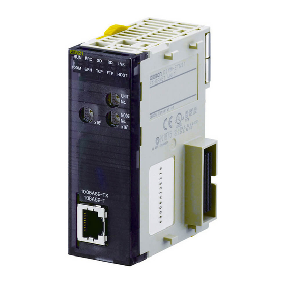
Omron SYSMAC CS1W-ETN21 Operation Manual
100base-tx ethernet units construction of networks
Hide thumbs
Also See for SYSMAC CS1W-ETN21:
- Operation manual (242 pages) ,
- Operation manual (289 pages)


Need help?
Do you have a question about the SYSMAC CS1W-ETN21 and is the answer not in the manual?
Questions and answers