
Related Manuals for Omron CJ1W-ETN21 - 04-2009


Summary of Contents for Omron CJ1W-ETN21 - 04-2009
- Page 1 Cat. No. W420-E1-06 SYSMAC CS and CJ Series CS1W-ETN21 (100Base-TX) CJ1W-ETN21 (100Base-TX) Ethernet Units Construction of Networks OPERATION MANUAL...
- Page 2 CS1W-ETN21 (100Base-TX) CJ1W-ETN21 (100Base-TX) Ethernet Units Construction of Networks Operation Manual Revised April 2009...
- Page 4 OMRON, 2003 All rights reserved. No part of this publication may be reproduced, stored in a retrieval system, or transmitted, in any form, or by any means, mechanical, electronic, photocopying, recording, or otherwise, without the prior written permission of OMRON.
- Page 5 Unit upgrades. Notation of Unit Versions The unit version is given to the right of the lot number on the nameplate of the on Products products for which unit versions are being managed, as shown below.
- Page 6 This label can be attached to the front of the Ethernet Unit to differentiate between Ethernet Units with different unit versions. Unit Version Notation In this manual, the unit version of a Ethernet Unit is given as shown in the fol- lowing table. Product nameplate...
- Page 7 viii...
-
Page 8: Table Of Contents
TABLE OF CONTENTS PRECAUTIONS ........ - Page 9 SECTION 8 Troubleshooting ........203 Troubleshooting with Indicators .
- Page 10 Revision History ........261...
- Page 12 Units (100Base-TX) and includes the sections described below. Please read this manual carefully and be sure you understand the information provided before attempting to install or operate the Ethernet Unit. Be sure to read the precautions provided in the fol- lowing section.
- Page 13 Relevant Manuals The following table lists CS and CJ-series manuals that contain information relevant to Ethernet Units. Manual Model Name Contents number CS1W-ETN21 Ethernet Units Oper- Provides information on operating and installing W420 CJ1W-ETN21 ation Manual 100Base-TX Ethernet Units, including details on basic Construction of Net- settings and FINS communications.
- Page 14 !WARNING Failure to read and understand the information provided in this manual may result in per- sonal injury or death, damage to the product, or product failure. Please read each section in its entirety and be sure you understand the information provided in the section and...
- Page 16 WHETHER SUCH CLAIM IS BASED ON CONTRACT, WARRANTY, NEGLIGENCE, OR STRICT LIABILITY. In no event shall the responsibility of OMRON for any act exceed the individual price of the product on which liability is asserted. IN NO EVENT SHALL OMRON BE RESPONSIBLE FOR WARRANTY, REPAIR, OR OTHER CLAIMS...
- Page 17 The following are some examples of applications for which particular attention must be given. This is not intended to be an exhaustive list of all possible uses of the products, nor is it intended to imply that the uses listed may be suitable for the products: •...
- Page 18 PERFORMANCE DATA Performance data given in this manual is provided as a guide for the user in determining suitability and does not constitute a warranty. It may represent the result of OMRON's test conditions, and the users must correlate it to actual application requirements.
- Page 20 Conformance to EC Directives ........
-
Page 21: Intended Audience
!WARNING It is extremely important that a PLC and all PLC Units be used for the speci- fied purpose and under the specified conditions, especially in applications that can directly or indirectly affect human life. You must consult with your OMRON representative before applying a PLC System to the above-mentioned appli- cations. -
Page 22: Operating Environment Precautions
• Emergency stop circuits, interlock circuits, limit circuits, and similar safety measures must be provided in external control circuits. !Caution Tighten the screws on the terminal block of the AC Power Supply Unit to the torque specified in the operation manual. The loose screws may result in burning or malfunction. - Page 23 Application Precautions • Always turn OFF the power supply to the CPU Unit, Slaves, and Commu- nications Units before attempting any of the following. Not turning OFF the power supply may result in malfunction or electric shock. • Mounting or dismounting I/O Units, CPU Units, Memory Packs, or Master Units.
-
Page 24: Conformance To Ec Directives
• Always lay communications cable inside ducts. • Use appropriate communications cables. • Before touching a Unit, be sure to first touch a grounded metallic object in order to discharge any static build-up. Not doing so may result in malfunc- tion or damage. - Page 25 Conformance to EC Directives Low Voltage Directive Always ensure that devices operating at voltages of 50 to 1,000 V AC and 75 to 1,500 V DC meet the required safety standards for the PLC (EN61131-2). xxvi...
-
Page 26: Features And System Configuration
Mail Send Function........ -
Page 27: Ethernet Unit Function Guide
Ethernet Unit Function Guide Section 1-1 Ethernet Unit Function Guide 1-1-1 Overall System Configuration Example The following diagram shows an example of an overall system configuration using Ethernet Units. (1) Connecting the CX-Programmer to the PLCs online via Ethernet CX-Programmer Mail software... - Page 28 (such as packet loss) resulting from unreliable connections. For CX-Programmer (version 4.0 or higher), FINS/TCP can be used to directly connect to the PLC online. To use lower versions of the CX- Programmer with FINS/TCP, use FinsGateway (version 2003 or higher) as personal computer middleware.
- Page 29 ETN01/ETN11 and CJ1W-ETN11). The protocol processing for FINS/UDP is simpler than for FINS/TCP, giving FINS/UDP certain advantages in terms of performance. Another feature of FINS/UDP is that it can be used for broad- casting. On the other hand, with FINS/UDP it is necessary to provide measures, such as retries, for handling communications errors.
- Page 30 • When a particular bit changes (either OFF to ON or ON to OFF) • When a change occurs at the Ethernet Unit (stored in error log) • When a change occurs at the CPU Unit (e.g., a non-fatal error, a fatal error, or a mode change) •...
- Page 31 Operation Use the mail receive function. When the mail receive function is used, the PLC can be accessed through a mail address, enabling remote applications via the Internet to be constructed relatively easily. With the mail receive function, any of the following remote commands can be specified as e-mail subjects.
- Page 32 Operation Use the FTP server function. The FTP server function makes it possible to log in to the Ethernet Unit from a computer (FTP client) as required, and to specify folders and files to be trans- ferred. The following items can be used as PLC File Memory.
-
Page 33: Features
PLC connected to the Ethernet Unit. The adjustment can be regularly executed at a specified time (once a day) and it can be executed each time by the ladder program. - Page 34 Transferring Data Files between Host Computers (FTP Server Function) A built-in FTP server function enables data files in the PLC to be read from a workstation or computer with an FTP client function, and for data to be written to the PLC.
- Page 35 Memory Card (up to 1 MB) to specified e-mail addresses as e-mail attachments. • In addition to using the existing Mail Send Switch, or having e-mail sent at regular intervals, it is possible to set triggers for sending e-mail (for exam-...
-
Page 36: System Configuration
System Configuration Section 1-3 Full Range of Functions for Handling Troubles A full range of functions is provided for promptly handling any troubles that may arise. • Self-diagnostic function when power is turned ON • Remote node connection check by PING command •... -
Page 37: Setup Area And Related Peripheral Devices
Setup Area and Related Peripheral Devices Making Settings in the For the Ethernet Unit to function as a node on an Ethernet network, make the CPU Bus Unit System settings, as required, in the CPU Bus Unit System Setup Area allocated in Setup Area (with the CX- non-volatile memory in the CPU Unit. - Page 38 When the CX-Programmer and CX-Integrator are connected online by FINS/ TCP, FinsGateway Version 2003 or higher must be used. For CX-Programmer Ver. 4.0 or higher, FINS/TCP can be used to directly con- nect to the PLC online. Personal computer running Windows...
-
Page 39: Specifications
Current consumption (Unit) 380 mA max. at 5 V DC Weight 200 g max. 35 × 130 × 101 mm (W × H × D) Dimensions Other general specifications Conform to general specifications for the SYSMAC CS Series. CJ-series Ethernet Unit... -
Page 40: Dimensions
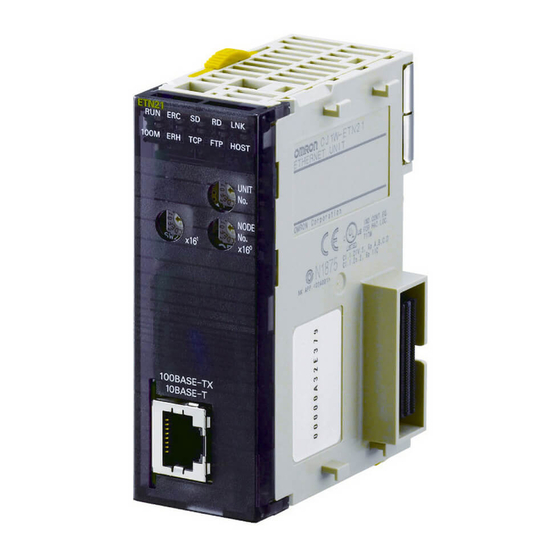
ETN21 100M HOST UNIT NODE ×16 ×16 100BASE-TX 10BASE-T (Unit: mm) CJ1W-ETN21 Back Front • Unit Version 1.5 or Later • Unit Version 1.4 or Earlier ETN21 ETN21 LINK LINK 100M FTP HOST 100M FTP HOST UNIT UNIT NODE NODE... -
Page 41: Software Configuration
Section 1-4 Specifications 1-4-3 Software Configuration The software supported by the Ethernet Unit runs in the layers shown in the following diagram. The components that form the various layers are defined below the diagram. Memory Card / CS/CJ-series CPU Unit... -
Page 42: Overview Of Communications Functions
1-5-1 FINS Communications Service Basic Functions FINS commands can be sent to or received from other PLCs or computers on the same Ethernet network by executing SEND(090), RECV(098), or CMND(490) instructions in the ladder diagram program. This enables various control operations such as the reading and writing of I/O memory between PLCs, mode changes, and file memory operations. -
Page 43: Socket Services
Section 1-5 Overview of Communications Functions • Even if the IP address and UDP port number of the host computer (a DHCP client computer) are changed, it is still possible for the host com- puter to send FINS commands to PLCs on the Ethernet network and to receive responses. - Page 44 Overview of Communications Functions Executing CMND(490) Another way to use socket services is to request a UDP or TCP socket ser- vice by sending a FINS command to the Ethernet Unit by executing CMND(490) from the CPU Unit. When the Ethernet Unit receives the socket service request, it returns a response to the CPU Unit to confirm that it received the request, and then begins the requested processing.
-
Page 45: Ftp Server Function
Memory Card) as an e-mail attachment from the Ethernet Unit to speci- fied e-mail addresses when a pre-specified PLC condition is met. User-cre- ated data (in ASCII), error log data, and status data in the CPU Unit can all be sent as text. -
Page 46: Mail Receive Function
(3) Mail server settings require specialized knowledge, so they should al- ways be handled by the network administrator. (4) Be sure that you have a clear understanding of the mail system before us- ing this function. (5) Mail my not always be delivered. Depending on factors such as the con- dition of the network, mail that has been sent may not arrive at its desti- nation. -
Page 47: Automatic Clock Adjustment Function
The Ethernet Unit can acquire clock information from the SNTP server at a particular time or when a dedicated bit turns ON, and it can refresh the inter- nal clock information of the CPU Unit to which it is mounted. -
Page 48: Nomenclature And Functions
Used to connect the Ethernet twisted-pair cable. Each communications device connected to the Ethernet network is allocated a unique Ethernet address. For the Ethernet Unit, this Ethernet address is shown on the right side of the Unit as a 12-digit hexadecimal number. CS1W-ETN21 ETHERNET UNIT Lot No. - Page 49 An IP address label is provided with the Unit. Writing the IP address and the subnet mask on this label and then attaching it to the front of the Unit allows the IP address and subnet mask to be easily confirmed.
-
Page 50: Indicators
The Ethernet address can also be checked using the FINS command, CON- TROLLER DATA READ. For details, refer to 7-3-2 CONTROLLER DATA READ on page 162. 1-6-2 Indicators The status of the indicators show the operating status of the Ethernet Unit, as shown below. CS1W-ETN21 CJ1W-ETN21 (100Base-TX) - Page 51 CPU Unit normal (CPU Unit error) An error has occurred at the CPU Unit. There is an error in the I/O table, unit number, unit setup, or routing table settings. Flashing An illegal IP address has been set. With automatic address gener- ation, the rightmost two digits of the IP address do not match the node address.
-
Page 52: Comparison With Previous Models
TCP socket services function: • Use of keep-alive • Number of bytes of data received for TCP socket Nos. 1 to 8 • Status of TCP socket Nos. 1 to 8: Data Received Flag Automatic clock information Not possible... -
Page 53: Unit Version Upgrade Information
Section 1-8 Unit Version Upgrade Information Unit Version Upgrade Information The details of the upgrade to the Ethernet Unit version are as follows: ■ Unit Version 1.3 Upgrade Details Web function added The unit settings and status monitoring for the Ethernet Unit can be easily performed from a Web browser. -
Page 54: Installation And Initial Setup
Overview of Startup Procedure ........ -
Page 55: Overview Of Startup Procedure
Note 1: Used mainly when a Programming Console is used to set only the local IP address (set in allocated DM words). When using this method, always leave the local IP address in the CPU Bus Unit Setup Area set to the default value of 0.0.0.0 If the CPU Bus Unit Setup Area contains any other value, any setting made in the allocated DM words will be overwritten with it. -
Page 56: Switch Settings
Note (1) Turn OFF the power supply before setting the unit number. (2) If the unit number is being set for the first time or changed, then I/O tables must be created for the PLC. (3) With CS-series and CJ-series PLCs, words are automatically allocated in the CIO Area and DM Area according to the unit numbers that are set. -
Page 57: Cj-Series Ethernet Units
Note (1) Turn OFF the power supply before setting the unit number. (2) If the unit number is being set for the first time or changed, then I/O tables must be created for the PLC. (3) With CS-series and CJ-series PLCs, dedicated areas are automatically allocated in the CIO Area and DM Area according to the unit numbers that are set. -
Page 58: Mounting To A Plc
Expansion CPU Rack. Connect the Ethernet Unit in any of the posi- tions shown below using the sliders on the top and bottom of the Unit. Up to four Ethernet Units can be mounted to a single PLC. If it is mounted in combi- nation with other CPU Bus Units (e.g., Controller Link Units), the maximum... -
Page 59: Network Installation
II: I/O Interface Unit The CJ1W-ETN21 Ethernet Unit’s maximum current consumption is 370 mA. Make sure that the total current consumption of all the Units connected to the same CPU Backplane or Expansion Backplane does not exceed the output capacity of the Power Supply Unit. -
Page 60: Recommended Products
Precautions Precautions on Laying Twisted-pair Cable Basic Precautions • Press the cable connector in firmly until it locks into place at both the hub and the Ethernet Unit. • After laying the twisted-pair cable, check the connection with a 10Base-T cable tester. - Page 61 • Connect the hubs using special cables or special racks. • Normally there is no limit to the number of hubs in a stack, and each stack is treated as one hub. Some hubs, however, are limited in the number of hubs per stack.
-
Page 62: Using Contact Outputs (Common To All Units)
Using Contact Outputs (Common to All Units) Communications errors can occur when Contact Output Units are mounted to the same Rack or connected to the same PLC as an Ethernet Unit due to noise generated by the contact outputs. Use one or more of the following measures when installing Contact Output Units and Ethernet Units on the same Rack. -
Page 63: Connecting To The Network
!Caution Allow enough space for the bending radius of the twisted-pair cable as shown in below. 35 mm 1,2,3... 1. Lay the twisted-pair cable. 2. Connect the cable to the hub. Be sure to press in the cable until it locks into place. Request cable installation from a qualified professional. -
Page 64: Creating I/O Tables
2-6-1 I/O Table Overview I/O tables are used to identify Units mounted to the PLC, and to allocate I/O to them. With CS-series and CJ-series PLCs, whenever there is a change to the Unit configuration it is necessary to create I/O tables and register the Units to the CPU Unit. -
Page 65: Procedure For Creating I/O Tables
Use the following procedure to create the I/O tables. Note With the CJ Series, it is necessary to create I/O tables only when I/O alloca- tion is performed by the user. With the CS Series, it is always necessary to create I/O tables. -
Page 66: Unit Setup Procedure
Connect the personal computer to the PLC by serial cable, through ei- ther a peripheral port or RS-232C port. b. Connect the personal computer to the PLC by Ethernet. When Ethernet Unit is registered in the I/O tables in the CPU Unit, the Ethernet Unit... - Page 67 Unit Setup Procedure Section 2-7 3. Read the I/O tables from the PLC and select the Rack to which the Ether- net Unit is mounted. 4. Move the cursor to the Ethernet Unit and right-click. Select Unit Setup from the popup menu to display the window for making the Ethernet Unit Setup.
-
Page 68: Using The Web Browser Setting Function
6. Transfer the settings to the PLC. Click on Yes in the following dialog box. In order for the Ethernet Unit Setup to go into effect, the Unit must be re- started. Click on Yes in the following dialog box. - Page 69 1. Connect to the Ethernet Unit from the Web browser. In this example, the URL is specified as http://192.168.250.1/0 using the Ethernet Unit’s default IP address. 2. Select Settings from the menu on the left side of the window to display the Settings Menu.
- Page 70 Section 2-7 Unit Setup Procedure 3. Select 1. IP address and Protocols - System to display the Login Pass- word field on the right of the window. 4. Input the default password (“ETHERNET” all in upper case) and click the Login Button.
-
Page 71: Basic Settings
Basic Settings 6. Make the required settings (i.e., the IP address in this example). 7. After entering the correct values, click the Set Button followed by the Reg- ist Button to register them. The Set Button is used to transfer the entered values from the personal com- puter, and temporarily register them in the Ethernet Unit. - Page 72 CPU Bus Unit Words Allocated in the DM Area, when the IP address is not set in the Unit Setup. When the IP address is set in the Unit Setup, the IP Address Display/Setting Area becomes the area for displaying the settings.
- Page 73 Example: Using the CX-Programmer to Set the IP Address to 10.3.65.1 When an IP address is set in the Unit Setup, that value is displayed in the IP Address Display/Setting Area in the DM Area words allocated for CPU Bus Units.
- Page 74 If CIDR is not enabled and a subnet mask is not set (i.e., the default of 0.0.0.0 is set) or an illegal value is set, one of the following values will be set as the network mask according to the class of the local IP address.
-
Page 75: Unit Setup For Particular Applications
A maximum of eight settings can be registered. The default is for nothing to be set. Settings In this example setting for Node A (refer to the diagram above), a node with an IP address of 130.26.1.1 is connected to an IP router with an IP address of 130.25.36.253. - Page 76 Setting Setup Keep-alive CX-Programmer tab Settings Setup Login Password Port No For details, refer to SECTION 4 FTP Server Function in the Operation Manual Construction of Applications. Mail CX-Programmer tab Settings IP Address Port No. Retry timer SMTP Server specification type...
-
Page 77: Communications Test
For details, refer to Appendix G Ethernet Unit Web Function. 2-10 Communications Test If the basic settings (in particular the IP address and subnet mask) have been made correctly for the Ethernet Unit, then it should be possible to communi- cate with nodes on the Ethernet. -
Page 78: Ethernet Unit
Method Input the following at the host computer prompt ($): $ ping IP_address(host_name) The destination is specified by its IP address or host name. If the host name is used, the host name must be defined in file /etc/hosts. Note The PING command is not supported by some host computers. -
Page 79: Converting From Previous Models
Unit is simply replaced. In particular, the CPU Bus Unit System Setup Area is formatted for the previ- ous models, so there is no way to make the settings for the expanded specifi- cations. To remove these limitations, it is necessary to change the CPU Bus Unit Sys- tem Setup format from “ETN11 mode”... - Page 80 (1) These limitations do not apply when the CPU Bus Unit System Setup Area format is in ETN21 mode. (2) When I/O tables are created using one of the new Ethernet Unit models, the CPU Bus Unit System Setup Area format is in ETN21 mode from the beginning.
- Page 81 Section 2-11 Converting from Previous Models Checking with the CX-Programmer's Unit Setup Window ■ Window Display in ETN21 Mode ■ Window Display in ETN11 Mode ■ Checking by Reading Words Allocated in the CIO Area n+17 System Setting Format...
- Page 82 Other Reserved Changing the CPU Bus The CPU Bus Unit System Setup Area format can be changed in either of the Unit System Setup Area following two ways. Select the method that can be used in the system in which Format the Unit is to be replaced.
- Page 83 2. Turn ON the power to the PLC. The Unit's indicators will change as follows: Node address Indicators ×16 ×16 Not lit Not lit 3. Set the rotary switches for the node address to 01. There will be no change to the indicators. Node address Indicators ×6 ×16 Not lit Not lit 4.
- Page 84 2. Turn ON the power to the PLC. The Unit's indicators will change as follows: Node address Indicators ×16 ×16 Not lit Not lit 3. Set the rotary switches for the node address to 0F. There will be no change to the indicators. Node address Indicators ×16 ×16 Not lit Not lit 4.
- Page 85 I/O tables, and correct the settings using the procedures described in this section. 7. Turn OFF the power to the PLC and return the Ethernet Unit's rotary switches for the node address to its original setting. 8. Turn ON the power to the PLC.
-
Page 86: Cx-Programmer Unit Setup
Auto Adjust Time ........ -
Page 87: Setup
192.168.250.) Sub-net Mask Set the subnet mask for the Ethernet Unit. 0.0.0.0 This is required if a method other than the IP address table method is (default subnet used for address conversion. mask for IP address setting) Enable CIDR Set the specifications for the subnet mask. - Page 88 (Number 21 is used.) Two ports are used for FTP: a control port and a data transfer port. This setting sets only the control port, and then the data transfer port uses the number that is one less than the control port.
-
Page 89: Fins/Tcp
TCP is used for the FINS communica- tions service. It corresponds to a socket in the socket services. Up to 16 can be used at a time, and they are identified by connection numbers 1 to 16. The... - Page 90 Default FINS/TCP Mode For each connection number, this setting specifies Server the Ethernet Unit for use as either a server or a cli- ent. • When the Ethernet Unit is used as a server: The Ethernet Unit opens a connection with that connection number and waits for service requests (FINS commands) from clients.
-
Page 91: Dns
(Number 53 is used.) This setting does not normally need to be changed. Retry Timer Set the time to elapse before retrying when a connec- 0 (10 s) tion to the DNS server fails. This setting does not normally need to be changed. -
Page 92: Smtp
(POP before SMTP) in which the POP server must be accessed (to receive mail) before the SMTP server is accessed (to send mail). For details, refer to SECTION 2 Mail Send Function in the Operation Manual Construction of Applications. -
Page 93: Pop
Set the interval for sending and receiving mail. Mail Interval will be automatically sent and received at the inter- (5 minutes) val set here. For details, refer to SECTION 3 Mail Receive Function in the Operation Man- ual Construction of Applications. -
Page 94: Mail Address
Destination Mail Address Setup Item Contents Default Mail Address 1 Set one of the addresses to which the Ethernet Unit None is to send mail. (Up to two address can be set.) Note: Mail can be sent to multiple addresses by punctuating the mail address with commas. -
Page 95: Send Mail
Item Contents Default Send Trigger Select a number as the trigger condition for send- ing mail. Up to eight trigger numbers can be regis- tered. Use send trigger Sets whether or not the selected mail trigger is to Not checked... - Page 96 Checked trigger ware Mail Send Switch turns ON. type switch The Mail Send Switch is bit 03 of word n in the (Select words allocated for CPU Bus Units. (n = 1500 + 25 only x unit number) one.) Word...
-
Page 97: Receive Mail
1 to 1,000 (1 to 1,000 s), in units as the mail trig- of 1 s ger type Default: 0000 For details, refer to SECTION 2 Mail Send Function in the Operation Manual Construction of Applications. Receive Mail Posting Mail Address Protection Setting Item... - Page 98 Use the checkboxes below to select which file extensions are to be accepted. Multiple exten- sions can be selected. If this option is selected, an OBJ file (which can Checked be created using the CX-Programmer) contain- ing all cyclic task and interrupt task programs in the CPU Unit will be received.
-
Page 99: Auto Adjust Time
Auto Adjust Time Section 3-9 For details, refer to SECTION 3 Mail Receive Function in the Operation Man- ual Construction of Applications. Auto Adjust Time SNTP Server Setup Item Contents Default Obtain clock If this option is selected, the CPU Unit's clock is set to data from SNTP the time at the SNTP server's clock. -
Page 100: Http
Web browser. For details, refer to Appendix G Ethernet Unit Web Function. Note (1) The HTTP Server Setup is supported by Ethernet Units with Unit Ver. 1.3 or later. (2) Make settings using the unit settings function in the CX-Programmer (to be included in version 5.0 and higher) or using the Web function (refer to... - Page 101 Section 3-10 HTTP...
-
Page 102: Ethernet Unit Memory Allocations
CIO Area Allocations ........ -
Page 103: Cio Area Allocations
CIO Area Allocations CIO Area Allocations The various kinds of data are stored in the offset positions shown in the fol- lowing diagram, from the beginning word in the area for each Unit. The beginning word n is calculated by the following equation: Beginning word n = CIO 1500 + (25 ×... - Page 104 Section 4-1 CIO Area Allocations Unit Control Bits (CPU Unit to Ethernet Unit) 15 14 13 12 11 10 09 08 07 06 05 04 03 02 01 00 Socket Force-close Switch Mail Send Switch Automatic Clock Adjustment Switch Switch...
- Page 105 Section 4-1 CIO Area Allocations Status of UDP/TCP Sockets 1 to 8 (Ethernet Unit to CPU Unit) 15 14 13 12 11 10 09 08 07 06 05 04 03 02 01 00 n+1 to n+16 Data Received Flag Opening Flag...
- Page 106 CMND(490) instruction, and turns OFF again when the close process- ing has been completed. When CMND(490) is used, the Results Storage Error Flag (bit 14) will turn ON at the same time as the Closing Flag turns OFF if there is an error in the Results Storage Area designation.
- Page 107 Check to be sure that this flag is ON before executing a send or receive request. Service Status (Ethernet Unit to CPU Unit) 15 14 13 12 11 10 09 08 07 06 05 04 03 02 01 00 n+17 FTP Status...
- Page 108 CIO Area Allocations Accessing Memory (Sending Mail) (Bit 01) This bit turns ON while CPU Unit memory is being accessed to create a file to be attached using the mail send function, and it turns OFF when the file has been created.
- Page 109 OFF when the EEPROM memory is normal. Socket Service Request When a socket service request is executed by control bit manipulation, it is the Switches 1 to 8 (CPU Unit following bits that are manipulated. For details, refer to Operation Manual, to Ethernet Unit) Construction of Applications, SECTION 6.
- Page 110 (The protocol (TCP/UDP) is determined when the socket is opened.) Unit Unit turns OFF switch when close processing has been completed. (Not used.) (Not used.) FINS/TCP Connection Status 15 14 13 12 11 10 09 08 07 06 05 04 03 02 01 00 n+23...
-
Page 111: Dm Area Allocations
DM Area Allocations The various kinds of data are stored in the offset positions shown in the fol- lowing diagram, from the beginning word in the area for each Unit. The beginning word m is calculated by the following equation:... - Page 112 While mail is being sent, the transmission status of the three bits each for send condition settings 1 to 8, i.e., bits 02, 01, and 00; bits 06, 05, and 04; or bits 10, 09, an 08 are 0, 0, and 1 respectively. After the transmission has been completed normally, they become 0, 1, and 0.
- Page 113 DM Area Allocations TCP Socket No. (1 to 8): Number of Bytes Received (Ethernet Unit to CPU Unit) 15 14 13 12 11 10 09 08 07 06 05 04 03 02 01 00 m+1 to m+8 Number of Bytes Received (0000 to 07C0 hex) For each TCP socket, the number of bytes of data in the reception buffer is stored in one word.
- Page 114 IP address: (1)(2).(3)(4).(5)(6).(7)(8) (Hex) If the local IP address in the CPU Bus Unit System Setup is set to a value other than 0.0.0.0, this area (words m+98 and m+99) will act as an IP Address Display Area and the local IP address set in the CPU Bus Unit System Setup will be read and stored here when the power is turned ON or the Unit restarted.
-
Page 115: Auxiliary Area Data
Section 4-3 Auxiliary Area Data Auxiliary Area Data The following table and descriptions cover the words and bits in the Auxiliary Area of PLC memory that are related to the Ethernet Unit. Read-only Bits/Words Word(s) Bit(s) Name Function Settings A202 A202.00 to... - Page 116 When an error occurs in a data exchange between 0: No error A417.15 Unit Number Flags the CPU Unit and a CPU Bus Unit, the CPU Bus 1: Error Unit Error Flag (A402.07) and the corresponding flag in A417 are turned ON. Bits 00 to 15 corre- spond to unit numbers 0 to F.
- Page 117 Section 4-3 Auxiliary Area Data...
-
Page 118: Determining Ip Addresses
Private and Global Addresses ........ -
Page 119: Ip Addresses
5-1-1 IP Address Configuration IP addresses are made up of 32 bits of binary data divided into four 8-bit fields called octets. These four octets provide the network number (net ID) and host number (host ID). The network number identifies the network, and the host number identifies the node (or host) on the network. -
Page 120: Ethernet Unit Ip Address Settings
ID and a host ID by using a setting called the subnet mask. The subnet mask indicates which part of the host ID is to be used as the subnet ID. All bits in the subnet mask that correspond to the bits in the IP address used either as the network ID or subnet ID are set to “1,”... -
Page 121: Ip Addresses In Fins Communications
Physical level Ethernet Ethernet address Note Use the “Node No.” rotary switch on the front of the Ethernet Unit to set the FINS node address. Allocating Addresses to Ethernet Units Ethernet Unit FINS The IP address, FINS/UDP port number, and FINS/TCP port number set for... - Page 122 Pairing IP Addresses with A particular IP address is allocated to each communications node, including FINS Node Addresses at Ethernet Units. The IP address must be paired with the FINS node address (1 Local Nodes to 254) by one of the following methods.
-
Page 123: Pairing Addresses In Internal Tables
With the dynamic method, data in an internal table that has been generated can be dynamically converted according to FINS messages received from remote nodes. This is enabled when the remote node is a device such as a personal computer and IP addresses are dynamically changed by a method such as DHCP. - Page 124 FINS node address • Remote UDP port number: UDP port number set for local Unit • Connection method: FINS/UDP With the static method, however, data in an internal table that has been gener- ated is not freely changed. Ethernet Unit CPU Unit...
- Page 125 Unit is turned ON or restarted, according to FINS messages received from remote nodes. This can be used effectively when the remote node is a device such as a personal computer and IP addresses are dynamically changed by a method such as DHCP.
- Page 126 FINS response returned Note When an internal table IP address has been changed with the reception of a FINS command, this is sent to the IP address in the internal table. Prohibiting Dynamically Changing Remote IP Addresses For Ethernet Units with Unit Ver. 1.3 or later, methods used to dynamically change remote IP addresses (automatic generation, IP address table, or com- bined (mixed) method) can be prohibited (protected against).
- Page 127 • If the command data is for the Ethernet Unit, a FINS response will be sent to the source UDP port number. • If the command data is for any other Unit, such as the CPU Unit, a FINS response will be sent to the UDP port number set as the FINS/UDP port number.
- Page 128 1. Connections are established in TCP/IP protocol with the IP addresses set at the Unit (i.e., the IP address for each connection No.). 2. The remote node (i.e., the server) is notified of the FINS node address for the local device.
- Page 129 2. Set the IP addresses for the connection destination. Set the IP address for the remote Ethernet Unit (i.e., the server) connected by FINS/TCP. This setting must be made if this Ethernet Unit is to be used as a FINS/ TCP client.
-
Page 130: Application Examples
FINS messages are received. Therefore, even when a FINS command has been received from a personal computer (a DHCP client computer) for which the IP address is dynamically changed, a response can still be sent back to the computer (the DHCP client computer) from which the command origi- nated. -
Page 131: Related Products And Communications/Setting Methods
In communications involving previous models, multiple communications appli- cations were configured on personal computers according to data accessing uses, and the fact that no more than one UDP port number for FINS commu- nications could be used on any given computer created a problem. This... - Page 132 Programmable Terminal NS Series No: Set manually. FINS communications are not Open Network Controller (ONC) possible with personal computers set automati- cally by DHCP. Models that Can Use the Combined Method Product Model/Series/ Supports combined Version method? CS-series Ethernet 100BASE-TX...
-
Page 133: Private And Global Addresses
DHCP. 5-2-5 Pairing IP Addresses and FINS Node Addresses The following table shows the methods for pairing IP address and FINS node addresses, and the relation between fixed and variable address, for both FINS/UDP and FINS/TCP. Communi-... - Page 134 Internet. Addresses for Ethernet • FINS communications services Units • File transfers • Socket services When mail is sent or received over the Internet, the Unit's IP address can be a private address.
-
Page 135: Using A Private Address For The Ethernet Unit
• FINS communications service is enabled only between Ethernet Units with private addresses on the intranet. A device such as a personal computer (with a FINS application including a CX-Programmer) cannot connect online and communicate over the Internet with an Ethernet Unit that has a private address. FINS communi- cations over the Internet are also not possible between Ethernet Units with private addresses. - Page 136 (i.e., an FTP client) with a private address on the intranet. • The TCP port number to be used for FTP cannot be used if prohibited by a firewall in the communications path. 3. Sending Mail The PLC can send the Ethernet Unit's IP address to the SMTP server by mail via the intranet.
-
Page 137: Ethernet Unit With A Global Address
(i.e., an FTP client) and a PLC with an Ethernet Unit that has a global address. • The TCP port number to be used for FTP cannot be used if prohibited by a firewall in the communications path. - Page 138 • The PLC can send the Ethernet Unit's IP address to the SMTP server by mail via the intranet, even if it as a private address. • The TCP port number (default: 25) to be used for SMTP cannot be used if prohibited by a firewall in the communications path. Also, with some com- munications companies, there may be restrictions, based on mail security considerations, on using POP before SMTP.
- Page 139 Private and Global Addresses Section 5-3...
-
Page 140: Fins Communications
Writing Programs ........ -
Page 141: Overview Of Fins Communications
FINS node address for FINS (the application layer) are used for the remote device. Also, 9600 is used as the default setting for the local UDP or TCP port number (i.e., the transport layer) for identifying the application layer, i.e., the FINS communications service. -
Page 142: Fins Communications Service Specifications For Ethernet
Protocol name FINS/UDP method FINS/TCP method Protocol used UDP/IP TCP/IP The selection of UDP/IP or TCP/IP is made by means of the FINS/TCP Tab in the CX-Pro- grammer's Unit Setup. Number of connections --- Port number 9600 (default) 9600 (default) Can be changed. -
Page 143: Fins/Udp Method
IP protocol. UDP/IP is a connectionless communications protocol. When a message is sent from one node to another, the two nodes have an equal rela- tionship and there is no clear connection. If using TCP is like making a tele- phone call, then UDP is more like delivering a memo by hand. - Page 144 ↓ Make the settings in the Unit Setup. With the CX-Programmer connected online, select the Ethernet Unit in the CX-Programmer's I/O Table Window. Right-click, and select Unit Setup. Then make the following settings in the Unit Setup Window. Setup Tab •...
-
Page 145: Fins/Tcp Method
• TCP/IP has various retry procedures, and this tends to lower its perfor- mance in comparison with UDP/IP. • There is a limit to the number of connections that can be made (i.e., 16 connections maximum), and any given node can communicate only with... - Page 146 TCP data sections from multiple packets are all joined together. Therefore, when using the FINS/TCP method, FINS/TCP headers must be added at the beginning of FINS frames in order to serve as FINS frame delimiters. The length of the data in the following FINS frame is stored in the header, allowing the frame to be separated out by the remote node.
- Page 147 FINS/TCP connection status turns ON in the section of the CPU Bus Unit words allocated in the CIO Area. The bit turns OFF if the connection is termi- nated by a communications error or a FINS command (i.e., FINS/TCP CON- NECTION REMOTE NODE CHANGE REQUEST).
- Page 148 FINS/TCP server every few seconds to open a connection. Note After the Ethernet Unit is powered up or restarted, the IP address for the con- nection used as the FINS/TCP client is the remote IP address set under the FINS/TCP Tab in the Unit Setup.
-
Page 149: Creating Routing Tables
Network #4 Note 1. The unit number is set (0 to F: 1 to 15) by the rotary switch on the front of the Ethernet Unit. 2. The network address is the number of the network (1 to 127) to which the Communications Unit or Board is connected. -
Page 150: Connecting And Using A Peripheral Device For The Plc
In the above example, the routing tables required for a message to reach PLC #4 from PLC #1 are shown. Additional settings would be required in the rout- ing tables for a message to reach PLC #1 from PLC #4. Refer to 6-4-3 Rout- ing Table Setting Examples for routing table setting examples. -
Page 151: Routing Table Setting Examples
PLC #5 Node #g In the table for PLC #3, for example, if network #A is taken as the end net- work, then network #B becomes the relay network and node #c becomes the relay node. If network #C is taken as the end network, then network #B still... - Page 152 Creating Routing Tables Section 6-4 ■ Example 3: All Nodes This example uses the following configuration to show the routing tables for all nodes. Unit #5 Node #6 Network #10 Unit #4 Unit #3 Node #5 Node #4 Unit #7...
-
Page 153: Using Fins Applications
■ System Configuration Example 1: No Routing In this example, an online connection is made by FINS/UDP to a PLC on an Ethernet network (PLC1 in the diagram below) from a CX-Programmer or CX- Integrator connected to the Ethernet network. - Page 154 FINS/UDP port Default (9600) IP address 0.0.0.0 (Use default IP address.) Subnet mask 0.0.0.0 IP address conversion Automatic generation method (dynamic) Baud rate Automatic detection IP router table None Example: Inputs to the CX-Programmer's Setup Window Example: Change PLC Settings...
- Page 155 Section 6-5 Using FINS Applications Example: Network Settings (Network Tab) Note When FinsGateway is selected as the network type, make sure that the frame length is set to 2,000 bytes max. Example: Network Settings (Driver Tab)
- Page 156 ■ System Configuration Example 2: Using Routing Tables In this example, an online connection is made via the Ethernet to a PLC on a Controller Link network (PLC 3 below) from a CX-Programmer or CX-Integra- tor connected to the Ethernet network.
-
Page 157: Finsgateway
Unit number Local network number • Relay Network Table In order to relay from PLC2/3 to the final network number 1, it is necessary to relay via node address 1 (i.e., the Controller Link Unit) on relay network number 2. - Page 158 Set the personal computer (Ethernet port) node address (1 to 254) on the Ethernet network. • Communication unit number Set the unit number in decimal (16 to 31) for the per- sonal computer (Ethernet port). • Communication Unit Tab • UDP port number Set the local UDP port number for the personal com- puter (Ethernet port).
- Page 159 • UDP Nodes Tab: Automatic Generation Method (Dynamic or Passive) • UDP Nodes Tab: IP Address Table Method or Combined Method Click the Add Button, and then set the IP address table in the following Ether- net Node Definition Dialog Box.
- Page 160 • Node address: Set the remote FINS node address. • IP address: Set the remote IP address. • TCP Nodes Tab Click the Add Button, and then set the IP address table in the following Ether- net Node Definition Dialog Box.
- Page 161 System Configuration Example 3: Connecting the CX-Programmer Online Using the FINS/TCP Method In this example, an online connection is made by FINS/TCP to a PLC on an Ethernet network (PLC1 in the diagram below) from a CX-Programmer/CX- Integrator connected to the Ethernet network.
-
Page 162: Communicating Between Omron Plcs
RECV(098): Reads I/O data from another node to the local node. CMND(490): Issues FINS commands for controlling operations such as send- ing and receiving I/O memory data to and from other nodes, reading informa- tion regarding other nodes, and so on. -
Page 163: Plc Communications Data Areas
1. Data cannot be written to words A000 to A447 in the Auxiliary Area. 2. A maximum of 13 banks in the EM Area can be used. For details regarding the EM Area, refer to the operation manual for the PLC that is used. -
Page 164: Using Send(090), Recv(098), And Cmnd
SEND(090) The SEND(090) instruction sends the data in n number of words, starting from the beginning word S at the local node, to the words starting from the begin- ning word D at the remote destination node (node address N). - Page 165 RECV(098) With the RECV(098) instruction, the data in m number of words, starting from the beginning word S at the remote node (node address M) is received at the words starting from the beginning word D at the local node.
- Page 166 The CMND(490) instruction sends n bytes of command data, starting from the beginning word S at the local node, to the node at node address N. the data in m number of words, starting from the beginning word S at the remote node (node address M) is received at the words starting from the beginning word D at the local node.
- Page 167 Section 6-6 Commands Addressed to CS/CJ-series CPU Units The following table provides a list of FINS commands that can be processed by a CS/CJ-series CPU Unit. For details, refer to the CS/CJ-series Program- mable Controllers Communications Commands Reference Manual (W342).
-
Page 168: Writing Programs
CPU Units have eight communications ports. Only one instruction can be executed at any given port at one time, however, so the program must not overlap the use of any of the ports. A program example is provided below. - Page 169 Bit 1: Port 1 Bit 0: Port 0 Note With CS/CJ-series PLCs, communications ports 0 to 7 are also used for exe- cuting the PCMR(260) (PROTOCOL MACRO) instruction, so these flags are used in common for SEND(090), RECV(098), CMND(490), and PCMR(260).
- Page 170 Completion Codes execution is reflected as a communications port completion code, in one word (two bytes) of data as shown in the following table. (The value is 0000 during instruction execution.) The recorded status is saved until execution of the next instruction.
- Page 171 Section 6-6 Communicating between OMRON PLCs Example Communications Port Enabled Flag Communications instruction: Instruction 3 Instruction 1 Instruction 2 being executed. being executed. SEND(090), RECV(098), CMND(490) being executed. Communications Port Error Flag 0000 0000 0000 Communications Port Completion Code Completion...
-
Page 172: Program Example
Ten words of data from word CIO 0000 is #000A stored from D00010 onwards. 0000 D00010 @SEND(90) Ten words of data from D00010 at the local node is D00010 sent to D00020 onwards at network number 2, node number 4, unit address 0 (the PLC). D00020 D00000 (See note.) - Page 173 Note 1. With CS/CJ-series PLCs, the Communications Port Enabled Flags at bits 0 to 7 in word A202 turn OFF even when the PCMR(260) instruction is be- ing executed using the ports corresponding to those flags. 2. Before using the sample program as is, confirm that the memory areas (words and bits) used in the sample program are not already being used in the user program o r by Special I/O Units.
-
Page 174: Transmission Delays
Section 6-6 Communicating between OMRON PLCs 6-6-6 Transmission Delays The methods of computing the maximum time required from execution of the SEND(090), RECV(098), and CMND(490) instructions until processing is completed are described in this section. SEND(090) The transmission delay for the SEND(090) instruction can be calculated using the following equation, which is illustrated in the following diagram. - Page 175 Number of words sent x 0.002 + 0.550 ms Transmission Delay The transmission delay time will be as given below, depending on the baud rate set for the Ethernet Unit. (There may be additional delays depending on devices, such as hubs, in the network configuration.)
- Page 176 256 × 0.003 + 0.704 = 1.472 ≈ 1.5 ms Reception processing time CPU Bus Unit service cycle (remote node) 5 ms CPU Bus Unit service processing time 0.2 ms (remote node) Total 10 + 0.4 + 1.1 + 0.3 + 1.5 + 5 + 0.2 = 18.5 ms...
- Page 177 + CPU Bus Unit Service Cycle (local node 2) + CPU Bus Unit service processing time (local node CPU Bus Unit Service Cycle (Local Node 1) The processing time will be as follows, depending on the CPU processing mode settings at the CPU Unit: CPU processing mode...
- Page 178 Number of words sent × 0.002 + 0.550 ms Response Transmission Delay (Command) The transmission delay time will be as follows, depending on the baud rate set for the Ethernet Unit. (There may be additional delays depending on devices such as hubs in the network configuration.)
- Page 179 Section 6-6 Communicating between OMRON PLCs CPU Bus Unit service processing time (remote node) The processing time will be as follows, depending on the CPU processing mode settings at the CPU Unit. CPU processing mode Processing time considerations settings Normal Mode...
-
Page 180: Precautions On High Traffic In Fins Communications
CPU Bus Unit service processing time (local node 2) 0.4 ms Total 10 + 0.4 + 0.5 + 0.1 + 0.7 + 15 + 0.6 + 1.1 + 0.3 + 1.5 + 10 + 0.4 = 40.6 ms Precautions on High Traffic in FINS Communications... - Page 181 2 seconds to send a response to the last command. If a time- out is set at the remote node for 2 seconds or less, then a timeout will be gen- erated. A retry will begin due to the timeout, and the traffic to the Ethernet Unit will thus be increased even further, until ultimately the responses to all the nodes will be too slow.
-
Page 182: Fins Commands Addressed To Ethernet Units
Command Code List ........ -
Page 183: Command Codes And Response Codes
Section 7-1 Command Codes and Response Codes Command Codes and Response Codes 7-1-1 Command Code List The command codes listed in the following table can be sent to an Ethernet Unit. Command code Name Page RESET CONTROLLER DATA READ CONTROLLER STATUS READ... -
Page 184: Socket Applications
Specifies the requested process. Socket Option For the TCP OPEN REQUEST (ACTIVE or PASSIVE), specifies whether or not the keep-alive function is to be used. For all other commands it is dis- abled. (Set to 0). Socket Number Specifies the socket number for which the process is requested, from 1 to 8. -
Page 185: Plc Memory Areas
The memory areas of the PLC that can be specified for results storage when executing commands from the PC are listed in the table below. The Variable type is set in the first byte of the results storage area. The remaining three bytes contain the address for communications. -
Page 186: Command/Response Reference
If the data is fixed, it is included in the blocks. If the data is variable, it is described following the blocks. Each box represents 1 byte; every two boxes represents 1 word. -
Page 187: Controller Data Read
Model, Version The Ethernet Unit mode and version are returned as ASCII characters occu- (Response) pying 20 bytes each (i.e., 20 characters each). If all bytes are not used, the remaining bytes will be all spaces (ASCII 20 Hex). Example Model:... -
Page 188: Controller Status Read
ETN21 mode Other Reserved Ethernet Address The Ethernet address of the Ethernet Unit is returned. The Ethernet address (Response) is the address marked on the label on the side of the Ethernet Unit. Response Codes Response code Description 0000 Normal... - Page 189 The cause of each error is listed below. IP Address Error All bits for the network number or host number are set to 0 or 1. IP Address Table Error More than 32 records exist in the IP address table.
-
Page 190: Internode Echo Test
Command/Response Reference Address Disagreement The address conversion method was set for automatic generation, but the node address and the last byte of the local IP address do not agree, or other host sections are 0. EEPROM Error An error occurred in the EEPROM memory in the Ethernet Unit. -
Page 191: Broadcast Test Results Read
Command/Response Reference Parameters Test Data (Command, This command specifies the data to be sent to the specified nodes. Up to Response) 1,998 bytes can be specified. The response sends back data identical to the data specified in the command. An abnormality is assumed if the data returned in the response differs from the test data sent. -
Page 192: Error Log Read
The maximum number of records that can be stored in the error log. Care is Stored Records required as the error log differs according to the type of PC or CPU Bus Unit. (Response) In an Ethernet Unit, the maximum number of stored records is fixed at 40 (64 decimal). -
Page 193: Error Log Clear
Minutes Second information Error Code, Detailed Information Details of the error stored in the record. Refer to 8-3-1 Error Log Error Codes for details. Minute, Second, Day, Hour, Year, Month Indicate the time at which the error stored in the record occurred. -
Page 194: Udp Open Request
Parameters Socket Option (Command) The socket option specified as 1 byte. The setting is not valid for this com- mand. Set to 0. UDP Socket Number The UDP socket number to be opened specified as 1 byte between 1 and 8. -
Page 195: Udp Receive Request
Parameters Socket Option (Command) The socket option specified as 1 byte. The setting is not valid for this com- mand. Set to 0. UDP Socket Number The UDP socket number to receive data specified as 1 byte between 1 and 8. - Page 196 The maximum control time between receiving the receive request and storing (Command) the result. If this set time limit is exceeded, the code for a timeout error will be set as the results storage response code. The value is set in units of 0.1 s.
-
Page 197: Udp Send Request
Refer to page 160 for details about the variable types and addresses that can be specified. Destination IP Address The IP address of the node to which data is being sent is specified in hexa- (Command) decimal. -
Page 198: Udp Close Request
1003 The number of bytes sent does not match the sent data length. 1100 UDP socket number or number of bytes sent is out of range. The destination IP address is 0. Local UDP port number is 0. 1101 The variable type for the results storage area is out of range. -
Page 199: Passive Tcp Open Request
Section 7-3 Parameters Socket Option (Command) The socket option specified as 1 byte. The setting is not valid for this com- mand. Set to 0. UDP Socket Number The UDP socket number to be closed specified as 1 byte between 1 and 8. - Page 200 (1) Starting with unit version 1.5, it is possible to specify the linger option. (2) If the linger option is not specified and a TCP connection is closed, FIN data will be sent and then approximately 1 minute will be used to confirm the transmission and perform other closing management with the remote node.
- Page 201 The maximum control time between receiving the open request and storing the result. If this set time limit is exceeded, the code for a timeout error will be set as the results storage response code. The value is set in units of 0.1 s.
-
Page 202: Active Tcp Open Request
Connection could not be established with the specified remote. Note These errors occur only in large multilayered networks. 7-3-14 ACTIVE TCP OPEN REQUEST Requests processing to open a TCP socket. The socket will be connected to another node. Command Block 27 11 Command... - Page 203 (1) Starting with unit version 1.5, it is possible to specify the linger option. (2) If the linger option is not specified and a TCP connection is closed, FIN data will be sent and then approximately 1 minute will be used to confirm the transmission and perform other closing management with the remote node.
- Page 204 TCP socket number is out of range. Remote IP address or the remote TCP port number is 0. 1101 The variable type for the results storage area is out of range. 1103 Non-zero bit address specified for the results storage area.
-
Page 205: Tcp Receive Request
The maximum control time between receiving the receive request and storing (Command) the result. If this set time limit is exceeded, the code for a timeout error will be set as the results storage response code. The value is set in units of 0.1 s. -
Page 206: Tcp Send Request
1100 TCP socket number or number of reception bytes is out of range. 1101 The variable type for the results storage area is out of range. 1103 Non-zero bit address specified for the results storage area. 220F The specified socket is receiving data. - Page 207 Parameters Socket Option (Command) The socket option specified as 1 byte. The setting is not valid for this com- mand. Set to 0. TCP Socket Number The TCP socket number to send the data specified as 1 byte between 1 and...
-
Page 208: Tcp Close Request
These errors occur only in large multilayered networks. 7-3-17 TCP CLOSE REQUEST Requests processing to close a TCP socket. Other processing being carried out is forcibly ended and a code is recorded in the results storage area. Command Block 27 14... -
Page 209: Ping
Command/Response Reference Parameters Socket Option (Command) The socket option specified as 1 byte. The setting is not valid for this com- mand. Set to 0. TCP Socket Number The TCP socket number to be closed specified as 1 byte between 1 and 8. -
Page 210: Fins/Tcp Connection Remote Node Change Request
The wait time for the echo reply packet. The value is set in seconds. The tim- (Command) eout time is set at 20 seconds if the value is specified as 0. If the echo reply packet is not received within the set time limit, the code for a timeout error will be set as the results storage response code. -
Page 211: Fins/Tcp Connection Status Read
Parameters FINS/TCP Connection No. Specifies, in two bytes, the FINS/TCP connection number (1 to 16) for which (Command) the change is to be made. Remote IP Address Specifies the remote node’s IP address (must be non-zero) in hexadecimal. -
Page 212: Ip Address Table Write
16) for which the status is to be read. Response) Response: Specifies the FINS/TCP connection number (1 to 16) for which the status was read. Connection Service Specifies the service that is being used for the FINS/TCP connection as a (Response) number. 0003: FINS/TCP server 0004: FINS/TCP client Local IP Address Specifies the IP address for the local node in hexadecimal. - Page 213 The number of records to write is specified in hexadecimal between 0000 and (Command) 0020 (0 to 32 decimal) in the command. If this value is set to 0, the IP address table will be cleared so that no records are registered.
-
Page 214: Ip Address Write
Section 7-3 Command/Response Reference 7-3-22 IP ADDRESS WRITE Write the local IP address and the subnet mask in the CPU Bus Unit System Setup. Command Block 27 57 Command IP address Subnet mask code Response Block 27 57 Command Response... - Page 215 The total number of bytes in the IP address table records is calculated as the number of records × 6 bytes/record. The configu- ration of the 6 bytes of data in each record is as shown in the following dia- gram.
-
Page 216: Ip Router Table Read
Parameters Number of Records The number of records to read is specified between 0000 and 0008 (0 to 8 (Command, Response) decimal) in the command. If this value is set to 0, the number of stored records will be returned but the IP router table records will not be returned. -
Page 217: Protocol Status Read
1,2,3... 1. Total number of IP packets received. 2. The number of IP packets discarded due to an error with the checksum in the packet header. 3. The number of IP packets discarded because the received packet was larger than the overall packet length value in the packet header. - Page 218 4. Total number of outputs of each packet type during ICMP output. The 19 statistical values are returned in the order shown below. Contents are de- fined for 13 types only; all other types contain 0. Only #0, #3, #14, #16, and #18 are counted by the Ethernet Unit.
- Page 219 9. The number of responses returned to received ICMP packets requiring a response. 10. Total number of inputs of each packet type during ICMP input. The 19 sta- tistical values are returned in the order shown below. Contents are defined for 13 types only;...
- Page 220 If the transmission window is set to 0, a window probe (1 octet of data) is sent before the timer restarts.) 13. The number of times no segment was sent or received within the time set on the hold timer.
-
Page 221: Memory Status Read
12. The number of bytes in the out-of-range data packets received. (Always 0.) 13. The number of packets where the data was larger than the window. 14. The number of bytes in the packets where the data was larger than the window. - Page 222 Memory status code code Parameters Memory Status A total of 23 data items in six areas are returned in the following order. Each (Response) item consists of 4 bytes. 1,2,3... 1. Short Buffer Application: Two items are returned (8 bytes).
-
Page 223: Socket Status Read
Section 7-3 Command/Response Reference a. The number of times an attempt was made to secure a short buffer without WAIT when there were no short buffers available. b. The number of times an attempt was made to secure a short buffer with WAIT when there were no short buffers available. -
Page 224: Address Information Read
The remote port number allocated to the socket. TCP Transitions (4 bytes) The TCP connection status is returned as one of the numbers shown in the following table. Refer to Appendix C TCP Status Transitions for a diagram of transitions. -
Page 225: Ip Address Read
Command too large 7-3-29 IP ADDRESS READ Reads the local IP address and subnet mask in the CPU Bus Unit System Setup and the FINS node address. The values read with this command, how- ever, are not necessarily the settings actually used for operation. The settings that are actually used for operation can be confirmed using CONTROLLER DATA READ (page 162) and ADDRESS INFORMATION READ (page 199). - Page 226 Command/Response Reference IP Address (Response) The local IP address set in the CPU Bus Unit System Setup for the Ethernet Unit is returned in order starting from the leftmost bytes in hexadecimal. If the local IP address set in the allocated words in the DM Area is enabled, 0.0.0.0 is returned.
- Page 227 Section 7-3 Command/Response Reference...
-
Page 228: Troubleshooting
Troubleshooting Procedures ........ -
Page 229: Troubleshooting With Indicators
Troubleshooting with Indicators Troubleshooting with Indicators The indicators on the Ethernet Unit can be used to troubleshoot some error. The probable cause and correction for errors that can be determined from the LINK, HOST, RUN, ERC, and ERH indicators are listed in the following table. -
Page 230: Error Status
CPU Unit. This information can be used in troubleshooting errors. Word = CIO 1500 + (25 x unit number) +18 Error Status (Ethernet Unit The status of errors that occur at the Ethernet Unit is reflected as shown in the to CPU Unit) following diagram. -
Page 231: Error Log
Error Log The Ethernet Unit provides an error log that records errors that have occurred during Ethernet Unit operation. The contents of the error log can be read or cleared from a Programming Device, such as the CX-Programmer, or it can be read or cleared using FINS commands from a workstation or computer. -
Page 232: Error Log Error Codes
When the Ethernet Unit is started, the contents of the error log in EEPROM is copied to RAM. When a FINS command is used to read the error log, the log held in RAM is read. When a FINS command is used to clear the error log, the logs held in both RAM and EEPROM are cleared. - Page 233 0110 Too many relay points (send Reconstruct the network or cor- failed) rect the routing tables so that commands are sent to within a 3- level network range. 0111 Command too long (send failed) Check the command format and set the correct command data.
- Page 234 03C0 FINS/TCP setting error 01 to 10: 01: Automati- Refer to 1-5-1 FINS Communica- Connection cally allo- tions Service in this manual and number cated FINS the Operation Manual, Construc- node address tion of Applications: SECTION 7 duplication and set the FINS/TCP settings correctly.
- Page 235 TION 7, and correct the remote node (application on a personal computer). 08: Insuffi- There is too much load (traffic) on cient mem- the Ethernet Unit. Correct the sys- ory during tem so that traffic is not concen- server pro- trated.
- Page 236 Correction code PROM 1st byte 2nd byte 03C4 Server connection error 00: DNS 01: Specified Take either of the following mea- host does not sures. 01: SMTP exist • Correct the settings for each 02: POP3 02: No ser- server.
- Page 237 (2) If the time information cannot be read from the CPU Unit, the time stamp in the error log will be all zeros. This can occur due to CPU Unit startup error, unit number errors, CPU error, and model number errors. If the time is read out from a Programming Device, the time will be shown as all ze- ros in the year 2000.
-
Page 238: Troubleshooting Procedures
FINS communications and correct any problems indicated. Make sure that the node number and the last byte of the IP address are the same and set other host IDs to 0, or change the address conversion method to use and IP address table or combined methods. -
Page 239: Fins Communications Problems (Send(090)/Recv(098)/Cmnd(490))
IP routing must be used if the net ID of the IP address of the local node and remote node. Set the IP address of the remote Are the local and remote... -
Page 240: Udp Socket Problems
0000? Go to 8-5 Results Storage Area Response Codes. (There will be no response code in the results storage Is the response area if Socket Service Request Switches are being code in the results storage area a value other than used.) - Page 241 Network Installation. Read memory status using the FINS command READ MEMORY STATUS. There may be too much load on the Ethernet Is the network Unit. If the memory exhaustion records show memory being used more counts, UDP data may be corrupted. Check than 80%? your applications.
- Page 242 Read controller status using the FINS command READ CONTROLLER STATUS. There may be too much traffic on the network and UDP packets may be Have any send getting corrupted. Use TCP sockets or errors occurred? adjust the network to reduce excessive traffic.
-
Page 243: Tcp Socket Problems
0000? Read controller status using the FINS command READ CONTROLLER STATUS. There may be too much traffic going on the Have any send network. Reduce network traffic. collisions occurred? Go to Network Connection Problems. - Page 244 A socket can remain open in TIME WAIT status for up to one minute on the side that closes the socket first; we recommend that the active-side port number be set to 0 and that you close the socket from the active side.
- Page 245 Read memory status using the FINS command READ MEMORY STATUS. There may be too much load on the Ethernet Unit. If the memory exhaustion records show Is the network counts, processing may be slow. Check your memory being used applications.
-
Page 246: Ftp Service Problems
Memory Card What type of Memory Card is it? EM File Memory Convert to EM File Memory in the PLC System Setup. Can you display Have specified the "EM" directory using ls banks of the EM Area been from the host... - Page 247 ? in the file system? Return to Startup Problems. Is the data in the Use the type command and change the file data type to file transferred with put or binary before executing put or get. get normal (i.e., not...
-
Page 248: Network Connection Problems
(3) reception status (4) (5) (6) (FTP, TCP sockets) [UDP status] (1) (2) (3) (FINS communications, UDP socket) • If the following parameters are counted, the load at the Ethernet Unit may be too high. Adjust the user applications. [IP status]... - Page 249 The Mail Send Switch never turns ON after a start (power Is the user mail ON) or restart. transmission status • The interval timer is not set, or is set to an interval longer "0"? than intended. • The send conditions are not set.
- Page 250 Troubleshooting Procedures Mail Not being Received S T A R T The mail reception function (and response mail transmission) cannot be used because no IP address or host name is set for Is the HOST indicator the POP3/SMTP server. lit? Using the CX-Programmer, make the SMTP and POP settings in the System Setup.
- Page 251 Troubleshooting Procedures Clock Not being Automatically Adjusted S T A R T The automatic clock adjustment function cannot be used because no IP address or host name is set for the SNTP Is the HOST indicator server. lit? Using the CX-Programmer, make the SNTP settings in the System Setup.
-
Page 252: Troubleshooting With Response Codes
6th bit will be ON when a non-fatal error has occurred in the PC at the remote node; the 7th bit will be ON when a fatal error has occurred in the PC at the remote node; and the 15th bit will be ON when a network relay error has occurred. - Page 253 Check CPU Unit indicators at the error indicators PLC at the remote node. remote node and clear the error in the CPU Unit (refer to the PC’s operation manuals) 04: Unit number Unit number Unit number setting error Make sure the unit number is...
- Page 254 Area and set the appropriate code. 03: Address First word The first word is in an inacces- Set a first word that is in an specification out address in com- sible area or the bit number is accessible area. The bit number...
- Page 255 Probable cause Remedy 22: Status 0F: Service in Socket status The same socket service is Use the socket status flag in PC error (operat- progress, cannot area already in progress at the memory to be sure that socket ing mode dis- perform operation specified socket number.
-
Page 256: Results Storage Area Response Codes
The response codes stored in the Results Storage Area can be used to trou- bleshoot socket service problems. Refer to Socket Services Parameter Area 1 to 8 (Ethernet Unit to CPU Unit) on page 88 for the location of the response codes stored in the Results Storage Area. - Page 257 Address family not supported by Close the local socket and try reopening it. protocol family 004E ENETUNREACH Network is unreachable Set the path to the remote node in the IP router table. 004F EHOSTDOWN Host is down Check the remote host and communications path.
- Page 258 Closed by close command during No action is necessarily called for. socket servicing 0082 (None) Connection with remote node not The remote IP address and TCP port number achieved for passive TCP open settings differ from those of the remote socket request (active side).
- Page 259 Section 8-5 Results Storage Area Response Codes...
-
Page 260: Ethernet Network Parameters
The continue timer starts if preparations have been completed to send Maximum value: 60 s data but the send window is too small (either 0 or too small) to send the data and the remote node has not requested that communications be restarted. - Page 261 Ethernet Network Parameters Appendix A...
-
Page 262: Buffer Configuration
Appendix B Buffer Configuration UDP socket (See note 1.) reception request buffers (8 x 9,016 max.) TCP socket (See note 1.) reception request buffers (8 x 4,096 max.) IP packet input queue (50 max. x 1,500 bytes) FTP service reception buffer... - Page 263 Network memory consists of 248K bytes of memory divided into short and long buffers. The use of short and long buffers is determined by the status of the various services when the Ethernet Unit is running. The capacity of all buffers cannot be used due to limits in the mounted memory capacity. The status of the short and long buffers can be accessed by execution the FINS command MEMORY STATUS READ (2763).
-
Page 264: Tcp Status Transitions
Appendix C TCP Status Transitions The TCP socket status can be confirmed using the socket status data returned for the FINS command SOCKET STATUS READ (2764). CLOSED ACTIVE OPEN snd SYN CLOSE Passive OPEN LISTEN CLOSE rcv SYN SEND snd SYN, ACK... - Page 265 TCP Status Transitions Appendix C...
-
Page 266: Ascii Characters
Appendix D ASCII Characters Bits 1 to 4 Bits 5 to 7 Binary 0000 0001 0010 0011 0100 0101 0110 0111 0000 Space 0001 0010 ” 0011 0100 0101 & 0110 0111 ’ 1000 1001 1010 1011 1100 < 1101 1110 >... - Page 267 ASCII Characters Appendix D...
-
Page 268: Maintenance
Maintenance The Ethernet Unit makes up part of a network. Repair a defective Ethernet Unit as soon as possible as it can have a negative effect on the entire network. We recommend that customers keep one or more spare Ethernet Units to allow immediate recovery of the network. - Page 269 Maintenance Appendix E...
-
Page 270: Inspections
Carry out regular inspections to ensure the Ethernet Unit is functioning perfectly. Items Most of the parts that make up an Ethernet Unit are semiconductor components. None of the parts in the Unit will wear out after a specific lifetime, but some parts may deteriorate due to extreme operating condition. - Page 271 Inspections Appendix F...
-
Page 272: Ethernet Unit Web Function
Ethernet Unit Web Function Web Function Ethernet Units with Unit Ver. 1.3 or later can use a Web browser from a personal computer or other device to easily make the Ethernet Unit’s system settings and monitor statuses. Web Function List... - Page 273 Unit Setup window- Auto Adjust Time Tab - Adjust Time Retry timer Unit Setup window- Auto Adjust Time Tab - Retry timer Option Unit Setup window- Auto Adjust Time Tab - Get the time information from the SNTP (Get the time info. from the SNTP server server)
- Page 274 Even if the password has not been set, the default password “ETHER- NET” must be entered. To change this password, set a new password in the HTTP Tab of the CX-Program- mer’s Unit Setup, or use the Web function and select Settings - IP address and Protocols - HTTP.
- Page 275 In this example, the URL is specified as http://192.168.250.1/0 using the Ethernet Unit’s default IP address. 2. Select Settings from the menu on the left side of the window to display the Settings Menu. 3. Select 1. IP address and Protocols - System to display the Login Password field on the right of the window.
- Page 276 Ethernet Unit Web Function Appendix G 4. Input the default password (“ETHERNET” all in upper case) and click the Login Button. When login is successful, the following setting window will be displayed. 5. Select HTTP from the menu to display the HTTP setting items.
- Page 277 Use this button to cancel the entered value and display the value that was previously set with the Set But- ton again. If the Set Button has not been clicked, the value that was read from the CPU Unit’s flash mem- ory (non-volatile memory) when the Ethernet Unit was started will be displayed.
-
Page 278: Index
CS-series ARP communications ChangeMode command ASCII characters CIO Area Attached file name field allocations Auto Adjust Time Tab CJ1W-ETN11 Auto allocated FINS node field comparison automatic compatibility automatic clock adjustment clock automatic adjustment Auxiliary Area Close Request Switch Closing Flag... - Page 279 CPU Bus Unit Number Duplication Flags DM Area CPU Bus Unit Restart Bits allocations CPU Bus Unit Setting Error Flag DNS client CPU Bus Unit Setting Error, Unit Number Flags DNS client function CPU Bus Unit System Setup Area DNS communications format DNS server...
- Page 280 CPU Bus Unit Initializing Flags commands CPU Bus Unit Number Duplication Flags format CPU Bus Unit Setting Error Flag from PLCs CPU Bus Unit Setting Error Unit Number Flags sending Data Received Flag socket services Error Flags data contents FTP Status Flag...
- Page 281 Index Sending Flag IP Address Table field TCP/UDP Open Flag IP ADDRESS TABLE READ FTP communications IP addresses FTP indicator allocating configuration FTP server dynamic troubleshooting setting FTP Status Flag IP communications IP addresses reading from Units reading tables Holding Area...
- Page 282 Programming Devices network memory connecting No. field CX-Net node addresses CX-Programmer manipulating rotary switches Programming Console setting Protect using mail address field Node Number Switches PROTOCOL STATUS READ noise xxiii protocols Contact Output Units FINS ICMP OBJ extension online editing...
- Page 283 Ethernet Units SMTP communications radioactivity xxiii SMTP server RD indicator SMTP Tab Receive file with specified extension only field SNTP communications Receive Mail Tab SNTP server Receive Request Switch socket option Receiving Flag Socket Service Request Switches RECV(098) instruction...
- Page 284 TCP SEND REQUEST UDP/TCP sockets TCP/IP status bits creating communications applications UMBackup command TCP/IP keep-alive Unit Number Switch TCP/UDP Open Flag unit numbers terminal blocks xxiii setting Test command UNIX error messages Timer Area Use IP address to protect field...
- Page 285 Index Use POP before SMTP field Visual BASIC Visual C++ weight CJ-series CS-series wiring cables precautions word addresses Word value change field Work Area...
-
Page 286: Revision History
Revision History A manual revision code appears as a suffix to the catalog number on the front cover of the manual. Cat. No. W420-E1-06 Revision code The following table outlines the changes made to the manual during each revision. Page numbers refer to the previous version. - Page 287 The following changes were made throughout the manual: added CJ1G-CPU@@P, changed "CX-Net" to "CX-Integrator", and changed "CX-Programmer" to "CX-One". Page xv: Removed manuals and added others and changed details for manuals W446 and W336. Pages xxiv and xxv: Added precautions.
- Page 289 Automation & Drive Division Automation Department 1 OMRON ASIA PACIFIC PTE. LTD. Shiokoji Horikawa, Shimogyo-ku, No. 438A Alexandra Road # 05-05/08 (Lobby 2), Kyoto, 600-8530 Japan Alexandra Technopark, Singapore 119967 Tel: (81) 75-344-7084/Fax: (81) 75-344-7149 Tel: (65) 6835-3011/Fax: (65) 6835-2711 Regional Headquarters OMRON (CHINA) CO., LTD.
Need help?
Do you have a question about the CJ1W-ETN21 - 04-2009 and is the answer not in the manual?
Questions and answers