
Related Manuals for WAGO 750-454


Summary of Contents for WAGO 750-454
- Page 1 Fieldbus Independent I/O Modules 2 AI 4-20 mA, Differential Inputs 750-454 Manual Version 1.0.2...
- Page 2 • General Copyright © 2006 by WAGO Kontakttechnik GmbH & Co. KG All rights reserved. WAGO Kontakttechnik GmbH & Co. KG Hansastraße 27 D-32423 Minden Phone: +49 (0) 571/8 87 – 0 Fax: +49 (0) 571/8 87 – 1 69 E-Mail: info@wago.com...
-
Page 3: Table Of Contents
Symbols ....................5 Number Notation ..................5 Safety Notes ..................... 6 Scope ......................6 2 I/O Modules ....................7 Digital Output Modules................7 2.1.1 750-454 [2 AI 4-20 mA, Differential Inputs] ........7 2.1.1.1 View....................7 2.1.1.2 Variations..................7 2.1.1.3 Description..................8 2.1.1.4... -
Page 4: Important Comments
WAGO Kontakttechnik GmbH & Co. KG declines all liability resulting from improper action and damage to WAGO products and third party products due to non-observance of the information contained in this manual. -
Page 5: Symbols
Routines or advice for efficient use of the device and software optimization. More information References on additional literature, manuals, data sheets and INTERNET pages 1.3 Number Notation Number Code Example Note Decimal normal notation Hexadecimal 0x64 C notation Binary '100' Within ', '0110.0100' Nibble separated with dots WAGO-I/O-SYSTEM 750 I/O Modules... -
Page 6: Safety Notes
Do not use any contact spray. The spray may impair the functioning of the contact area. The WAGO-I/O-SYSTEM 750 and its components are an open system. It must only be assembled in housings, cabinets or in electrical operation rooms. Access must only be given via a key or tool to authorized qualified personnel. -
Page 7: O Modules
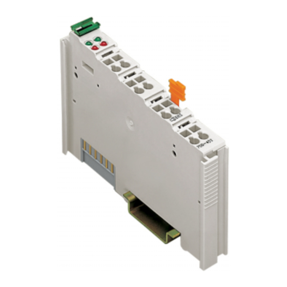
750-454 [2 AI 4-20 mA, Differential Inputs] • 7 View 2 I/O Modules 2.1 Digital Output Modules 2.1.1 750-454 [2 AI 4-20 mA, Differential Inputs] 2-Channel Analog Input Module (4-20mA, differential inputs) 2.1.1.1 View 13 14 Function AI 1 Function AI 2... -
Page 8: Description
This module has no power contacts. For field supply to downstream I/O modules, a supply module will be needed. The analog input module 750-454 and its variations can be used with all couplers/controllers of the WAGO-I/O-SYSTEM 750 (except for the economy types 750-320, -323, -324 and -327). -
Page 9: Display Elements
750-454 [2 AI 4-20 mA, Differential Inputs] • 9 Display Elements 2.1.1.4 Display Elements Channel Meaning State Function No operational readiness or the internal data bus communication is interrupted Function green AI 1 Operational readiness and trouble- free internal data bus... -
Page 10: Technical Data
10 • 750-454 [2 AI 4-20 mA, Differential Inputs] Technical Data 2.1.1.6 Technical Data Module Specific Data Number of inputs Voltage supply via system voltage DC /DC Current consumption (internal) 70 mA typ. Common mode voltage 35 V max. Signal current 4 mA... -
Page 11: Process Image
II 3 G EEx nA II T4 Conformity Marking More Information Detailed references to the approvals are listed in the document "Overview Approvals WAGO-I/O-SYSTEM 750", which you can find on the CD ROM ELECTRONICC Tools and Docs (Item-No.: 0888-0412) or in the internet under: www.wago.com... -
Page 12: Standard Data Format
Some fieldbus systems can process input channel status information by means of a status byte. This status byte can be displayed via the starting tool WAGO-I/O-CHECK 2. However, processing via the coupler / controller is optional, which means that accessing or parsing the status information depends on the fieldbus system. -
Page 13: Special Data Format
• 13 Process Image 2.1.1.7.2 Special Data Format To digitalize the measurement value, the variation 750-454/000-002 uses another resolution as the standard module. For this variation, the input current ranging from 4 mA to 20 mA is scaled on the numerical values ranging from 0x0000 to 0x0F99. - Page 14 14 • 750-454 [2 AI 4-20 mA, Differential Inputs] Process Image WAGO-I/O-SYSTEM 750 I/O Modules...
- Page 15 • 15 Process Image To digitalize the measurement value, the variation 750-454/000-200 uses a format adapted for the S5 control systems using FB 250. For this variation, the input current ranging from 4 to 20 mA is scaled on the numerical values ranging from 0x1000 to 0x5001.
- Page 16 WAGO Kontakttechnik GmbH & Co. KG Postfach 2880 • D-32385 Minden Hansastraße 27 • D-32423 Minden Phone: 05 71/8 87 – 0 Fax: 05 71/8 87 – 1 69 E-Mail: info@wago.com Internet: http://www.wago.com...
Need help?
Do you have a question about the 750-454 and is the answer not in the manual?
Questions and answers