Table of Contents
Advertisement
Quick Links
Advertisement
Chapters
Table of Contents

Related Manuals for WAGO 750 Series


Summary of Contents for WAGO 750 Series
- Page 1 Manual WAGO-I/O-SYSTEM 750 753-646 KNX/EIB/TP1 Module Router Mode Version 1.1.0...
- Page 2 We wish to point out that the software and hardware terms as well as the trademarks of companies used and/or mentioned in the present manual are generally protected by trademark or patent. WAGO is a registered trademark of WAGO Verwaltungsgesellschaft mbH. Manual Version 1.1.0...
-
Page 3: Table Of Contents
Legal Bases .................... 9 2.1.1 Subject to Changes ................9 2.1.2 Personnel Qualifications ..............9 2.1.3 Use of the WAGO-I/O-SYSTEM 750 in Compliance with Underlying Provisions ..................9 2.1.4 Technical Condition of Specified Devices......... 10 2.1.4.1 Disposal ..................10 Safety Advice (Precautions) ..............11 Device Description .................. - Page 4 Table of Contents 753-646 KNX/EIB/TP1 Module I/O Modules with Pluggable Wiring Level (Series 753) ......38 6.3.1 Coding ..................... 39 6.3.2 Plug Removal .................. 41 List of Figures ....................42 List of Tables ....................43 Manual Version 1.1.0...
-
Page 5: Notes About This Documentation
Manual by third parties that violate pertinent copyright provisions is prohibited. Reproduction, translation, electronic and phototechnical filing/archiving (e.g., photocopying) as well as any amendments require the written consent of WAGO Kontakttechnik GmbH & Co. KG, Minden, Germany. Non-observance will involve the right to assert damage claims. Manual... -
Page 6: Symbols
Notes about this Documentation 753-646 KNX/EIB/TP1 Module Symbols Personal Injury! Indicates a high-risk, imminently hazardous situation which, if not avoided, will result in death or serious injury. Personal Injury Caused by Electric Current! Indicates a high-risk, imminently hazardous situation which, if not avoided, will result in death or serious injury. - Page 7 Notes about this Documentation 753-646 KNX/EIB/TP1 Module Additional Information: Refers to additional information which is not an integral part of this documentation (e.g., the Internet). Manual Version 1.1.0...
-
Page 8: Number Notation
Font Conventions Table 2: Font Conventions Font Type Indicates italic Names of paths and data files are marked in italic-type. e.g.: C:\Program Files\WAGO Software Menu Menu items are marked in bold letters. e.g.: Save > A greater-than sign between two names means the selection of a menu item from a menu. -
Page 9: Important Notes
2.1.1 Subject to Changes WAGO Kontakttechnik GmbH & Co. KG reserves the right to provide for any alterations or modifications. WAGO Kontakttechnik GmbH & Co. KG owns all rights arising from the granting of patents or from the legal protection of utility patents. -
Page 10: Technical Condition Of Specified Devices
These modules contain no parts that can be serviced or repaired by the user. The following actions will result in the exclusion of liability on the part of WAGO Kontakttechnik GmbH & Co. KG: •... -
Page 11: Safety Advice (Precautions)
Install the device only in appropriate housings, cabinets or in electrical operation rooms! The WAGO-I/O-SYSTEM 750 and its components are an open system. As such, install the system and its components exclusively in appropriate housings, cabinets or in electrical operation rooms. Allow access to such equipment and fixtures to authorized, qualified staff only by means of specific keys or tools. - Page 12 Important Notes 753-646 KNX/EIB/TP1 Module Clean only with permitted materials! Clean housing and soiled contacts with propanol. Do not use any contact spray! Do not use any contact spray. The spray may impair contact area functionality in connection with contamination. Do not reverse the polarity of connection lines! Avoid reverse polarity of data and power supply lines, as this may damage the devices involved.
-
Page 13: Device Description
KNX IP Controller 750-889, the first module will always be in router mode, along with all other KNX modules. If using a different WAGO controller, the KNX module will operate in device mode only. The KNX module may not be used at couplers. - Page 14 (see Chapter “Display Elements”). Additional Information Detailed information about the KNX IP controller and programming is available at http://www.wago.com. The KNX module may also be operated in the Device mode. For more about this go to the manual at http://www.wago.com. Manual...
-
Page 15: View
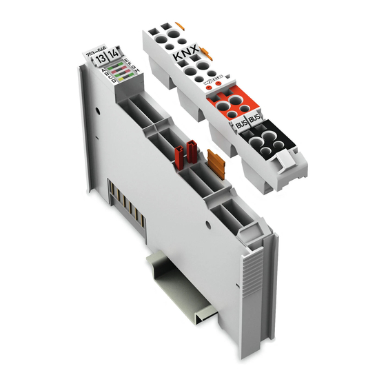
Device Description 753-646 KNX/EIB/TP1 Module View Figure 1: View Table 3: Legend for Figure “View” Pos. Description Details See Section Marking possibility with Mini- Status-LEDs “Device Description” > “Display Elements” Data contacts “Device Description” > “Connectors” Release tab “Mounting” > “Inserting and Removing Devices”... -
Page 16: Connectors
Device Description 753-646 KNX/EIB/TP1 Module Connectors 3.2.1 Data Contacts/Local Bus Communication between the fieldbus coupler/controller and the I/O modules as well as the system supply of the I/O modules is carried out via the local bus. It is comprised of 6 data contacts, which are available as self-cleaning gold spring contacts. -
Page 17: Cage Clamp
Device Description 753-646 KNX/EIB/TP1 Module ® 3.2.2 CAGE CLAMP Connectors ® Figure 3: CAGE CLAMP Connectors ® Table 4: Legend for Figure “CAGE CLAMP Connectors” Channel Connector Function Not connected Programming button + KNX bus - KNX bus Not connected Programming button + KNX bus - KNX bus... -
Page 18: Display Elements
Device Description 753-646 KNX/EIB/TP1 Module Display Elements Figure 4: Display Elements Table 5: Legend for Figure “Display Elements” LED Designation State Function Operating mode Router not active Router mode Operating mode Router active Flashing Synchronization KNX programming mode not active KNX programming mode KNX programming mode active Flashing... -
Page 19: Operating Elements
Device Description 753-646 KNX/EIB/TP1 Module Operating Elements The I/O module has two programming button connections (see figure below) for parameterization of the KNX module in the device mode. Figure 5: Programming Button Actuation of the buttons is requested by the engineering tool software (ETS) during startup of the module. -
Page 20: Schematic Diagram
Device Description 753-646 KNX/EIB/TP1 Module Schematic Diagram Figure 6: Schematic Diagram Manual Version 1.1.0... -
Page 21: Technical Data
Device Description 753-646 KNX/EIB/TP1 Module Technical Data 3.6.1 Device Data Table 6: Technical Data – Device Width 12 mm Weight Approx. 55 g (incl. plug) 3.6.2 Supply Table 7: Technical Data – Supply Voltage supply (KNX) Via KNX power supply unit Current consumption (KNX) 5 mA Voltage supply (internal) -
Page 22: Climatic Environmental Conditions
Device Description 753-646 KNX/EIB/TP1 Module 3.6.5 Climatic Environmental Conditions Table 11: Technical Data – Climatic Environmental Conditions Surrounding air temperature 0 °C … 55 °C (operation) −20 °C … +60 °C Surrounding air temperature (operation) for components with extended temperature range (750- xxx/025-xxx) Surrounding air temperature (storage) −25 °C …... -
Page 23: Approvals
Device Description 753-646 KNX/EIB/TP1 Module Approvals The following approvals have been granted to 753-646 I/O modules: Conformity Marking UL508 KNX certified The following ship approvals have been granted to 753-646 I/O modules: ABS (American Bureau of Shipping) BV (Bureau Veritas) DNV (Det Norske Veritas) Class B GL (Germanischer Lloyd) -
Page 24: Standards And Guidelines
753-646 KNX/EIB/TP1 Module More information about approvals. Detailed references to the approvals are listed in the document “Overview Approvals WAGO-I/O-SYSTEM 750”, which you can find via the internet under: www.wago.com > SERVICES > DOWNLOADS > Additional documentation and information on automation products > WAGO-I/O-SYSTEM 750 > System Description. -
Page 25: Function Description
Only in a later step must the IEC application be programmed for communication with any subsequently plugged modules. If the KNX module is used with a different WAGO controller, gateway functions can also be implemented to other fieldbus systems, such as LON, PROFIBUS, etc. -
Page 26: Startup Behavior Of The Knx/Eib/Tp1 Module In The Router Mode
Startup Behavior of the KNX/EIB/TP1 Module in the Router Mode A node consisting of a WAGO KNX IP controller 750-889 and at least one KNX module is set up and power supplied to operate the KNX module in the Router mode. -
Page 27: Figure 7: Startup Behavior Of The Knx/Eib/Tp1 Module 753-646 In The Router Mode
Function Description 753-646 KNX/EIB/TP1 Module Figure 7: Startup Behavior of the KNX/EIB/TP1 Module 753-646 in the Router Mode Manual Version 1.1.0... -
Page 28: Network Structure
Function Description 753-646 KNX/EIB/TP1 Module Network Structure In a conventional two-wire TP1 network (see Figure below) a distinction is made between backbone, ranges and lines. Up to 15 ranges can be coupled at a KNX backbone using range couplers. Each of these ranges, in turn, is broken down into a maximum of 15 lines that are connected to the range line via line couplers. -
Page 29: Knxnet/Ip Routers As Range Couplers
Function Description 753-646 KNX/EIB/TP1 Module 4.2.1 KNXnet/IP Routers as Range Couplers Line and main lines can be established in the normal manner when the KNXnet/IP router is used as a range coupler. Instead of a range coupler being used, the KNXnet/IP router is now employed which uses the IP network as a range line (see Figure below). -
Page 30: Knxnet/Ip Routers As Line Couplers
Function Description 753-646 KNX/EIB/TP1 Module 4.2.2 KNXnet/IP Routers as Line Couplers The KNXnet/IP router acts as a link between the IP backbone and the lines when it is used as a line coupler. Range couplers cannot be used in this topology. They are no longer required here anyway (see Figure below). -
Page 31: Knxnet/Ip Routers In A Mixed Topology
Function Description 753-646 KNX/EIB/TP1 Module 4.2.3 KNXnet/IP Routers in a Mixed Topology If required, routers can also be used as range and line couplers together in a network. In this example (see Figure below) the KNXnet/IP router with the physical address 1.1.0 functions as a line coupler, whereas the KNXnet/IP router with the physical address 2.0.0 acts as a range coupler. -
Page 32: Installation Instructions
Function Description 753-646 KNX/EIB/TP1 Module Installation Instructions KNX plug only for use with KNX/EIB/TP1 module 753-646! The KNX plug is intended exclusively for the KNX/EIB/TP1 module 753-646, because the plug is bridged between the two KNX bus conductors “+” and the two KNX conductors “-”. - Page 33 Commissioning and configuration of the KNX/EIB/TP1 module 753-646 in the Router mode are performed via the KNX IP controller 750-889. Loss of telegrams possible when performing configuration during ongoing operation! Configuration performed with WAGO-I/O-CHECK in operating mode can lead to the loss of telegrams. Manual Version 1.1.0...
-
Page 34: Process Image
Process Image 753-646 KNX/EIB/TP1 Module Process Image The KNX module provides the controller with a 24 byte input and output process image via a logical channel. Two status bytes and two control bytes provide the control of the data flow. The byte length of purely KNX telegrams can vary between a minimum of 7 bytes and a maximum of 64 bytes. -
Page 35: Mounting
Don't forget the bus end module! Always plug a bus end module (750-600) onto the end of the fieldbus node! You must always use a bus end module at all fieldbus nodes with WAGO-I/O- SYSTEM 750 fieldbus couplers/controllers to guarantee proper data transfer. -
Page 36: Inserting And Removing Devices
Mounting 753-646 KNX/EIB/TP1 Module Inserting and Removing Devices Perform work on devices only if they are de-energized! Working on energized devices can damage them. Therefore, turn off the power supply before working on the devices. 6.2.1 Inserting the I/O Module Position the I/O module so that the tongue and groove joints to the fieldbus coupler/controller or to the previous or possibly subsequent I/O module are engaged. -
Page 37: Removing The I/O Module
Mounting 753-646 KNX/EIB/TP1 Module 6.2.2 Removing the I/O Module Note Remove pluggable wiring! Before removing a 753 Series I/O Module from the node, you must first remove the plug (pluggable wiring) from the I/O module (see section “Plug Removal”)! Remove the I/O module from the node by pulling the tab. Figure 14: Removing the I/O Module (Example) Electrical connections for data or power jumper contacts are disconnected when removing the I/O module. -
Page 38: I/O Modules With Pluggable Wiring Level (Series 753)
Mounting 753-646 KNX/EIB/TP1 Module I/O Modules with Pluggable Wiring Level (Series 753) For wiring, a plug is plugged into the bottom of the module of all 753 Series I/O modules. The plug can be completely removed together with the wiring, simplifying replacement of defective modules from the assembly. -
Page 39: Coding
Mounting 753-646 KNX/EIB/TP1 Module Figure 17: Attachment of Cable Binders 6.3.1 Coding Coding using small plastic pins and sockets facilitates mating of the I/O module with the appropriate plug. Insert the pin into the socket. Figure 18: Assembling the Coding Fingers Position the assembled coding fingers in the I/O module. -
Page 40: Figure 20: Plugging The Plug Into Place
Mounting 753-646 KNX/EIB/TP1 Module Figure 20: Plugging the Plug into Place When the plug is removed the sockets remain in the I/O module. The coded plug can only fit in the corresponding coded I/O module (see figures below). Figure 21: “Sure Match” Coding Fingers Manual Version 1.1.0... -
Page 41: Plug Removal
Mounting 753-646 KNX/EIB/TP1 Module 6.3.2 Plug Removal Remove the plug from the I/O module by pulling the orange pull tab on the plug toward the top of the I/O module. Figure 22: Pulling the Pull Tab The plug detaches from the I/O module. Figure 23: Removing the Plug Without Tools Alternatively, you can also use a standard screwdriver at the position shown (in the figure below) to remove the plug. -
Page 42: List Of Figures
List of Figures 753-646 KNX/EIB/TP1 Module List of Figures Figure 1: View ....................15 Figure 2: Data Contacts ..................16 ® Figure 3: CAGE CLAMP Connectors ..............17 Figure 4: Display Elements.................18 Figure 5: Programming Button ................19 Figure 6: Schematic Diagram ................20 Figure 7: Startup Behavior of the KNX/EIB/TP1 Module 753-646 in the Router Mode ......................27 Figure 8: Traditional TP1 Network ..............28 Figure 9: KNXnet/IP Router as Range Coupler ..........29... -
Page 43: List Of Tables
List of Tables 753-646 KNX/EIB/TP1 Module List of Tables Table 1: Number Notation ................... 8 Table 2: Font Conventions .................. 8 Table 3: Legend for Figure “View” ..............15 ® Table 4: Legend for Figure “CAGE CLAMP Connectors” ........17 Table 5: Legend for Figure “Display Elements”...........18 Table 6: Technical Data –... - Page 44 WAGO Kontakttechnik GmbH & Co. KG Postfach 2880 • 32385 Minden Hansastraße 27 • 32423 Minden Phone: 0571/887 – 0 Fax: 0571/887 – 169 E-Mail: info@wago.com Internet: http://www.wago.com...
Need help?
Do you have a question about the 750 Series and is the answer not in the manual?
Questions and answers