
Related Manuals for Waters Vion IMS QTof


Summary of Contents for Waters Vion IMS QTof
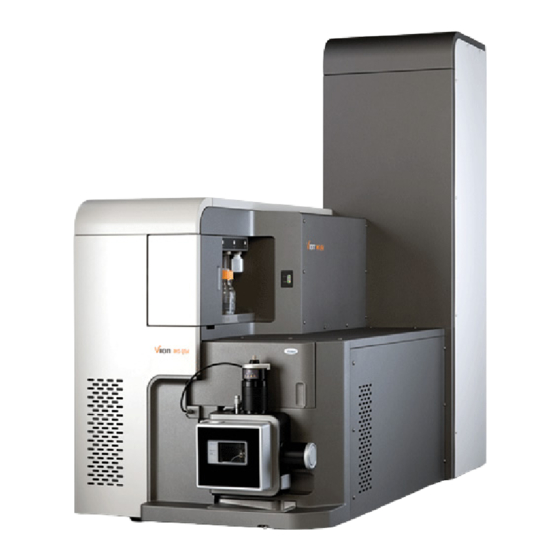
- Page 1 Waters Vion IMS QTof Overview and Maintenance Guide 715005046 Copyright © Waters Corporation 2021 Version 03 All rights reserved...
-
Page 2: General Information
This document is believed to be complete and accurate at the time of publication. In no event shall Waters Corporation be liable for incidental or consequential damages in connection with, or arising from, its use. For the most recent revision of this document, consult the Waters website (www.waters.com). -
Page 3: Customer Comments
We seriously consider every customer comment we receive. You can reach us at tech_comm@waters.com. Contacting Waters Contact Waters with enhancement requests or technical questions regarding the use, transportation, removal, or disposal of any Waters product. You can reach us via the Internet, telephone, fax, or conventional mail. Waters contact information Contacting medium... -
Page 4: Safety Considerations
Milford, MA 01757 Safety considerations Some reagents and samples used with Waters instruments and devices can pose chemical, biological, or radiological hazards (or any combination thereof). You must know the potentially hazardous effects of all substances you work with. Always follow Good Laboratory Practice (GLP), and consult your organization’s standard operating procedures as well as your local... - Page 5 Solvent leakage hazard The source exhaust system is designed to be robust and leak-tight. Waters recommends that you perform a hazard analysis, assuming a maximum leak into the laboratory atmosphere of 10% LC eluate. Warning: To avoid exposure to toxic substances and biohazards from O-ring leaks in the source exhaust system, observe these precautions: •...
- Page 6 Glass breakage hazard Warning: To avoid injuries from broken glass, falling objects, or exposure to biologically hazardous, toxic, or corrosive substances, never place containers on top of the instrument or on its front covers. High temperature hazard Warning: To avoid burn injuries, before performing maintenance operations that involve handling components inside the mass spectrometer's ion source, allow the source interior to cool.
-
Page 7: Electrical Power Safety Notice
Do not dispose of the instrument or return it to Waters for repair until the authority responsible for approving its removal from the premises specifies the extent of decontamination required and the level of residual contamination permissible. -
Page 8: Safety Advisories
Safety advisories Consult the "Safety advisories" appendix in this publication for a comprehensive list of warning advisories and notices. Operating the device When operating the device, follow standard quality-control (QC) procedures and the guidelines presented in this section. Applicable symbols The following symbols can be present on the device, system, or packaging. -
Page 9: Intended Use Of The Vion Ims Qtof
Intended use of the Vion IMS QTof Waters designed the Vion IMS QTof for use as a routine analytical tool to deliver authenticated mass measurement. The Vion IMS QTof is for research and routine analysis only and is not for use in diagnostic applications. -
Page 10: Quality Control
Quality control Routinely run three QC samples that represent subnormal, normal, and above-normal levels of a compound. If sample trays are the same or very similar, vary the location of the QC samples in the trays. Ensure that QC sample results fall within an acceptable range, and evaluate precision from day to day and run to run. -
Page 11: Table Of Contents
Equipment misuse notice....................... vii Safety advisories........................... viii Operating the device..........................viii Applicable symbols........................viii Audience and purpose........................ix Intended use of the Vion IMS QTof....................ix Calibrating............................ix Quality control..........................x EMC considerations..........................x FCC radiation emissions notice....................... x Canada spectrum management emissions notice................x ISM classification: ISM group 1 class A................... - Page 12 2.1 Starting the mass spectrometer..................... 29 2.1.1 Verifying the instrument’s state of readiness................ 30 2.1.2 Automated setup........................31 2.1.3 Flow rates for the Vion IMS QTof system................31 2.2 Preparing the Fluidics system......................31 2.2.1 Installing the reservoir bottles....................32 2.2.2 Installing the low-volume vials....................33 2.2.3 Purging the fluidics........................33...
- Page 13 4.1.3 NanoFlow gas supply......................46 4.1.4 Purge gas..........................46 4.1.5 Sprayer platform adjuster assembly..................46 4.2 Selecting and configuring the NanoLockSpray source..............47 4.3 Deploying the sprayer platform adjuster assembly................ 47 4.3.1 Moving the sprayer platform out of the source..............47 4.3.2 Moving the sprayer platform into the source.................48 4.4 Setting up the camera........................
- Page 14 5.13 Cleaning the sampling cone assembly..................66 5.13.1 Removing the sampling cone assembly from the source........... 66 5.13.2 Disassembling the sampling cone assembly..............67 5.13.3 Cleaning the sample cone and cone gas nozzle..............69 5.13.4 Assembling the sampling cone assembly................71 5.13.5 Fitting the sampling cone assembly to the source..............
- Page 15 A.1 Warning symbols..........................169 A.2 Notices............................170 A.3 Bottles Prohibited symbol......................170 A.4 Required protection........................171 A.5 Warnings that apply to all Waters instruments and devices............171 A.6 Warnings that address the replacement of fuses.................175 A.7 Electrical symbols........................176 A.8 Handling symbols.........................177 B External Connections..................... 179 B.1 Mass spectrometer: External wiring and vacuum connections............
- Page 16 B.7 Connecting the workstation (systems with no ACQUITY LC)............190 B.7.1 Connecting to the workstation.................... 190 B.7.2 Connecting the workstation to the power source..............191 B.8 Connecting Ethernet cables (systems with ACQUITY LC)............191 B.9 Input/output signal connectors..................... 192 B.9.1 Signal connections......................194 B.10 Connecting the contact-closure cable to an ACQUITY LC............
-
Page 17: Waters Vion Ims Qtof Overview
The automated setup feature is not available for the optional APGC source. In Waters documents, the term “fluidics” refers to the instrument’s onboard system that delivers sample and solvent to the probe of the mass spectrometer. It can also denote plumbing components and fluid pathways within and between system modules. -
Page 18: Acquity Vion Ims Qtof Uplc/Ms Systems
• ACQUITY UPLC I-Class • ACQUITY PREMIER The ACQUITY Vion IMS QTof UPLC/MS system includes an ACQUITY UPLC system. The Waters Vion IMS QTof is fitted with either the LockSpray ESI/APCI source or the NanoLockSpray source (with ACQUITY UPLC M-Class only). Notes: •... -
Page 19: Software And Data System
An ACQUITY UPLC I-Class system is illustrated. 1.1.2.1.1 ACQUITY UPLC/MS Vion IMS QTof systems The Waters Vion IMS QTof is compatible with the ACQUITY UPLC systems. If you are not using an ACQUITY UPLC system, refer to the documentation relevant to your LC system. -
Page 20: Lockspray Source And Ionization Modes
• Configuring the system • Creating these method types, which define operating parameters for a run: • MS • HDMS • MS/MS • MRM • MS • HDMS • DDA • HSMSMS • HSMRM • HD-DDA • Using the automated setup feature to automatically tune and mass calibrate the mass spectrometer •... -
Page 21: Electrospray Ionization (Esi)
You can use the LockSpray source with the ESI and APCI ionization modes (see Configuring the LockSpray Source (Page 36)). Figure 1–2: Vion IMS QTof fitted with LockSpray source LockSpray source Fluidics access door Bottle tray 1.2.1 Electrospray ionization (ESI) In ESI, a strong electrical charge is applied to the eluent as it emerges from a nebulizer. -
Page 22: Nanolockspray Source And Ionization Modes
The APCI interface consists of the ESI/APCI enclosure fitted with a corona pin and an IonSABRE II probe. Mobile phase from the LC column enters the probe, where it is pneumatically converted to an aerosol, rapidly heated, and vaporized or gasified at the probe tip. Figure 1–3: APCI mode Corona pin Sample cone... -
Page 23: Apgc
1.2.4 APGC The Waters APGC couples an Agilent GC with the Vion IMS QTof. Doing so enables you to perform LC and GC analyses in the same system, without compromising performance. The APGC provides complementary information to the LC/MS instrument, enabling analysis of compounds of low molecular weight and low-to-intermediate polarity. -
Page 24: Physical Layout Of The Fluidics System
For reference flows for the LockSpray source or NanoLockSpray source, the Fluidics system delivers lock mass solution from reservoir bottle B, or for extended operating hours, from a separate, external bottle of lock mass solution. Tip: You can fit a 250-mL lock mass solution bottle to port B of the Fluidics system, to accommodate longer operating hours without the need for external bottles. -
Page 25: System Operation
Reservoir bottle B (LockSpray) Note: The Fluidics pump access panel is removed in the figure. The Fluidics system consists of these components: • A sample delivery system composed of a pump, sample selector valve, and a divert valve used for LC and probe connections. •... - Page 26 5. The ion beam is focused in an ion guide before it enters the quadrupole, where the ions are filtered according to their mass-to-charge ratio. 6. The mass-separated ions pass through a collision cell where they can undergo collision- induced dissociation (CID). 7.
-
Page 27: Leak Sensors
1.5 mL of accumulated leaked liquid in its surrounding reservoir. At the same time, the software displays an error message alerting you that a leak has developed. Consult the Waters ACQUITY UPLC Leak Sensor Maintenance Instructions (71500082506) for complete details. - Page 28 A vacuum isolation valve isolates the source from the mass analyzer, allowing cleaning of the sample cone without the need to vent the instrument to atmospheric pressure. March 17, 2021, 715005046 Ver. 03 Page 28...
-
Page 29: Preparing The Mass Spectrometer For Operation
1. Ensure that all external connections to the mass spectrometer are made, as detailed in External Connections (Page 179). 2. Turn on the instrument server or workstation PC. 3. Power-on the Vion IMS QTof at the power outlet. 4. Power-on the ACQUITY instruments. Result: Each system component runs a series of startup tests. -
Page 30: Verifying The Instrument's State Of Readiness
• During initialization, the binary solvent manager’s and sample manager’s status LED flashes green. • After the instruments successfully power-on, all power LEDs show steady green. The binary solvent manager’s flow LED, the sample manager’s run LED, and the mass spectrometer’s status LED remain unlit. -
Page 31: Automated Setup
• Calibrates the IMS system to allow direct measurement of collision cross section values. 2.1.3 Flow rates for the Vion IMS QTof system The Vion IMS QTof system can run at high flow rates. To optimize desolvation, and thus sensitivity, run the system at appropriate gas flows and desolvation temperatures. -
Page 32: Installing The Reservoir Bottles
2.2.1 Installing the reservoir bottles Use standard reservoir bottles (30 mL) for instrument setup and calibration. Use the Low-volume Adaptor Kit (included) to infuse smaller volumes. The low-volume vials have a volume of 1.5 mL. Optionally, you can use a 250-mL bottle in Fluidics port B, to infuse larger volumes of LockSpray solution. -
Page 33: Installing The Low-Volume Vials
2.2.2 Installing the low-volume vials To install the low-volume vials: 1. If a standard reservoir bottle is fitted, remove it. 2. Screw each low-volume adaptor into the manifold, and finger-tighten it. Warning: To avoid laceration injuries caused by the shattering of fragile, low- volume, glass vials, take care when installing them and never use force. -
Page 34: Leaving The Mass Spectrometer In Standby Mode
Figure 2–2: Electronics override and power switch location Electronics switches Vion IMS QTof Figure 2–3: Electronics switches Override switch Electronics switch 2. Move the electronics switch into the downward position. 3. Wait between 5 and 10 seconds, and then return the electronics switch to the upward position. -
Page 35: Emergency Shutdown
Tip: After you return the instrument to Operate mode, the LockSpray source’s temperature requires up to 30 minutes to stabilize at the relatively high temperatures needed for UPLC operation. 2.5 Emergency shutdown To shut down the mass spectrometer in an emergency: Warning: To avoid electric shock, observe the following procedure to isolate the instrument from the main power supply. -
Page 36: Configuring The Lockspray Source
For more information about using ESI mode, see the Vion IMS QTof system online Help. Note: If you are using a tool-free ESI probe, to install or remove the probe, see the Waters Tool- Free Probe Maintenance Guide Supplement (715005492). - Page 37 To install the ESI probe: Warning: To avoid harmless, static-like electric shock, before you touch any external surfaces marked with the high-voltage warning symbol, ensure that the mass spectrometer is in Standby mode. 1. Prepare the instrument so that you can work safely on the source (see Preparing the instrument for working on the source (Page 53)).
- Page 38 Figure 3–2: ESI probe mounted on the LockSpray source enclosure Probe locking ring Source enclosure release ESI high-voltage cable Vernier probe adjuster ESI probe 4. Tighten the probe locking ring to secure the probe in place. Tip: An automatic pressure test is performed when the probe is correctly seated in position.
- Page 39 Figure 3–3: Securing the union Tubing connection ESI probe Divert valve (port 2) Note: • To allow the fluidics access door to close, feed the PEEK tubing from the ESI probe through the channel underneath the access door, as shown. •...
-
Page 40: Removing The Esi Probe
For more information about using APCI mode, see the Vion IMS QTof system online Help. Note: If you are using a tool-free APCI probe, to install or remove the probe, see the Waters Tool-Free Probe Maintenance Guide Supplement (715005492). March 17, 2021, 715005046 Ver. 03... -
Page 41: Installing The Ionsabre Ii Probe
3.3.1 Installing the IonSABRE II probe Required materials • Chemical-resistant, powder-free gloves • Utility knife or PEEK tubing cutter To install the IonSABRE II probe: Warning: To avoid harmless, static-like electric shock, before you touch any external surfaces marked with the high-voltage warning symbol, ensure that the mass spectrometer is in Standby mode. - Page 42 Tip: An automatic pressure test is performed when the probe is correctly seated in position. Figure 3–7: IonSABRE II probe mounted on the source enclosure Probe locking ring Source enclosure release APCI high-voltage cable Vernier probe adjuster APCI probe 4. Open the access door to the fluidics valves (see the figure in Physical layout of the Fluidics system (Page 24)).
-
Page 43: Removing The Ionsabre Ii Probe
• If you are replacing the tubing supplied with the instrument, you must minimize the length of the tube connecting the divert valve to the IonSABRE II probe. Doing so minimizes delays and dispersion. • When cutting the tubing to length, cut it squarely. 6. -
Page 44: Configuring The Nanolockspray Source
4 Configuring the NanoLockSpray Source The Waters NanoLockSpray ion source enables the optimized co-introduction of sample and lock mass compound directly into the ion source. This feature provides authenticated, exact-mass measurement in MS mode at low flow rates. 4.1 Overview of the NanoLockSpray source Figure 4–1: NanoLockSpray source... - Page 45 Y-position adjuster Thumbscrew Sprayer-platform adjuster assembly Thumbscrew (on left-hand side of sprayer platform) X-position adjuster Sprayer safety cover Clear sprayer shield (fitted) Z-position adjuster LockSpray sprayer inlet The NanoLockSpray source enclosure holds two NanoFlow sprayers positioned orthogonally with respect to one another. The sample flows through one sprayer and the lock mass reference solution through the other.
-
Page 46: Sample Sprayer
LockSpray inlet Spray indexing permits acquisition of sample and LockSpray data in separate data channels, and the baffle design ensures negligible cross-talk between the two sprays. The LockSpray data are used to calculate a correction factor for the mass scale calibration, which is then applied to the sample data, providing exact mass information. -
Page 47: Selecting And Configuring The Nanolockspray Source
4.2 Selecting and configuring the NanoLockSpray source The Universal NanoFlow sprayer is installed as standard equipment on the NanoLockSpray source. For installation and maintenance details, see the Universal NanoFlow Sprayer Installation and Maintenance Guide (71500110107). When fitted, the NanoLockSpray source is automatically recognized by the software. Requirement: The sprayer platform must be inserted in the source enclosure for correct identification of the source. -
Page 48: Moving The Sprayer Platform Into The Source
4.3.2 Moving the sprayer platform into the source To move the sprayer platform into the source: Warning: To avoid harmless, static-like electrical shock, ensure that the safety cover is in place over the sprayer. 1. Confirm that the clear sprayer shield is in place and secured (see Overview of the NanoLockSpray source (Page 44)). -
Page 49: Adjusting The Sprayer Tip Position
Figure 4–3: Camera Control view of sprayers and sample cone: Sample cone Baffle Sprayer tip Sample sprayer 4.5 Adjusting the sprayer tip position To adjust the tip position: 1. Using the X-, Y-, and Z-position adjuster controls on the adjuster assembly, move the sample-sprayer tip close to the sampling cone and baffle (see Setting up the camera (Page 48)). -
Page 50: Optional Glass Capillary Sprayer
2. Fine-tune the position of the sprayer while acquiring a spectrum of a standard compound. For information about optimizing the nanoLockSpray source, see the instrument's online Help file. Tips: • If you observe an electrical discharge between the sprayer tip and baffle, move the tip farther from the baffle, or reduce the capillary voltage. -
Page 51: Maintenance Procedures
5 Maintenance procedures This section provides the maintenance guidelines and procedures necessary to maintain the mass spectrometer's performance. Keep to a maintenance schedule, and perform maintenance as required and described in this section. 5.1 Maintenance schedule The following table lists periodic maintenance schedules that ensure optimum instrument performance. -
Page 52: Spare Parts
5.2 Spare parts Waters recommends that you replace only the parts mentioned in this document. For spare parts details, see the Waters Quality Parts Locator on the Waters Web site’s Services & Support page (http://www.waters.com/waters/en_US/Spare-Parts/nav.htm?cid=511444). 5.3 Safety and handling... -
Page 53: Preparing The Instrument For Working On The Source
Warning: Observe Good Laboratory Practice (GLP) at all times, particularly when working with hazardous materials. Consult the Safety Data Sheets regarding the solvents you use. Additionally, consult the safety representative for your organization regarding its protocols for handling such materials. Warning: To avoid electric shock, do not remove protective panels from the device. -
Page 54: Using Unifi Software To Prepare The Instrument For Working On The Source
• If you are removing an IonSABRE II probe, see Removing the IonSABRE II probe (Page 43). • If you are removing a tool-free ESI or APCI probe, see the Waters Tool-Free Probe Maintenance Guide Supplement (715005492). March 17, 2021, 715005046 Ver. 03 Page 54... - Page 55 3. Slide open the instrument’s source interface door. Figure 5–1: Waters ACQUITY Vion IMS QTof UPLC/MS system Fluidics system Vion IMS QTof Binary solvent manager Sample Manager Column heater Sample organizer (optional) Solvent tray LockSpray source enclosure Bottle tray Note: An ACQUITY UPLC I-Class system is illustrated.
-
Page 56: Fitting The Source Enclosure To The Instrument
Notice: To avoid damaging the sample inlet, when removing a NanoLockSpray source enclosure, you must slide the sprayer platform out of the source enclosure before you open the enclosure. 5. Pull the source enclosure release (located at the bottom, right-hand side) outward and swing open the enclosure. -
Page 57: Installing And Removing The Corona Pin
To fit the source enclosure to the instrument: Warning: To avoid puncture wounds, take great care while working with the source enclosure open if one or both of these conditions apply: • An ESI probe is fitted (the probe’s tip is sharp). •... - Page 58 Warning: To avoid burn injuries, take great care while working with the source enclosure open. 2. Pull the source enclosure release (located at the bottom, right-hand side) outward, and swing open the enclosure. 3. Remove the blanking plug from the corona pin mounting contact. Tip: Store the blanking plug in a safe location.
-
Page 59: Removing The Corona Pin From The Source
6. Look through the source window, and use the vernier probe adjuster (see the figure in probe, mounted on the LockSpray source enclosure (Page 36)) to position the ESI probe tip so that it is pointing approximately midway between the tips of the sample cone and the corona pin. -
Page 60: Operating The Source Isolation Valve
Figure 5–5: Corona pin Corona pin 4. Fit the blanking plug to the corona pin mounting contact. Figure 5–6: Blanking plug fitted to the corona pin mounting contact Corona pin mounting contact blanking plug 5. Close the source enclosure. 5.7 Operating the source isolation valve You must close the source isolation valve to isolate the source from the instrument vacuum system for certain maintenance procedures. -
Page 61: Closing The Source Isolation Valve
5.7.1 Closing the source isolation valve To close the source isolation valve before starting a maintenance procedure: 1. Prepare the instrument for working on the source (see Preparing the instrument for working on the source (Page 53)). Warning: To avoid burn injuries, take great care while working with the source enclosure open. -
Page 62: Opening The Source Isolation Valve
5.7.2 Opening the source isolation valve To open the source isolation valve after completing a maintenance procedure: Warning: To avoid puncture wounds, take great care while working with the source enclosure open if one or both of these conditions apply: •... -
Page 63: Cleaning The Instrument Case
Figure 5–9: O-ring removal kit Tool 1 Tool 2 To remove an O-ring: Notice: To avoid damaging the component when removing an O-ring or seal from it, ensure that you do not scratch the component with the removal tool. Use the tools as aids to pull the O-ring or seal from its groove. Tip: If you do not plan to reuse the O-ring or seal, you can use the forked end of tool 1 to impale the O-ring or seal to remove it. - Page 64 Figure 5–10: Nitrogen exhaust trap bottle To laboratory exhaust port From instrument pilot valve port Bottle support Nitrogen exhaust trap bottle From instrument exhaust connection One-way valve Required materials Chemical-resistant, powder-free gloves March 17, 2021, 715005046 Ver. 03 Page 64...
-
Page 65: Maintaining The Roughing Pump
Ebara EV-SA20 instruction manual. If the lubrication oil level is below the oil level gauge’s minimum level indicator, or the oil appears dark or opaque, contact Waters Technical Service. 5.12 Cleaning the source components Clean the sample cone and cone gas nozzle when these conditions apply: •... -
Page 66: Cleaning The Sampling Cone Assembly
5.13 Cleaning the sampling cone assembly You can remove the sampling cone assembly (comprising the sample cone, O-ring, and cone gas nozzle) for cleaning without venting the instrument. 5.13.1 Removing the sampling cone assembly from the source Required materials Chemical-resistant, powder-free gloves To remove the sampling cone assembly from the source: Warning: To avoid harmless, static-like electric shock, before you touch any external... -
Page 67: Disassembling The Sampling Cone Assembly
3. Slide the sampling cone assembly out of the ion block assembly. Figure 5–12: Removing the sampling cone assembly Ion block assembly Notice: To avoid damage, do not open the source isolation valve before fitting the sampling cone assembly to the ion block assembly. 5.13.2 Disassembling the sampling cone assembly Required materials •... - Page 68 Figure 5–14: Cone extraction tool Collar 3. Insert the collar in the sample cone. Figure 5–15: Inserting the cone extraction tool Insert the collar Notice: To avoid damaging the sampling cone, which is fragile, do not place it on its tip. Always place it on its flanged base. 4.
-
Page 69: Cleaning The Sample Cone And Cone Gas Nozzle
Remove the sample cone 5. Remove the O-ring from the sample cone. Figure 5–17: O-ring removed from the sample cone Cone gas nozzle Sample cone O-ring Cone gas nozzle handle Warning: To avoid spreading contamination with biologically hazardous, toxic, and corrosive materials, dispose of all waste materials according to local environmental regulations. - Page 70 • Oil-free argon gas or Oil-free nitrogen gas • Wash bottle containing HPLC-grade (or better) 1:1 methanol/water • Large beaker To clean the sample cone and cone gas nozzle: Warning: To avoid injury when working with formic acid, which is extremely corrosive and toxic, take extreme care handling it, and use a fume hood and suitable protective equipment.
-
Page 71: Assembling The Sampling Cone Assembly
Warning: To avoid spreading contamination with biologically hazardous, toxic, and corrosive materials, dispose of all waste materials according to local environmental regulations. 7. Inspect each component for persisting contamination. Requirement: If contamination is present, clean the component again. If contamination is still present, dispose of the component, according to local environmental regulations, and obtain a new one before reassembling the sampling cone assembly. -
Page 72: Fitting The Sampling Cone Assembly To The Source
2. Fit the O-ring (a new one, if you disposed of the old O-ring) into the groove created between the sample cone and cone gas nozzle. 5.13.5 Fitting the sampling cone assembly to the source Required materials Chemical-resistant, powder-free gloves To fit the sampling cone assembly to the source: Warning: To avoid puncture wounds, take great care while working with the source... -
Page 73: Cleaning The Ion Block Assembly
3. Grasp the cone gas nozzle handle, and use it to rotate the sampling cone assembly 90 degrees, moving the handle downward from the horizontal to the vertical position. 4. Open the source isolation valve (see Opening the source isolation valve (Page 62)). -
Page 74: Disassembling The Source Ion Block Assembly
Figure 5–20: The ion block assembly securing screws Ion block assembly securing screws 6. Remove the ion block assembly from the PEEK ion block support. Figure 5–21: Removing the ion block assembly PEEK ion block support Ion block assembly 5.14.2 Disassembling the source ion block assembly Required materials •... - Page 75 To disassemble the ion block assembly: 1. Ensure that the source isolation valve is closed. Figure 5–22: Source ion block assembly Source isolation valve handle in closed position Sampling cone assembly retaining blocks Cone gas nozzle handle 2. Grasp the cone gas nozzle handle and use it to rotate the sampling cone assembly through 90 degrees.
- Page 76 Figure 5–23: Source ion block cover plate Ion block cover plate securing screw Ion block cover plate 5. Remove the ion block cover plate. 6. Grasp the isolation valve and pull it out of the ion block. Figure 5–24: Removing the isolation valve from the ion block Isolation valve O-ring 7.
- Page 77 Warning: To avoid spreading contamination with biologically hazardous, toxic, and corrosive materials, dispose of all waste materials according to local environmental regulations. 8. If the isolation valve O-ring shows signs of deterioration or damage, dispose of it in accordance with local environmental regulations. 9.
- Page 78 Figure 5–26: Removing the PEEK terminal block and ceramic heater mounting block Ceramic heater mounting block PEEK terminal block 11. Use the O-ring removal kit to carefully remove the cover seal from the ion block (see also Removing O-rings and seals (Page 62)).
-
Page 79: Cleaning The Ion Block Components
Warning: To avoid spreading contamination with biologically hazardous, toxic, and corrosive materials, dispose of all waste materials according to local environmental regulations. 13. If the cover seal or cone gas O-ring shows signs of deterioration or damage, dispose of it in accordance with local environmental regulations. -
Page 80: Assembling The Source Ion Block Assembly
a. Rinse the components by immersing them separately in glass vessels containing water, and then placing the vessels in the ultrasonic bath for 20 minutes. b. Remove residual water from the components by immersing them in separate glass vessels containing methanol, and then placing the vessels in the ultrasonic bath for 10 minutes. -
Page 81: Fitting The Ion Block Assembly To The Source Assembly
1. Carefully fit the PEEK terminal block and ceramic heater mounting block, complete with heater cartridge assembly, to the ion block. 2. Use the combined 2.5-mm hex wrench and cone extraction tool to tighten the captive PEEK terminal block securing screw. 3. -
Page 82: Cleaning The Stepwave Ion Guide Assembly
1. Fit the ion block assembly to the PEEK ion block support. 2. Use the combined 2.5-mm hex wrench and cone extraction tool to fit, and then slowly tighten, the four ion block assembly securing screws sequentially and in small increments. 3. -
Page 83: Removing The Stepwave Assembly From The Source Assembly
Figure 5–28: Removing the securing screws StepWave Assembly Securing screws PEEK ion block support Adapter housing 4. Remove the PEEK ion block support from the adapter housing. 5. Use the O-ring removal kit to carefully remove all the O-rings from the PEEK ion block support (see Removing O-rings and seals (Page 62)). - Page 84 To remove the StepWave assembly from the source assembly: Notice: To avoid damaging the StepWave ion guide assembly when removing it from the source assembly, use only these tools: • Seal-breaker and locator tool • StepWave assembly removal and insertion tool Notice: To avoid damaging the StepWave ion guide assembly, handle it and its components carefully throughout the cleaning procedure.
-
Page 85: Cleaning The Stepwave Ion Guide Assembly
Figure 5–30: Seal breaker and locator tool positioned on the adapter housing Ion guide cap Adapter housing Seal breaker and locator tool 2. Push firmly on the seal breaker and locator tool’s handle to lever the StepWave assembly slightly out of the adapter housing until the assembly slides freely. Rationale: Moving the assembly in this manner releases it from a seal located inside the instrument. - Page 86 • Lengths of 4-mm PTFE tubing (or PEEK) appropriately sized for suspending the ion guide assembly in the glass vessel when cleaning. • HPLC-grade deionized water • Waters MS Cleaning Solution (186006846) • Waste container • HPLC-grade isopropyl alcohol • Ultrasonic bath •...
-
Page 87: Fitting The Stepwave Assembly To The Source Assembly
Hook 3. Add Waters MS Cleaning Solution to the glass vessel until the ion guide assembly is immersed completely. 4. Place the vessel containing the ion guide assembly in the ultrasonic bath for 20 minutes. 5. Carefully pour the cleaning solution from the vessel into the holding container, retaining the ion guide in the vessel. - Page 88 3. Using both hands, grasp the source enclosure, and lift it vertically off the two supporting studs on the source adaptor housing. Notice: To avoid damage when removing the StepWave ion guide assembly from the adapter housing, handle only the brown PEEK ion guide cap. 4.
-
Page 89: Fitting The Ion Block Support To The Source
Figure 5–33: Positioning the seal breaker and locator tool StepWave assembly Adaptor housing Seal breaker and locator tool 6. Push firmly on the seal breaker and locator tool until the tool’s face contacts the adaptor housing. Rationale: This fully locates the StepWave assembly in the adaptor housing. 7. -
Page 90: Maintaining The Esi Probe
5.16 Maintaining the ESI probe Maintaining the ESI probe involves replacing the following components of the probe when required. Note: To maintain a tool-free ESI probe, see the Waters Tool-Free Probe Maintenance Guide Supplement (715005492). Table 5–2: ESI probe consumables Component... - Page 91 Required materials • Chemical-resistant, powder-free gloves • New nickel gasket • 7-mm open-end wrench • 10-mm open-end wrench Warning: To avoid burn injuries, take great care while working with the probe and source; these components can be hot. Warning: To avoid puncture wounds, handle the probe with care. The ESI probe tip is sharp.
- Page 92 Figure 5–35: Removing the nickel gasket Nickel gasket Warning: To avoid spreading contamination with biologically hazardous, toxic, and corrosive materials, dispose of all waste materials according to local environmental regulations. 4. Dispose of the nickel gasket in accordance with local environmental regulations. 5.
-
Page 93: Replacing The Esi Probe Capillary
8. Screw the probe tip onto the ESI probe assembly. 9. Tighten the probe tip using the 7-mm wrench and the 10-mm wrench, as shown in the following figure: Figure 5–37: Tightening the probe tip 7-mm wrench 10-mm wrench Probe tip Probe shaft 10. - Page 94 • HPLC-grade (or better) 1:1 acetonitrile/water • New capillary • Ferrule • Seal PTFE liner tubing • Conductive sleeve • Red PEEK tubing • New nickel gasket • PEEK tubing cutter or Utility knife • Protective eyewear Warning: To avoid burn injuries, take great care while working with the probe and source;...
- Page 95 End cover Rubber gasket Probe cable 3. Unscrew and remove the nebulizer adjuster knob. Figure 5–39: Removing the nebulizer adjuster knob Nebulizer adjuster knob Probe cable ESI probe 4. Unscrew and remove the ESI probe tip by holding the probe shaft steady using the 7-mm wrench and unscrewing the probe tip using the 10-mm wrench, as shown in the following figure: March 17, 2021, 715005046 Ver.
- Page 96 Figure 5–40: Removing the ESI probe tip 7-mm wrench 10-mm wrench Probe tip Probe shaft 5. Remove the nickel gasket from the probe tip. Figure 5–41: Removing the nickel gasket Nickel gasket Warning: To avoid spreading contamination with biologically hazardous, toxic, and corrosive materials, dispose of all waste materials according to local environmental regulations.
- Page 97 7. Remove the slide port assembly from the probe assembly by pulling the PEEK union. Figure 5–42: Removing the slide port assembly PEEK union Slide port assembly Capillary ESI Probe Note: The capillary is attached to the slide port, and is removed with the coupling. 8.
- Page 98 9. Dispose of the conductive liner tubing in accordance with local environmental regulations. 10. Loosen the lock nut at the base of the PEEK union using both the 7-mm and 8-mm wrenches. Figure 5–44: Loosening the lock nut 7-mm wrench 8-mm wrench PEEK union Lock nut...
- Page 99 Figure 5–45: Removing the PEEK union 8-mm wrench 7-mm wrench Sample capillary Slide port PEEK union Note: Hold the slide port steady by attaching the 7-mm wrench to the flattened grooves on the slide port’s collar. 12. Remove the capillary, PTFE liner tube and ferrule from the slide port. Warning: To avoid spreading contamination, dispose of the capillary, PTFE liner sleeve, and ferrule according to local environmental regulations.
- Page 100 5.16.2.2 Installing the new capillary Warning: To avoid puncture wounds, handle the probe with care. The ESI probe tip is sharp. To install the new capillary: 1. Slide the new ferrule onto the new PTFE liner tube so that approximately 2 mm of liner tubing is exposed beyond the tapered end of the ferrule.
- Page 101 Circular plate 4. Ensure that the slide port’s lock nut is screwed fully toward the slide port’s circular plate. 5. Pull the capillary through the slide port so that the end of the capillary aligns with the end of the PTFE liner tube, as shown. Figure 5–48: Pulling the capillary through the slide port Capillary Liner tube...
- Page 102 Figure 5–49: Inserting the capillary and liner tube into the PEEK union Capillary Slide port Liner tube PEEK union Ferrule 7. Feed the capillary through the liner tube and PEEK union, to expose approximately 50 mm of capillary on the opposite side of the union. Figure 5–50: Feeding the capillary through the liner tube and PEEK union Slide port March 17, 2021, 715005046 Ver.
- Page 103 Liner tube Peek union Capillary 8. Screw the PEEK union onto the slide port, ensuring that the union is not fully tightened. Requirement: Ensure that you can still slide the capillary within the slide port and PEEK union. If the capillary is trapped and cannot move, loosen the PEEK union slightly. Figure 5–51: Securing the PEEK union to the slide port Slide port PEEK union...
- Page 104 Red PEEK tubing 11. Using the end of the red PEEK tubing, push the capillary into the PEEK union until the red PEEK tubing is inserted as far as possible into the PEEK union. Rationale: Doing so ensures that the capillary and red PEEK tubing make contact inside the PEEK union.
- Page 105 Figure 5–54: Securing the PEEK union 7-mm wrench Lock nut 8-mm wrench Probe inlet connector Red PEEK tubing PEEK union Slide port Capillary 14. Finger-tighten the lock nut onto the PEEK union, and then, using the 7- and 8-mm wrenches, tighten by an additional quarter-turn. 15.
- Page 106 Figure 5–55: Sliding the conductive liner tube and knurled nut onto the capillary Conductive liner tube Slide port Probe inlet connector Red PEEK tubing PEEK union Knurled nut Warning: To avoid eye injury from high-pressure liquid jet spray, wear safety goggles when performing the leak test.
- Page 107 Figure 5–56: Threading the capillary through the probe assembly PEEK union Capillary ESI probe assembly Probe cable Slide port 19. Push the slide port and PEEK union assembly into the probe assembly so that the dowel on the slide port is fully engaged in the locating slot at the head of the probe assembly. March 17, 2021, 715005046 Ver.
- Page 108 Figure 5–57: Pushing the slide port and PEEK union assembly into the probe assembly Dowel Locating slot ESI probe assembly Capillary Slide port PEEK union 20. Fit the nebulizer adjuster knob to the PEEK union, and fully tighten the knob. Figure 5–58: Fitting the nebulizer adjuster knob Probe cable March 17, 2021, 715005046 Ver.
- Page 109 ESI probe Nebulizer adjuster knob 21. Fit the end cover and gasket around the nebulizer adjuster knob. Important: Ensure that the end cover’s drip point is orientated so that, when viewed face- on, the probe’s warning label is directly to the left-hand side of the drip point, as shown in the figure below.
- Page 110 Figure 5–60: Inserting the nickel gasket Nickel gasket ESI probe tip Stainless steel tube 24. Carefully slide the probe tip onto the ESI probe, ensuring that the capillary feeds through the stainless steel tube inside the probe tip. 25. Screw the probe tip onto the ESI probe assembly. 26.
-
Page 111: Maintaining The Ionsabre Ii Probe
Maintaining the IonSABRE II probe involves cleaning the probe tip or replacing the probe capillary when required. Note: To maintain a tool-free APCI probe, see the Waters Tool-Free Probe Maintenance Guide Supplement (715005492). 5.17.1 Cleaning the IonSABRE II probe tip Clean the IonSABRE II probe tip when you detect buffer buildup on the probe tip or when the signal intensity weakens. - Page 112 To remove the existing capillary: Warning: To avoid burn injuries, take great care while working with the probe and source; these components can be hot. 1. Remove the probe from the source (see Removing the IonSABRE II probe (Page 43)). 2.
- Page 113 Gasket End cover 5. Unscrew and remove the nebulizer adjuster knob. 6. Remove the PEEK union/UNF coupling assembly and capillary from the probe. Tip: The PEEK union used with the IonSABRE II probe is notched on one of its flats, a feature that distinguishes it from the PEEK union used with the ESI probe.
- Page 114 Warning: To avoid spreading contamination with biologically hazardous, toxic, and corrosive materials, dispose of all waste materials according to local environmental regulations. 11. Dispose of the capillary and ferrule in accordance with local environmental regulations. 5.17.2.2 Installing the new capillary Required materials •...
- Page 115 Figure 5–66: Inserting the PEEK tubing Probe inlet connector PEEK tubing 3. Fit the UNF coupling to the new capillary. Requirement: Use a UNF coupling with no grooves, which is appropriate for the IonSABRE II probe. Figure 5–67: UNF coupling 4.
- Page 116 11. Remove the probe inlet connector and PEEK tubing from the PEEK union. 12. Remove the probe heater (see Removing the IonSABRE II probe heater (Page 137)). 13. Fit the PEEK union/UNF coupling assembly to the nebulizer adjuster knob. 14. Carefully thread the capillary through the probe assembly. 15.
-
Page 117: Cleaning Or Replacing The Corona Pin
5.18 Cleaning or replacing the corona pin Required materials • Chemical-resistant, powder-free gloves • Needle-nose pliers • HPLC-grade (or better) methanol • Lint-free tissue • Lapping film • Corona pin To clean or replace the corona pin: Warning: To avoid burn injuries, take great care while working with the probe and source;... -
Page 118: Replacing The Lockspray Reference Probe Capillary
5.19 Replacing the LockSpray reference probe capillary Replace the LockSpray reference probe capillary if it becomes blocked and you cannot clear it, or if it becomes contaminated or damaged. When replacing the reference probe capillary, you can also replace the microfilter. The microfilter is provided, with manufacturer’s instructions for fitting it, in the spares kit for the reference probe assembly. - Page 119 To remove the existing capillary: 1. Prepare the instrument so that you can work safely on the source (see Preparing the instrument for working on the source (Page 53)). Warning: To avoid burn injuries, take great care while working with the probe and source;...
-
Page 120: Installing The New Capillary
Warning: To avoid spreading contamination with biologically hazardous, toxic, and corrosive materials, dispose of all waste materials according to local environmental regulations. 11. Dispose of the capillary in accordance with local environmental regulations. 5.19.2 Installing the new capillary Required materials •... - Page 121 Figure 5–71: LockSpray reference-probe assembly (top right-hand corner of source enclosure): PEEK tubing Finger-tight PEEK nut PEEK union SealTight ferrule SealTight nut Liner tube (to reference-sprayer assembly) 4. Loosely tighten the black SealTight nut onto the PEEK union to hold the liner tube in place. 5.
- Page 122 7. Firmly tighten the finger-tight PEEK nut on the outside of the source enclosure. Notice: To prevent pressure from forcing the tubing from the inside of the source enclosure, firmly tighten the SealTight nut. 8. Use the extender tool to tighten the black SealTight nut on the inside of the source enclosure.
-
Page 123: Replacing The Lockspray Ii Reference Probe
11. Use the finger-tight PEEK nut and ferrule to attach the free end of the liner tube to the rear of the probe-tip support. Notice: To prevent pressure from ejecting the capillary from the reference- sprayer assembly, firmly tighten the finger-tight PEEK nut and ferrule. 12. - Page 124 Figure 5–73: LockSpray II source rear view Reference sprayer Microfilter (if fitted) Reference probe inlet connector Reference probe If your system is supplied with, or your application requires the use of a microfilter, fit it to the PEEK inlet of the reference probe. March 17, 2021, 715005046 Ver.
-
Page 125: Removing The Existing One-Piece Reference Probe
Figure 5–74: Reference probe inlet connected to the LockSpray II source PEEK inlet of the reference probe (connection point of microfilter) Front of LockSpray II source 5.20.1 Removing the existing one-piece reference probe Required materials • Chemical-resistant, powder-free gloves • 4-mm open-end wrench •... - Page 126 3. Remove the LockSpray II source enclosure from the instrument (see Removing the source enclosure from the instrument (Page 54)). 4. Wait 10 minutes for the source ion block to cool. 5. Pull up and rotate the reference probe inlet connector to overcome the bayoneted lock, and to align the indicator arrow on the source housing with the groove on the inlet connector.
- Page 127 Figure 5–77: Removal of the reference probe inlet connector from within the source housing Source housing Reference probe inlet connector 7. Rotate the reference sprayer assembly clockwise through 90 degrees and remove it from the reference sprayer support assembly. Tip: Remove the baffle to improve access to the reference sprayer assembly, if required.
- Page 128 8. Unscrew the finger-tight fitting counterclockwise to remove the capillary end of the reference probe from the reference sprayer assembly. Figure 5–79: Unscrewing the finger-tight fitting from the reference sprayer assembly Reference sprayer assembly Finger-tight fitting 9. Remove the reference sprayer probe capillary from the reference sprayer assembly. Figure 5–80: Removal of the reference sprayer capillary from the sprayer assembly Reference sprayer assembly Reference sprayer probe capillary...
-
Page 129: Installing The New Reference Probe
10. Dispose of the used reference sprayer probe in accordance with local environmental regulations. 5.20.2 Installing the new reference probe Required materials • Chemical-resistant, powder-free gloves • 4-mm open-end wrench • 2-mm hex wrench To install the new reference probe: 1. - Page 130 Figure 5–82: Securing the reference sprayer capillary Reference sprayer assembly Finger-tight fitting 3. Using the 4-mm open-end wrench, adjust the reference sprayer to ensure the correct capillary protrusion as required. 4. Insert the reference sprayer assembly into its support assembly with the reference sprayer tip pointing upward.
- Page 131 Locating notch on sprayer assembly Reference sprayer assembly stem 5. Rotate the reference sprayer assembly 90 degrees counterclockwise to lock it in place. Figure 5–84: Locking the reference-sprayer assembly 6. Rotate the reference probe inlet connector until its groove aligns with the source housing notch.
- Page 132 Groove in reference probe PEEK inlet connector 8. Push the reference probe inlet connector upwards until the bayonet groove is above the notch. 9. Rotate the reference probe inlet connector until the bayonet groove aligns with the notch on the source housing. Figure 5–86: Alignment of notch and groove Source housing notch Bayonet groove...
-
Page 133: Replacing The Nanolockspray Reference Probe Tapertip Emitter Or Capillary
5.21 Replacing the NanoLockSpray reference probe TaperTip emitter or capillary Replace the NanoLockSpray reference-probe TaperTip emitter or capillary if either is irreversibly blocked, contaminated, or damaged. 5.21.1 Removing the NanoLockSpray reference probe Required materials: • Chemical-resistant, powder-free gloves • Combined 2.5-mm hex wrench and cone extraction tool •... - Page 134 Figure 5–88: Removing the NanoLockSpray reference probe's fixing screws Fixing screw NanoLockSpray reference probe Warning: To avoid puncture wounds, handle the probe with care. The reference-probe tip is an exposed, fused-silica TaperTip emitter that is sharp and fragile. 7. Remove the NanoLockSpray reference probe from the probe adjuster assembly. 8.
-
Page 135: Installing The New Tapertip Emitter And Capillary
Capillary Union TaperTip emitter TaperTip-emitter outlet 9. Unscrew the capillary PEEK coupler, and remove the capillary from the union. 10. Where appropriate, remove the protective PEEK sleeve from the capillary for reuse. Warning: To avoid spreading contamination with biologically hazardous, toxic, and corrosive materials, dispose of all waste materials according to local environmental regulations. - Page 136 • Loosen the set screw, using the 1.5-mm hex wrench. • Reposition the union so the surface is level with the bottom of the body holder. • Tighten the set screw, using the 1.5-mm hex wrench. Figure 5–90: NanoLockSpray reference probe Set screw Union Body holder...
-
Page 137: Replacing The Ionsabre Ii Probe Heater
9. Finger-tighten the coupler to hold the TaperTip emitter securely, without crushing. Notice: To avoid breaking the fragile TaperTip emitter, take care when inserting the reference probe into the source enclosure. 10. Mount the NanoLockSpray reference probe on the NanoLockSpray source enclosure. 11. - Page 138 Figure 5–91: IonSABRE II probe Probe heater Notice: To avoid damaging the heater cartridge assembly wires, do not bend or twist them when removing the assembly and ceramic heater mounting block from the ion block. 2. Gripping the probe heater as shown, carefully pull it off the probe assembly. Figure 5–92: Removing the probe heater Probe heater Warning:...
-
Page 139: Fitting The New Ionsabre Ii Probe Heater
5.22.2 Fitting the new IonSABRE II probe heater Required materials • Chemical-resistant, powder-free gloves • IonSABRE II probe heater To fit the new IonSABRE II probe heater: Notice: The probe heater is easily damaged. Take care not to bend, crush, or distort the probe heater’s electrical connections, capillary sleeve, or capillary when fitting the heater over the capillary sleeve. -
Page 140: Replacing The Ion Block Source Heater
5.23 Replacing the ion block source heater Replace the ion block source heater if it fails to heat the ion block when the instrument is pumped-down (evacuated). Required materials • Chemical-resistant, powder-free gloves • Needle-nose pliers • Combined 2.5-mm hex wrench and cone extraction tool •... - Page 141 Figure 5–95: Loosening the ion block cover plate captive screws Ion block cover plate securing screw Ion block cover plate 4. Remove the ion block cover plate. 5. Use the combined 2.5-mm hex wrench and cone extraction tool to loosen the captive PEEK terminal block securing screw.
- Page 142 Tip: You can invert the ion block assembly to facilitate this process. Figure 5–97: Removing the PEEK terminal block and ceramic heater mounting block Heater wire securing screws PEEK terminal block Ceramic heater mounting block 7. Use the combined 2.5-mm hex wrench and cone extraction tool to loosen the two screws securing the heater wires to the PEEK terminal block.
-
Page 143: Replacing The Lockspray Source's Assembly Seals
Warning: To avoid spreading contamination with biologically hazardous, toxic, and corrosive materials, dispose of all waste materials according to local environmental regulations. 10. Dispose of the heater cartridge assembly in accordance with local environmental regulations. Notice: To avoid damaging the heater cartridge assembly wires, do not bend or twist them when removing the assembly and ceramic heater mounting block from the ion block. -
Page 144: Removing The Probe Adjuster Assembly Probe And Source Enclosure Seals
5.24.1 Removing the probe adjuster assembly probe and source enclosure seals Required materials • Chemical-resistant, powder-free gloves • Protective eyewear • O-ring removal kit To remove the probe adjuster assembly probe and source enclosure seals: Warning: To avoid personal contamination with biologically hazardous, toxic, or corrosive materials, and to avoid spreading contamination to uncontaminated surfaces, wear clean, chemical-resistant, powder-free gloves when performing this procedure. -
Page 145: Fitting The New Source Enclosure And Probe Adjuster Assembly Probe Seals
Figure 5–100: Removing the source enclosure, nebulizer gas, and desolvation gas seals Desolvation gas seal Source enclosure seal Nebulizer gas seal Warning: To avoid spreading contamination with biologically hazardous, toxic, and corrosive materials, dispose of all waste materials according to local environmental regulations. - Page 146 To fit the new source enclosure and probe adjuster assembly probe seals: Warning: To avoid personal contamination with biologically hazardous, toxic, or corrosive materials, and to avoid spreading contamination to uncontaminated surfaces, wear clean, chemical-resistant, powder-free gloves when performing this procedure. 1.
-
Page 147: Replacing The Fluidics Tubing
5.25 Replacing the Fluidics tubing In the event of a blockage in the tubing connections between the IntelliStart Fluidics system components, you must replace the tubing. The following procedures explain how to replace the tubing for the LockSpray and sample delivery systems. They do not address probe connections, which vary according to your application. -
Page 148: Removing The Fluidics Tubing
LockSpray pump tubing guide LockSpray pump Sample pump Divert valve Sample selector valve Fluidics access door Tubing guides LockSpray selector valve 5.26.1 Removing the Fluidics tubing This procedure explains how to remove the Fluidics tubing, and disconnect the probe tubing at the divert valve or grounded union. -
Page 149: Plumbing The Fluidics Lockspray System
5.26.2 Plumbing the Fluidics LockSpray system This section explains how to plumb the LockSpray system. Figure 5–103: Tubing schematic for the LockSpray system LockSpray selector valve From wash bottle From pump To reference probe To reference probe Grounded union (optional) Flow sensor (optional) Waste port Tubing guides... - Page 150 Required materials • Chemical-resistant, powder-free gloves • Protective eyewear • The Vion IMS QTof Fluidics Tubing and Fitting Kit. Tip: This kit contains components for both the sample and LockSpray system plumbing. • For the LockSpray reference probe connection, •...
- Page 151 Requirement: You must finger tighten all PEEK fittings. 1. Open the Fluidics access door. 2. Unscrew and remove the thumbscrew securing the fluidics pump access panel, and remove the panel. 3. Using a PEEK nut, Super Flangeless ferrule, and stainless steel ring, connect the blue, 1/16-inch, 300-mm, PEEK tubing from the LockSpray pump to port 7 on the LockSpray selector valve, where you use a long finger-tight fitting.
- Page 152 Figure 5–106: Long, finger-tight fitting Long, finger-tight fitting 4. Using a long finger-tight fitting, connect orange, 1/16-inch, 680-mm, PEEK tubing from port 1 of the LockSpray selector valve, through tubing guide A, and into reservoir bottle A, ensuring that the tubing reaches the bottom of the bottle. Figure 5–107: Connecting the PEEK tubing Reservoir bottle A Tubing guide A...
- Page 153 Requirement: Push the tubing to the bottom of the wash solution, and secure the tubing to prevent it floating to the surface during use. 8. Using a long finger-tight fitting, connect 1/16-inch, 1,000-mm, natural-color PEEK tubing to port 5 of the LockSpray selector valve, and thread the tubing into the waste port. Figure 5–108: Connecting the PEEK tubing Waste port Tip:...
- Page 154 Figure 5–110: Long finger-tight PEEK nut and 1/32-inch, PEEK ferrule Figure 5–111: 1/32-inch, 6-40 Valco compression fitting assembly 12. Using a 1/32-inch, Valco component fitting assembly, connect the red, 1/32-inch, 60-mm, PEEK tubing between the flow sensor and the grounded union, where you use a use a short finger-tight nut and 1/32-inch ferrule.
-
Page 155: Plumbing The Fluidics Sample Delivery System
Figure 5–114: Long, finger-tight fitting Long, finger-tight fitting b. At the source reference-probe connection, connect the PEEK tubing to the 2-μm inline microfilter. 14. Close the fluidics access door and replace the fluidics pump access panel. Important: Ensure that the tubing does not become trapped when you close the access doors to the fluidics system. - Page 156 Figure 5–115: Sample fluidics delivery tubing schematic From wash bottle From pump Sample selector valve Divert valve Waste port From UPLC To probe Waste port Tubing guides All tubing is PEEK, except for that comprising the connection between the pump and sample selector valve, which is stainless steel.
- Page 157 Natural 1,000 Required materials • Chemical-resistant, powder-free gloves • Protective eyewear • The Vion IMS QTof Fluidics Tubing and Fitting Kit Tip: This kit contains components for both the sample and LockSpray system’s plumbing. To plumb the analyte system: Warning: To avoid eye injury from the PEEK tubing, use eye protection when performing this procedure.
- Page 158 Figure 5–116: Connecting the sample pump to the sample selector valve Sample selector valve Sample pump Fluidics chamber notch a. Slide the PEEK nut, Super Flangeless ferrule, and stainless steel ring over the pump end of the steel tubing. Figure 5–117: PEEK nut, Super Flangeless ferrule, and stainless steel ring PEEK nut Super Flangeless ferrule Stainless steel tubing...
- Page 159 Figure 5–118: Connecting the PEEK female-to-male adapter Flangeless nut Flangeless ferrule PEEK female-to-male adapter d. Slide the transparent, 1/16-inch, flangeless nut and blue, 1/16-inch, flangeless ferrule over the tubing. Rationale: These components provide fail-safe pressure relief in the event of a blockage.
- Page 160 Tip: The liquid waste system collects waste without requiring a fitted connection. Waste drains through the connector at the base of the instrument and into the waste bottle, see Connecting liquid waste lines (Page 188). 5. Using a long, finger-tight fitting, connect orange, 1/16-inch, 1,000-mm PEEK tubing from port 2 of the sample selector valve to the wash bottle.
-
Page 161: Plumbing The Fluidics Sample Delivery System For Nanolockspray Operation
Figure 5–122: Connecting the PEEK tubing Divert valve 9. Using a long, finger-tight fitting, connect 1/16-inch, 1,000-mm, natural-colored PEEK tubing to port 4 of the divert valve and thread it securely into the waste port. Figure 5–123: Connecting the PEEK tubing Waste port 10. - Page 162 Important: When the fluidics system is configured for NanoLockSpray operation, the LC flow connects directly to the source sample inlet, and the divert valve connects to the reference sprayer. During NanoLockspray operation, setting the fluidics to LC in the software routes the reference pump to the source reference sprayer, and setting the fluidics to Infusion in the software routes the sample pump to the source reference sprayer.
- Page 163 Required materials • Chemical-resistant, powder-free gloves • Protective eyewear • Needle-nose pliers • The Vion IMS QTof Fluidics Tubing and Fitting Kit Tip: This kit contains components for both the sample and NanoSpray system’s plumbing. To plumb the analyte system: Requirement: You must finger-tighten all PEEK fittings.
- Page 164 2. Using the stainless steel tubing, connect the sample pump to port 7 of the sample selector valve. Requirement: The steel tubing requires high-pressure seals at each end. You must tighten the fittings appropriately. Figure 5–125: Connecting the sample pump to the sample selector valve Sample selector valve Sample pump a.
- Page 165 Figure 5–127: Connecting the PEEK female-to-male adapter Flangeless nut Flangeless ferrule PEEK female-to-male adapter d. Slide the transparent, 1/16-inch, flangeless nut and blue, 1/16-inch, flangeless ferrule over the tubing. Rationale: These components provide fail-safe pressure relief in the event of a blockage.
- Page 166 4. Using a long, finger-tight fitting, connect orange, 1/16-inch, 1,000-mm PEEK tubing from port 2 of the sample selector valve to the wash bottle. Requirement: Push the tubing to the bottom of the wash solution and secure it so that it cannot float to the surface during use.
-
Page 167: Replacing The Instrument's Fuses
Figure 5–131: Connecting the PEEK tubing Divert valve 8. Using a long, finger-tight fitting, connect 1/16-inch, 1,000-mm, natural-colored PEEK tubing to port 4 of the divert valve and thread it securely into the waste port. Tip: This is the same waste port as that used in step 3. Figure 5–132: Connecting the PEEK tubing Waste port 9. - Page 168 Warning: To avoid electrical fire, ensure that replacement fuses comply with the ratings affixed to the rear panel of the module. If one or both of the mass spectrometer’s fuses blow, the instrument will shut down immediately. If this occurs, disconnect the power cord from the rear panel, and replace the fuses, located at the bottom left-hand-side of the instrument’s rear panel, with T10AH250V, 6x32mm fuses.
-
Page 169: A Safety Advisories
Heed all warnings when you install, repair, or operate any Waters instrument or device. Waters accepts no liability in cases of injury or property damage resulting from the failure of individuals to comply with any safety precaution when installing, repairing, or operating any of its instruments or devices. -
Page 170: Notices
Warning: (Risk of exposure to ultraviolet radiation.) Warning: (Risk of contacting corrosive substances.) Warning: (Risk of exposure to a toxic substance.) Warning: (Risk of personal exposure to laser radiation.) Warning: (Risk of exposure to biological agents that can pose a serious health threat.) Warning: (Risk of tipping.) -
Page 171: Required Protection
Use eye protection when performing this procedure. Requirement: Wear clean, chemical-resistant, powder-free gloves when performing this procedure. A.5 Warnings that apply to all Waters instruments and devices When operating this device, follow standard quality-control procedures and the equipment guidelines in this section. - Page 172 警告 規制機関から明確な承認を受けずに本装置の変更や改造を行うと、本装置のユ ーザーとしての承認が無効になる可能性があります。 Warning: Use caution when working with any polymer tubing under pressure: • Always wear eye protection when near pressurized polymer tubing. • Extinguish all nearby flames. • Do not use tubing that has been severely stressed or kinked. •...
- Page 173 Avvertenza: fare attenzione quando si utilizzano tubi in materiale polimerico sotto pressione: • Indossare sempre occhiali da lavoro protettivi nei pressi di tubi di polimero pressurizzati. • Spegnere tutte le fiamme vive nell'ambiente circostante. • Non utilizzare tubi eccessivamente logorati o piegati. •...
- Page 174 • 非金属チューブには、テトラヒドロフラン(THF)や高濃度の硝酸または硫酸などを 流さないでください。 • 塩化メチレンやジメチルスルホキシドは、非金属チューブの膨張を引き起こす場合 があり、その場合、チューブは極めて低い圧力で破裂します。 This warning applies to Waters instruments fitted with nonmetallic tubing or operated with flammable solvents. Warning: The user shall be made aware that if the equipment is used in a manner not specified by the manufacturer, the protection provided by the equipment may be impaired.
-
Page 175: Warnings That Address The Replacement Of Fuses
警告: 使用者必須非常清楚如果設備不是按照製造廠商指定的方式使用,那麼該設備 所提供的保護將被消弱。 경고 제조업체가 명시하지 않은 방식으로 장비를 사용할 경우 장비가 제공하는 보호 수 단이 제대로 작동하지 않을 수 있다는 점을 사용자에게 반드시 인식시켜야 합니다. 警告 ユーザーは、製造元により指定されていない方法で機器を使用すると、機器が 提供している保証が無効になる可能性があることに注意して下さい。 A.6 Warnings that address the replacement of fuses The following warnings pertain to instruments and devices equipped with user-replaceable fuses. Information describing fuse types and ratings sometimes, but not always, appears on the instrument or device. -
Page 176: Electrical Symbols
警告 火災予防のために、ヒューズ交換では機器ヒューズカバー脇のパネルに記載さ れているタイプおよび定格のヒューズをご使用ください。 Finding fuse types and ratings when that information does not appear on the instrument or device: Warning: To protect against fire, replace fuses with those of the type and rating indicated in the “Replacing fuses” section of the Maintenance Procedures chapter. Avertissement : pour éviter tout risque d'incendie, remplacez toujours les fusibles par d'autres du type et de la puissance indiqués dans la rubrique "Remplacement des... -
Page 177: Handling Symbols
Symbol Description Electrical power off Standby Direct current Alternating current Alternating current (three phase) Safety ground Frame or chassis terminal connection Fuse Functional ground Input Output Indicates that the device or assembly is susceptible to damage from electrostatic discharge (ESD) A.8 Handling symbols The following handling symbols and their associated statements can appear on labels affixed to the packaging in which instruments, devices, and component parts are shipped. - Page 178 Symbol Description Fragile! Use no hooks! Upper limit of temperature Lower limit of temperature Temperature limitation March 17, 2021, 715005046 Ver. 03 Page 178...
-
Page 179: B External Connections
To avoid damaging the mass spectrometer, observe the following precautions: • Contact Waters Technical Service before moving the instrument. • If you must transport the instrument, or remove it from service, contact Waters Technical Service for recommended cleaning, flushing, and packaging procedures. - Page 180 Pilot valve port Source exhaust Vacuum port Collision cell gas (Argon) inlet Power connector Roughing pump connector Power switch Nitrogen inlet Note: Connectors not labeled in the figure are for Waters service use only. March 17, 2021, 715005046 Ver. 03 Page 180...
-
Page 181: Connecting The Ebara Oil-Free Roughing Pump
B.2 Connecting the Ebara oil-free roughing pump Figure B–2: Ebara oil-free roughing pump Exhaust tubing Exhaust silencer Control signal connector Power connector Vacuum hose Required materials: • Chemical-resistant, powder-free gloves • 7-mm nut driver • Utility knife • Flat-blade screwdriver March 17, 2021, 715005046 Ver. - Page 182 To connect the roughing pump: Warning: To avoid skeletal or muscle injury associated with lifting heavy objects, at least two persons must lift the pump. Warning: To avoid burn injuries, allow the pump to cool before touching it or its tubing connections.
- Page 183 Figure B–4: Pump control and grounding connections Pump control connection Grounding connector and grounding screw Pump control cable (attaches to vacuum hose) Notes: • To connect the grounding connector, you must remove the grounding screw and washer, and refit them with the grounding connector in place. •...
- Page 184 Figure B–5: Roughing pump vacuum connection details NW40 clamp Vacuum hose (from rear of the instrument) Exhaust tubing NW40 clamp Exhaust silencer NW40 clamp and exhaust filter (supplied with the EBARA roughing pump installation kit) Control signal connector Power connector March 17, 2021, 715005046 Ver.
-
Page 185: Connecting To The Nitrogen Gas Supply
Pump control cable Note: A Waters service engineer installs the pump with the gas ballast plug loose. Ensure that the plug remains loose at all times. Doing so prevents condensation developing inside the pump. 3. Connect the roughing pump's power cord to the main power source. -
Page 186: Connecting To The Collision Cell Gas Supply
B.5 Connecting the nitrogen exhaust line Required materials • Chemical-resistant, powder-free gloves • Utility knife • Nitrogen exhaust trap bottle • 4-mm PTFE tubing and 12-mm PTFE tubing (included in the Vion IMS QTof installation kit) March 17, 2021, 715005046 Ver. 03 Page 186... - Page 187 To connect the nitrogen exhaust line: Warning: To prevent the escape of exhaust gases into the laboratory, carrying biologically hazardous, toxic, or corrosive LC solvents, you must use a source exhaust line connected to either a laboratory fume hood, or to an active laboratory exhaust system. A laboratory exhaust system must be capable of the following: •...
-
Page 188: Connecting Liquid Waste Lines
Bottle support Nitrogen exhaust trap bottle From instrument exhaust connection One-way valve Notice: To avoid gas leaks, use the tube cutter to cut the PTFE tubing squarely. 2. Cut a length of 4-mm tubing long enough to connect the instrument to the nitrogen exhaust trap bottle. - Page 189 Notice: To avoid distorting the drip tray or causing the drain cup to leak, restrain the drain cup when attaching or removing the waste tubing. 2. Slide a drain line over the barbed fitting of the drain cup, located below the source enclosure.
-
Page 190: Connecting The Workstation (Systems With No Acquity Lc)
Figure B–9: Positioning the drain tube Correct Incorrect B.7 Connecting the workstation (systems with no ACQUITY Before connecting the workstation to the instrument, set up the workstation according to its accompanying instructions. Locate the workstation within three meters (ten feet) of the mass spectrometer. -
Page 191: Connecting The Workstation To The Power Source
Before connecting the workstation to the instrument, set up the workstation according to its accompanying instructions. Locate the workstation within 5 meters (16 feet) of the instrument. Requirement: Use shielded network cables with the instrument to reduce susceptibility to radio and electrical frequency interference. -
Page 192: Input/Output Signal Connectors
B.9 Input/output signal connectors Warning: To avoid electric shock, all electrical connections to the rear panel must be separated from hazardous voltages by double or reinforced insulation. Circuits of this type are classified as safety extra low voltage (SELV). Examples of circuits that are typically SELV include contact closure inputs and outputs for auto-samplers, and UV, RI, and fluorescence detector signal outputs for LC/MS systems. - Page 193 Table B–1: External connections 1 Function Rating Event In 1+, digital signal, +5 V optimum +3.3V max +5V Event In 1-, digital ground, 0V Not used Event In 2+, digital signal, +5 V optimum +3.3V max +5V Event In 2-, digital ground, 0V Not used Not used Source Interlock Out, common +30 V d.c, 100 mA...
-
Page 194: Signal Connections
B.9.1 Signal connections Required materials Flat-blade screwdriver Table B–3: Mass spectrometer signal connections Signal connections Description Analog Out Not used. Gas Fail Interlock Out Used to stop the solvent flow if the nitrogen gas supply fails. Maximum 30 V 0.5 A, 10 W. Connecting the contact-closure cable to an ACQUITY LC (Page 196). - Page 195 Figure B–12: Signal connections Connector Signal cable 3. Slide the clamp (with the bend facing down) into the protective shield. 4. Insert the clamp and shield (with the bend facing down) into the connection cover, and loosely tighten with one self-tapping screw. Figure B–13: Inserting the clamp and shield Clamp Shield...
-
Page 196: Connecting The Contact-Closure Cable To An Acquity Lc
Figure B–14: Inserting the connector with the signal cable Clamp Cable leads 6. Place the second connection cover over the first cover, and snap it into place. Figure B–15: Connection cover Signal connector Connection cover B.10 Connecting the contact-closure cable to an ACQUITY The contact-closure cable connects the mass spectrometer’s Gas Fail Interlock signal connectors to the ACQUITY LC system’s Stop Flow In signal connectors. - Page 197 To connect the contact-closure cable: 1. Connect the leads at one end of the contact-closure cable to the Vion IMS QTof’s signal connectors, as shown in the following table. Table B–4: Vion IMS QTof contact-closure cable connections...
-
Page 198: Connecting To The Electricity Source
HAR-type (or better) cords in Europe. The power cords must be replaced only with ones of adequate rating. For information regarding which cord to use in other countries, contact your local Waters distributor. 1. Connect the female end of the power cord to the receptacle on the rear panel of the mass spectrometer. -
Page 199: C Materials Of Construction And Compatible Solvents
C.1 Preventing contamination For information on preventing contamination, refer to Controlling Contamination in LC/MS Systems (715001307). You can find this document on www.waters.com by clicking Support > Support Documents and Downloads. C.2 Items exposed to solvent The items that appear in the following table can be exposed to solvent. -
Page 200: Solvents Used To Prepare Mobile Phases
Table C–1: Items exposed to solvent (continued) Item Material Probe adjuster assembly Anodized aluminium, glass filled acetal, Xylan, and stainless steel Probe shaft PEEK Pumping block Alochromed aluminium and Xylan Solvent waste/leak management Tygon tubing Source enclosure Alochromed aluminium Source enclosure view port Toughened plate glass Trap bottle Polypropylene...
Need help?
Do you have a question about the Vion IMS QTof and is the answer not in the manual?
Questions and answers