
Related Manuals for Waters Xevo G2 QTof


Summary of Contents for Waters Xevo G2 QTof
- Page 1 Waters Xevo G2 QTof Operator’s Overview and Maintenance Guide Revision B Copyright © Waters Corporation 2010 2011 All rights reserved...
- Page 2 Corporation assumes no responsibility for any errors that may appear in this document. This document is believed to be complete and accurate at the time of publication. In no event shall Waters Corporation be liable for incidental or consequential damages in connection with, or arising from, its use.
- Page 3 Contacting Waters ® Contact Waters with enhancement requests or technical questions regarding the use, transportation, removal, or disposal of any Waters product. You can reach us via the Internet, telephone, or conventional mail. Waters’ contact information: Contacting medium Information...
- Page 4 Considerations specific to the Xevo G2 QTof Solvent-leakage hazard The source exhaust system is designed to be robust and leak-tight. Waters recommends you perform a hazard analysis, assuming a maximum leak into the laboratory atmosphere of 10% LC eluate.
- Page 5 High-temperature hazard To avoid burn injuries, do not touch the source ion block Warning: assembly when operating or servicing the instrument. Xevo G2 QTof high-temperature hazard: Source ion block assembly...
- Page 6 The need to decontaminate other vacuum areas of the instrument depends on the kinds of samples the instrument analyzed and their levels of concentration. Do not dispose of the instrument or return it to Waters for repair until the authority responsible for approving its removal from the premises specifies the extent of decontamination required and the level of residual contamination permissible.
- Page 7 Intended use Waters designed the orthogonal-acceleration, time-of-flight Xevo™ G2 QTof for use as a research tool to deliver authenticated mass measurement. The Xevo G2 QTof is for research use only and is not intended for use in diagnostic applications.
- Page 8 Calibrating To calibrate LC systems, follow acceptable calibration methods using at least five standards to generate a standard curve. The concentration range for standards should cover the entire range of QC samples, typical specimens, and atypical specimens. When calibrating mass spectrometers, consult the calibration section of the operator’s guide for the instrument you are calibrating.
- Page 9 EC authorized representative Waters Corporation (Micromass UK Ltd.) Floats Road Wythenshawe Manchester M23 9LZ United Kingdom Telephone: +44-161-946-2400 Fax: +44-161-946-2480 Contact: Quality manager...
- Page 11 1 Waters Xevo G2 QTof Overview ............1-1 Waters Xevo G2 QTof ..................1-2 IntelliStart technology..................1-2 ACQUITY and nanoACQUITY Xevo G2 QTof UPLC/MS systems ....1-3 Software and data system ................1-6 Instrument Console ..................1-6 LockSpray source and ionization modes ............ 1-6 Electrospray ionization (ESI) ................
- Page 12 Verifying the instrument’s state of readiness ..........2-3 Monitoring the mass spectrometer LEDs............2-3 Calibration ....................... 2-3 Flow rates for the Xevo G2 QTof system ............2-4 Preparing the IntelliStart Fluidics system ..........2-4 Installing the reservoir bottles................ 2-4 Adjusting the solvent delivery tube positions ..........2-7 Purging the pump ....................
- Page 13 Configuring for APCI mode ................3-13 Installing the APCI probe ................3-13 Removing the APCI probe ................3-17 Configuring for ESCi mode ................3-18 Optimizing the ESI probe for ESCi operation..........3-18 4 Configuring the NanoLockSpray Source ......... 4-1 Overview of the NanoLockSpray source ............. 4-2 Sample sprayer ....................
- Page 14 Removal and refitting of the source enclosure .......... 5-7 Removing the source enclosure from the instrument ........5-7 Fitting the source enclosure to the instrument..........5-10 Installing and removing the corona pin ............ 5-11 Installing the corona pin in the source ............5-11 Removing the corona pin from the source ............
- Page 15 Cleaning the ion block assembly ..............5-46 Disassembling the source ion block assembly..........5-46 Cleaning the ion block components .............. 5-53 Assembling the source ion block assembly........... 5-55 Cleaning the source hexapole assembly ............ 5-57 Removing the ion block assembly, ion block support, and hexapole from the source assembly ................
- Page 16 Warning symbols ....................A-2 Task-specific hazard warnings................ A-2 Specific warnings ..................... A-3 Caution symbol ....................A-5 Warnings that apply to all Waters instruments ......... A-6 Electrical and handling symbols ..............A-11 Electrical symbols ..................A-11 Handling symbols ..................A-12 B External Connections ................B-1 Mass spectrometer external wiring and vacuum connections .....
- Page 17 Connecting to the collision cell gas supply ..........B-12 Connecting the nitrogen exhaust line ............B-12 Connecting the liquid waste line ............... B-15 Connecting the EPC ..................B-18 Connecting the workstation (systems with no ACQUITY LC) .... B-19 Connecting Ethernet cables (systems with ACQUITY LC) ....B-20 Input/output signal connectors ..............
- Page 18 xviii Table of Contents...
-
Page 19: Waters Xevo G2 Qtof Overview
Waters Xevo G2 QTof Overview This chapter describes the instrument, including its controls, sources and IntelliStart™ Fluidics system. Contents: Topic Page Waters Xevo G2 QTof LockSpray source and ionization modes NanoLockSpray source and ionization modes Combined APPI/APCI source 1-11 IntelliStart Fluidics system... -
Page 20: Waters Xevo G2 Qtof
1-9. You can also use the optional combined APPI/APCI source with the Xevo G2 QTof (see the Waters APPI Source Operator’s Guide Supplement). For the instrument’s specifications, see the Waters Xevo G2 QTof Site Preparation Guide. -
Page 21: Acquity And Nanoacquity Xevo G2 Qtof Uplc/Ms Systems
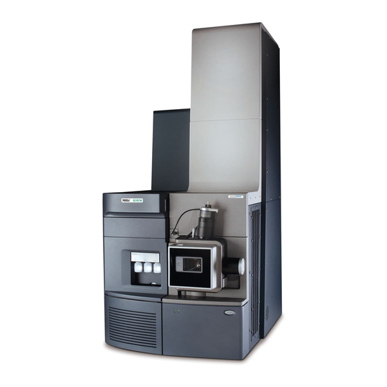
The ACQUITY Xevo G2 QTof UPLC /MS system includes an ACQUITY UPLC system and the Waters Xevo G2 QTof fitted with the LockSpray ESI/APCI/ESCi source. The nanoACQUITY Xevo G2 QTof UPLC/MS system includes a nanoACQUITY UPLC system and the Waters Xevo G2 QTof fitted with the NanoLockSpray source. - Page 22 Waters ACQUITY Xevo G2 QTof UPLC/MS system: Access door to the fluidics valves Sample organizer (optional) Solvent tray Column heater Source interface sliding door Probe High voltage connector for the ESI probe LockSpray source enclosure Xevo G2 QTof Sample manager...
- Page 23 The nanoACQUITY UPLC system includes a binary solvent manager, auxiliary solvent manager, sample manager, column heater, sample organizer, detectors, and a specialized nanoACQUITY UPLC column. Waters informatics software controls the system. For further information, see the nanoACQUITY UPLC System Operator’s Guide or Controlling Contamination in UPLC/MS and HPLC/MS Systems (part number 715001307).
-
Page 24: Software And Data System
Printing data. See the online Help for more information Instrument Console The Instrument Console is an area within the Waters informatics software in which you configure settings, monitor performance, run diagnostic tests, and maintain the mass spectrometer. The instrument console functions independently of the data and does not recognize or control the data software. -
Page 25: Electrospray Ionization (Esi)
Xevo G2 QTof fitted with LockSpray source: Electrospray ionization (ESI) In electrospray ionization (ESI), a strong electrical charge is applied to the eluent as it emerges from a nebulizer. The droplets that compose the resultant aerosol undergo a reduction in size (solvent evaporation). As solvent continues to evaporate, the charge density increases until the droplet surfaces eject ions (ion evaporation). -
Page 26: Atmospheric Pressure Chemical Ionization (Apci)
(in the positive ion mode) or deprotonated (in the negative ion mode). The sample and reagent ions then pass through the sample cone and into the mass spectrometer. Waters Xevo G2 QTof Overview... -
Page 27: Combined Electrospray And Atmospheric Pressure Chemical Ionization (Esci)
Combined electrospray and atmospheric pressure chemical ionization (ESCi) In combined electrospray and atmospheric pressure chemical ionization © (ESCi ) mode, the standard ESI probe is used in conjunction with a corona pin, to allow alternating acquisition of ESI and APCI ionization data, facilitating high-throughput processing and wider compound coverage. - Page 28 Xevo G2 QTof fitted with NanoLockSpray source: The following options are available for the spraying capillary: • Universal NanoFlow™ nebulizer sprayer. This option, for flow injection or coupling to nanoACQUITY, uses a pump to regulate the flow rate as low as 100 nL/min.
-
Page 29: Combined Appi/Apci Source
You can operate the source in APPI or dual-mode, which switches rapidly between ionization modes, facilitating high-throughput analyses. For further details, see the Waters APPI Source Operator’s Guide Supplement. IntelliStart Fluidics system The IntelliStart Fluidics system is built into the instrument; it controls how sample is delivered to the source. -
Page 30: Intellistart Fluidics System Physical Layout
Lock-spray selector valve Access doors Tube guides Flow sensor Grounded union Sample selector valve Divert valve W at er s W at er s Lock-spray pump Sample pump Sample reservoir bottles (A, B and C) 1-12 Waters Xevo G2 QTof Overview... -
Page 31: System Operation
The IntelliStart Fluidics system consists of these components: • A sample delivery system, with a pump, sample selector valve, and diverter valve used for LC and probe connections. • A lock-spray system, with a pump capable of ultra-low flow rates, a lock-spray selector valve, flow sensor, and grounded union. -
Page 32: Ion Optics
The signal from the detector is amplified, digitized, and sent to the software. Ion optics overview: Flight tube Lock-spray sprayer Reflectron Sample sprayer Quadrupole DRE lens Sample cone Isolation valve Hexapole T-Wave collision cell Pusher Detector Transfer lenses 1-14 Waters Xevo G2 QTof Overview... -
Page 33: Leak Sensors
1.5 mL of accumulated leaked liquid in its surrounding reservoir. At the same time, the Instrument Console displays an error message alerting you that a leak has developed. See Waters ACQUITY UPLC Leak Sensor maintenance instructions (part number 71500082506) for complete details. - Page 34 1-16 Waters Xevo G2 QTof Overview...
-
Page 35: Preparing The Mass Spectrometer For Operation
Preparing the Mass Spectrometer for Operation This chapter explains how to start up and shut down the mass spectrometer. Contents: Topic Page Starting the mass spectrometer Preparing the IntelliStart Fluidics system Rebooting the mass spectrometer Leaving the mass spectrometer ready for operation Emergency shutdown of the mass spectrometer... -
Page 36: Starting The Mass Spectrometer
Starting the mass spectrometer The Waters Xevo G2 QTof is compatible with the ACQUITY UPLC and nanoACQUITY UPLC systems. If you are not using either system, refer to the documentation relevant to your LC system (see “Software and data system” on page 1-6). -
Page 37: Verifying The Instrument's State Of Readiness
Allow 4 minutes for the embedded PC to initialize. The power and status LEDs change as follows: Tip: • During initialization, the binary solvent manager’s and sample manager’s status LED flashes green. • After the instruments are successfully powered-on, all power LEDs show steady green. -
Page 38: Flow Rates For The Xevo G2 Qtof System
Flow rates for the Xevo G2 QTof system The Xevo G2 QTof system can run at high flow rates. To optimize desolvation, and thus sensitivity, run the system at appropriate gas flows and desolvation temperatures. Flow rate versus temperature and gas flow:... - Page 39 To install the reservoir bottles: The reservoir bottles can be contaminated with Warning: biohazardous and/or toxic materials. Always wear chemical-resistant, powder-free gloves while performing this procedure. Remove the reservoir bottle caps. Screw the reservoir bottles onto the mass spectrometer, as shown below. Reservoir bottle Solvent delivery tube For each reservoir bottle, ensure that the ends of the solvent delivery...
- Page 40 To install the low-volume vials The reservoir bottles can be contaminated with Warning: biohazardous and/or toxic materials. Always wear chemical-resistant, powder-free gloves while performing this procedure. If a standard reservoir bottle is fitted, remove it. Screw the low-volume adaptors into the manifold and finger-tighten them.
-
Page 41: Adjusting The Solvent Delivery Tube Positions
Adjusting the solvent delivery tube positions For correct operation of the IntelliStart Fluidics system, you must adjust each solvent delivery tube so that its end is close to, but does not, touch, the bottom of the reservoir bottle or low volume vial. To adjust the position of a solvent delivery tube: Open the access door to the fluidics pump (see the figure on page... -
Page 42: Purging The Pump
Purging the pump Whenever you replace a solution bottle, purge the pump with the solution that you are going to use next. See the mass spectrometer’s online Help for details. Ensure that the end of the tubing is fully submerged in the Requirement: solvent in the wash reservoir. -
Page 43: Emergency Shutdown Of The Mass Spectrometer
Emergency shutdown of the mass spectrometer To shut down the mass spectrometer in an emergency: To isolate the instrument from the electrical supply, Warning: disconnect the power cable from the instrument’s rear panel. Data can be lost during an emergency shutdown. Caution: Switch off the power at the electrical outlet. - Page 44 2-10 Preparing the Mass Spectrometer for Operation...
-
Page 45: Configuring The Lockspray Source
Configuring the LockSpray Source This chapter explains how to configure the LockSpray source for the following ionization modes: • ESI (electrospray ionization) • APCI (atmospheric pressure ionization) • ESCi (combined electrospray and atmospheric pressure ionization) Contents: Topic Page Configuring the LockSpray source Configuring for ESI mode Installing the small-bore capillary option Configuring for APCI mode... -
Page 46: Configuring The Lockspray Source
If you intend using the small-bore capillary option, fit the capillary to the probe first (see page 3-7). For more information on using ESI mode, see the Xevo G2 QTof system online Help. Installing the ESI probe Required materials •... - Page 47 To install the ESI probe: The LC system connections, ESI probe, and source can Warning: be contaminated with biohazardous and/or toxic materials. Always wear chemical-resistant, powder-free gloves while performing this procedure. To avoid electric shock, ensure that the instrument is Warning: prepared for working on the source before commencing this procedure.
- Page 48 ESI probe, mounted on the LockSpray source enclosure: Vernier probe adjuster ESI probe Probe locking ring ESI probe cable Vertical probe High voltage connector adjuster Source window Source enclosure release TP03128 To avoid nitrogen leakage, fully tighten the probe locking Caution: ring.
- Page 49 Diverter valve Tubing connection ESI probe Probe adjuster assembly To reduce peak broadening, use 0.004-inch ID tubing Recommendation: for sample flow rates 1.2 mL/min; use 0.005-inch ID tubing for sample flow rates >1.2 mL/min. Requirements: • If you are replacing the tubing supplied with the instrument, you must minimize the length of the tube connecting the diverter valve to the ESI probe.
-
Page 50: Removing The Esi Probe
Removing the ESI probe Required materials Chemical-resistant, powder-free gloves To remove the ESI probe: The LC system connections, ESI probe, and source can Warning: be contaminated with biohazardous and/or toxic materials. Always wear chemical-resistant, powder-free gloves while performing this procedure. To avoid electric shock, ensure that the instrument is Warning: prepared for working on the source before commencing this procedure. -
Page 51: Installing The Small-Bore Capillary Option
Installing the small-bore capillary option Use the small-bore capillary option with 300-µm UPLC columns in systems running at typical flow rates of 10 µL/min. The materials necessary to install the option are supplied in kit form. To avoid damage from excessive pressure, do not exceed flow Caution: rates of 50 µL/min through the ESI probe when the small-bore capillary is fitted. - Page 52 To install the capillary: The probe and source components can be contaminated Warning: with biohazardous and/or toxic materials. Always wear chemical-resistant, powder-free gloves while performing this procedure. The ESI probe tip is sharp. To avoid puncture wounds, handle Warning: the probe with care. Remove the existing capillary (see page 5-66).
- Page 53 Using the needle-nose pliers, slide the UNF coupler, PTFE liner sleeve, and a ferrule onto the capillary. Ferrule UNF coupler PTFE liner sleeve Insert the capillary in the PEEK union, and ensure that it is fully seated. Screw the UNF coupling into the PEEK union, finger-tight only. Gently tug on the capillary, testing to ensure that it stays in place.
- Page 54 To avoid eye injury from high-pressure liquid jet spray, Warning: wear safety goggles when performing the leak test. 12. Test for leaks by attaching the free end of the PEEK tubing to an LC pump and pumping mobile phase through it, at 200 µL/min. •...
- Page 55 19. Fit a new, metal gasket to the probe tip. Metal gasket 20. Fit the probe tip over the capillary, and screw the tip onto the probe assembly. To avoid gas leakage, fully tighten the probe tip. Caution: 21. Use the 10-mm wrench to tighten the probe tip. 10-mm wrench Probe tip Installing the small-bore capillary option...
- Page 56 22. Using the nebulizer adjuster knob, adjust the capillary so that it protrudes by approximately 0.5 mm from the end of the probe tip. During normal operation, the adjuster knob relies on gas pressure Tip: to retract the capillary. To retract the capillary without gas connected, invert the probe and use gravity.
-
Page 57: Configuring For Apci Mode
Configuring for APCI mode To operate in APCI mode, you must fit the APCI probe and corona pin to the LockSpray source enclosure. For more information on using APCI mode, see the Xevo G2 QTof system online Help. Installing the APCI probe Required materials •... - Page 58 To install the APCI probe: The LC system connections, APCI probe, and source can Warning: be contaminated with biohazardous and/or toxic materials. Always wear chemical-resistant, powder-free gloves while performing this procedure. To avoid electric shock, ensure that the instrument is Warning: prepared for working on the source before commencing this procedure.
- Page 59 Tighten the probe locking ring to secure the probe in place. An automatic pressure test is performed when the probe is correctly Tip: seated in position. APCI probe mounted on the source enclosure: Vernier probe adjuster APCI probe Probe locking ring Vertical probe adjuster Source window...
- Page 60 Diverter valve Tubing connection APCI probe Probe adjuster assembly To reduce peak broadening, use 0.004-inch ID tubing Recommendation: for sample flow rates 1.2 mL/min; use 0.005-inch ID tubing for sample flow rates >1.2 mL/min. Requirements: • If you are replacing the tubing supplied with the instrument, you must minimize the length of the tube connecting the diverter valve to the ESI probe.
-
Page 61: Removing The Apci Probe
Ensure that the tubing does not become trapped when Caution: closing the access door to the IntelliStart Fluidics system. Close the access door to the IntelliStart Fluidics system. Install the corona pin in the source (see page 5-11). Removing the APCI probe Required materials Chemical-resistant, powder-free gloves To remove the APCI probe:... -
Page 62: Configuring For Esci Mode
ESI and ESCi modes, facilitating data acquisition in ESI and ESCi modes in parallel. For more information on using dual ESI and ESCi modes, see the Xevo G2 QTof system online Help. “Installing the ESI probe” on page 3-2, “Installing the corona pin in the... -
Page 63: Configuring The Nanolockspray Source
Configuring the NanoLockSpray Source The Waters NanoLockSpray dual, electrospray, ion source enables the optimized co-introduction of sample and lock mass compound directly into the ion source. This feature provides authenticated, exact-mass measurement in MS mode at low flow rates. Contents:... -
Page 64: Overview Of The Nanolockspray Source
Overview of the NanoLockSpray source NanoLockSpray source: Lock mass inlet Camera Camera focussing ring Z-position adjuster Sprayer safety cover X-position adjuster Thumbscrew (on left-hand side of sprayer platform) Sprayer platform adjuster assembly Y-position adjuster Thumbscrew The NanoLockSpray source enclosure holds two nanospray probes positioned orthogonally with respect to one another. -
Page 65: Sample Sprayer
Schematic of the NanoLockSpray source: Lock-spray inlet Sample inlet Baffle Sample cone Spray indexing permits acquiring sample and lock-spray data in separate data channels, and the baffle design ensures negligible cross talk between the two sprays. Data from the lock-spray are used to calculate a correction factor for the mass scale calibration, which is then applied to the sample data to provide exact mass information. -
Page 66: Nanoflow Gas Supply
The Universal NanoFlow sprayer is installed as standard equipment on the NanoLockSpray source. For installation and maintenance details, see the Waters Universal NanoFlow Sprayer Installation and Maintenance Guide (part number 71500110107). Connect the UPLC column directly to the universal sprayer. -
Page 67: Source Type Selection
To avoid electrical shock when working with capillary Warning: electrophoresis (CE) equipment, connect a CE interlock from the rear of the instrument to the CE apparatus (see page B-20). NanoLockSpray source configuration: Sprayer type Used for Universal NanoFlow nebulizer Flow injection or for coupling to sprayer nanoACQUITY with regulated flow rates down to 100 nL/min. -
Page 68: Advancing And Retracting The Sprayer Platform
Advancing and retracting the sprayer platform To move the sprayer platform out of the source: To avoid electrical shock, ensure the safety cover is in place Warning: over the sprayer. Confirm that the sprayer’s safety cover is installed (see the figure on page 4-2). -
Page 69: Adjusting The Sprayer Tip Position
Adjusting the sprayer tip position To adjust the tip position: Adjust the X, Y, and Z controls on the adjuster assembly to move the sprayer tip close to the sampling cone and baffle. Adjust the height of the sprayer so that its tip is level with the center of the baffle. -
Page 70: Setting Up The Camera
Setting up the camera To set up the camera: In the instrument console, ensure that the NanoFlow source is selected. Open the camera control, see the online help for details. Camera Control view of sprayers and sample cone: Sample cone Baffle Sample spray Rotate the camera’s focusing ring to focus on the sample sprayer (see the... -
Page 71: Optional Glass Capillary Sprayer
Optional glass capillary sprayer The glass capillary sprayer is designed for use with metal-coated borosilicate glass capillaries. They allow extremely low flow rates (less than 100 nL/min). The glass capillaries are used for one sample only and must then be discarded. To use the glass capillary sprayer, complete the following procedures: •... -
Page 72: Installing The Glass Capillary Sprayer
Thread the indicated length of PTFE tubing through each of the “finger-tight” nuts, and tighten them into the tee piece in the arrangement as shown. 0.023-inch ID, 120-mm tubing Pressure controller Sprayer 0.006-inch ID, 500-mm tubing 0.006-inch ID, 30-mm tubing Using the SealTight nut and ferrule, connect the 0.023-inch ID PTFE tubing to the pressure controller connection on the base of the source. -
Page 73: Fitting And Loading The Glass Capillary
Retract the sprayer platform adjuster assembly from the source (see page 4-6). Remove the sprayer’s safety cover. Place the sprayer (with gas line fitted) on the platform, and secure it with the thumbscrew. Refit the safety cover. Fitting and loading the glass capillary Required materials •... - Page 74 To avoid injury with a sliver of glass Warning: contaminated with toxic samples, do not touch the sharp end of the capillary. The capillaries are extremely fragile. Handle them with Caution: great care from their square-cut ends. Touching their sharp end can render the needle inoperable.
- Page 75 Load sample into the capillary using either a fused silica syringe needle or a GELoader tip. Shake the loaded capillary to move the liquid to the tip of the Tip: sprayer. With the sprayer mounted on the adjuster platform, screw the union back into the assembly;...
- Page 76 While watching the camera image, carefully move the tip forward toward the groove, until it touches, and a small piece of the glass capillary shears off. Groove Glass capillary Return the sprayer to its previous position. Ascertain that sample is flowing by observing a droplet on the tip. If you cannot observe a droplet, increase the pressure briefly, up to Tip: a maximum of 1.5 bar, and then return the pressure to 0.3 bar.
-
Page 77: Maintenance Procedures
Maintenance Procedures This chapter provides the maintenance guidelines and procedures necessary to maintain the instrument’s performance. Keep to a maintenance schedule, and perform maintenance as required and described in this chapter. Contents: Topic Page Maintenance schedule Spare parts Troubleshooting with Connections INSIGHT Safety and handling Preparing the instrument for working on the source Removal and refitting of the source enclosure... - Page 78 Contents: (Continued) Topic Page Replacing the ESI probe sample capillary 5-66 Cleaning the APCI probe tip 5-75 Replacing the APCI probe sample capillary 5-75 Replacing the reference probe capillary (LockSpray source) 5-82 Replacing the reference probe capillary (NanoLockSpray source) 5-85 Cleaning or replacing the corona pin 5-90 Replacing the APCI probe heater...
-
Page 79: Maintenance Schedule
Maintenance schedule The following table lists periodic maintenance schedules that ensure optimum instrument performance. Maintenance schedule: Procedure Frequency For information... Clean the instrument case. As required. page 5-17. Empty the nitrogen exhaust Check daily, empty as page 5-18. trap bottle. required. -
Page 80: Spare Parts
IntelliStart Fluidics system components. Spare parts Waters recommends that you replace only the parts mentioned in this document. For spare parts details, see the Waters Quality Parts Locator on the Waters Web site’s Services/Support page. Maintenance Procedures... -
Page 81: Troubleshooting With Connections Insight
Connections INSIGHT is an “intelligent” device management (IDM) Web service that enables Waters to provide proactive service and support for the ACQUITY UPLC system. To use Connections INSIGHT, you must install its service agent software on your MassLynx™ workstation. In a client/server system, the service agent must also be installed on the computer from which you control the system. -
Page 82: Safety And Handling
Safety and handling Bear in mind the following safety considerations when performing maintenance procedures: The instrument components can be contaminated with Warning: biohazardous and/or toxic materials. Always wear chemical-resistant, powder-free gloves while handling the components. To prevent injury, always observe Good Laboratory Practice Warning: when handling solvents, changing tubing, or operating the instrument. -
Page 83: Preparing The Instrument For Working On The Source
Preparing the instrument for working on the source For safety reasons, you must follow the procedure described below before working on the source (for example, when changing the probe, installing or removing the corona pin, operating the source isolation valve, and when maintaining the source). - Page 84 To remove the source enclosure: The source components can be contaminated with Warning: biohazardous and/or toxic materials. Always wear chemical-resistant, powder-free gloves while performing this procedure. Prepare the instrument for working on the source (see page 5-7). The probe and source can be hot. To avoid burn injuries, Warning: take great care while working with these components.
- Page 85 Using both hands, grasp the source enclosure, and lift it vertically off the two supporting studs on the source adaptor housing. Cable storage positions Supporting stud TP03164 Source enclosure Store the cables neatly by plugging them into the cable-storage positions on the rear of the source enclosure.
-
Page 86: Fitting The Source Enclosure To The Instrument
Fitting the source enclosure to the instrument Required materials Chemical-resistant, powder-free gloves To fit the source enclosure to the instrument: The source components can be contaminated with Warning: biohazardous and/or toxic materials. Always wear chemical-resistant, powder-free gloves while performing this procedure. -
Page 87: Installing And Removing The Corona Pin
Installing and removing the corona pin For APCI, ESCi, and dual-mode APPI/APCI operation, you must fit a corona pin to the source. Installing the corona pin in the source Required materials Chemical-resistant, powder-free gloves To install the corona pin in the source: The LC system connections, ESI probe, and source can Warning: be contaminated with biohazardous and/or toxic materials. - Page 88 Corona pin mounting contact: Corona pin mounting contact blanking plug TP03130 The corona pin tip is sharp. To avoid puncture wounds, Warning: handle it with care. Fit the corona pin to the corona pin mounting contact, ensuring that the corona pin is securely mounted and that its tip aligns with the sample cone orifice.
-
Page 89: Removing The Corona Pin From The Source
Close the source enclosure. Look through the source window, and use the vernier probe adjuster (see page 3-4) to position the ESI probe tip so that it is pointing, approximately, midway between the tips of the sample cone and corona pin. -
Page 90: Operating The Source Isolation Valve
Operating the source isolation valve You must close the source isolation valve to isolate the source from the instrument vacuum system for certain maintenance procedures. Required materials Chemical-resistant, powder-free gloves To close the source isolation valve before starting a maintenance procedure: The source components can be contaminated with Warning:... - Page 91 Close the source isolation valve by moving its handle counterclockwise, to the vertical position. Isolation valve handle in closed position TP03130 Operating the source isolation valve 5-15...
- Page 92 To open the source isolation valve after completing a maintenance procedure: The source components can be contaminated with Warning: biohazardous and/or toxic materials. Always wear chemical-resistant, powder-free gloves while performing this procedure. To avoid puncture wounds, take great care while working with Warning: the source enclosure open if one or both of these conditions apply: •...
-
Page 93: Removing O-Rings And Seals
Removing O-rings and seals When performing certain maintenance procedures, you must remove O-rings or seals from instrument components. An O-ring removal kit is provided with the instrument. O-ring removal kit: Tool 1 Tool 2 To remove an O-ring: When removing an O-ring or seal from a component, be careful Caution: not to scratch the component with the removal tool. -
Page 94: Emptying The Nitrogen Exhaust Trap Bottle
Emptying the nitrogen exhaust trap bottle Inspect the nitrogen exhaust trap bottle in the instrument exhaust line daily, and empty it before it is more than approximately 10% full. Nitrogen exhaust trap bottle: From instrument To laboratory pilot valve port exhaust port From instrument exhaust connection... - Page 95 Required materials Chemical-resistant, powder-free gloves To empty the nitrogen exhaust trap bottle: In the Instrument Console, click Stop Flow Pull the source enclosure release (located at the bottom, right-hand side) outwards, and swing open the enclosure. The waste liquid in the nitrogen exhaust trap Warning: bottle comprises ACQUITY UPLC solvents and analytes.
-
Page 96: Inspecting The Varian Roughing Pump Oil Level
Inspecting the Varian roughing pump oil level This procedure is not required for an Edwards oil-free roughing pump Note: To ensure correct operation of the roughing pump, do not Caution: operate the pump with the oil level outside the range shown by the oil level sight glass minimum and maximum oil level indicators. -
Page 97: Adding Oil To The Varian Roughing Pump
Adding oil to the Varian roughing pump This procedure is not required for an Edwards oil-free roughing pump. Note: If, on checking the pump’s oil level, you find it low, you must add oil (see page 5-20). Varian roughing pump: Oil filler plug Oil level sight glass TP03159... - Page 98 To add oil to the roughing pump: Vent and shut down the mass spectrometer (see the mass spectrometer’s online Help for details). To avoid personal injury, as well as damage to the Warning: roughing pumps and mass spectrometer, disconnect the power cords for the mass spectrometer and roughing pumps from the main power source.
-
Page 99: Replacing The Varian Roughing Pump's Oil And Oil Mist Filter
Connect the power cords for the mass spectrometer and roughing pump to the main power source. Start the mass spectrometer (see page 2-2). After you add oil to the pump, the following situations can occur: Tips: • The oil level drops slightly during the first month of operation. •... -
Page 100: Replacing The Oil Mist Filter
Allow the roughing pump to cool. The roughing pump oil can be contaminated with Warning: analyte accumulated during normal operation. Always wear chemical-resistant, powder-free gloves when adding or replacing oil. To avoid burn injuries, take great care while working Warning: with the roughing pump: it can be hot. - Page 101 To replace the oil mist filter: The oil mist filter and canister components can be Warning: contaminated with analyte accumulated during normal operation. Always wear chemical-resistant, powder-free gloves when performing this procedure. Use the 3-mm Allen wrench to remove the 4 screws securing the oil mist canister cover to the oil mist canister.
-
Page 102: To Fill The Pump With Oil
Remove the spring and oil mist filter from the canister. The oil mist filter can be contaminated with Warning: biohazardous and/or toxic materials. Dispose of it according to local environmental regulations. Dispose of the oil mist filter in accordance with local environmental regulations. - Page 103 Filling the pump with oil: The roughing pump components can be contaminated Warning: with analyte accumulated during normal operation. Always wear chemical-resistant, powder-free gloves when performing this procedure. To avoid oil leakage when fitting the oil drain plug to the Caution: roughing pump, •...
-
Page 104: Cleaning The Source Components
Connect the power cords for the mass spectrometer and roughing pump to the main power source. Start the mass spectrometer (see page 2-2). After you add oil to the pump, the following situations can occur: Tip: • The oil level drops slightly during the first month of operation. •... -
Page 105: Cleaning The Sampling Cone Assembly
Cleaning the sampling cone assembly You can remove the sampling cone assembly (comprising the sample cone, O-ring, and cone gas nozzle) for cleaning without venting the instrument. Removing the sampling cone assembly from the source Required materials Chemical-resistant, powder-free gloves To remove the sampling cone assembly from the source: The source components can be contaminated with Warning:... - Page 106 Sampling cone assembly Cone gas nozzle handle TP03131 Do not open the isolation valve at any time when the Caution: sampling cone assembly has been removed from the ion block assembly. Slide the sampling cone assembly out of the ion block assembly. Ion block assembly TP03132 5-30...
-
Page 107: Disassembling The Sampling Cone Assembly
Disassembling the sampling cone assembly Required materials • Chemical-resistant, powder-free gloves • Combined 2.5-mm Allen wrench and cone extraction tool To disassemble the sampling cone assembly: The sampling cone assembly can be contaminated with Warning: biohazardous and/or toxic materials. Always wear chemical-resistant, powder-free gloves while performing this procedure. - Page 108 Slide the collar to the end of the tool. Collar Insert the collar in the sample cone. 5-32 Maintenance Procedures...
- Page 109 The sample cone is fragile. Never place it on its tip; Caution: always place it on its flanged base. Rotate and lift the tool and collar to remove the sample cone from the cone gas nozzle. Remove the O-ring from the sample cone. Cone gas nozzle Sample cone Cone gas nozzle...
-
Page 110: Cleaning The Sample Cone And Cone Gas Nozzle
Cleaning the sample cone and cone gas nozzle Required materials • Chemical-resistant, powder-free gloves. • Appropriately sized glass vessels in which to completely immerse components when cleaning. Use only glassware not previously cleaned with surfactants. • HPLC-grade (or better) methanol. •... - Page 111 If you used formic acid in the cleaning solution, do as follows: Rinse the components by immersing them in separate glass vessels containing water and then placing the vessels in the ultrasonic bath for 20 minutes. Remove any residual water from the components by immersing them in separate glass vessels containing methanol and then placing the vessels in the ultrasonic bath for 10 minutes.
-
Page 112: Assembling The Sampling Cone Assembly
Assembling the sampling cone assembly Required materials Chemical-resistant, powder-free gloves To assemble the sampling cone assembly: Caution: • To avoid recontaminating the sampling cone assembly, wear clean chemical-resistant, powder-free gloves during this procedure. • The sample cone is fragile. Never place it on its tip; always place it on its flanged base. - Page 113 To fit the sampling cone assembly to the source: The source components can be contaminated with Warning: biohazardous and/or toxic materials. Always wear chemical-resistant, powder-free gloves while performing this procedure. To avoid puncture wounds, take great care while working with Warning: the source enclosure open if one or both of these conditions apply: •...
-
Page 114: Cleaning The Extraction Cone
Grasp the cone gas nozzle handle, and use it to rotate the sampling cone assembly 90 degrees, moving the handle downward from the horizontal to the vertical position. Open the source isolation valve (see page 5-16). Close the source enclosure. Cleaning the extraction cone Clean the ion block and extraction cone if cleaning the sample cone and cone gas nozzle fails to increase signal sensitivity. - Page 115 The source can be hot. To avoid burn injuries, allow it to Warning: cool for at least 30 minutes before proceeding. To avoid puncture wounds, take great care while Warning: working with the source enclosure open if one or both of these conditions apply: •...
- Page 116 Remove the ion block assembly from the PEEK ion block support. PEEK ion block support Ion block assembly TP03130 5-40 Maintenance Procedures...
-
Page 117: Removing The Extraction Cone From The Ion Block
Removing the extraction cone from the ion block Required materials • Chemical-resistant, powder-free gloves • Combined 2.5-mm Allen wrench and cone extraction tool To remove the extraction cone from the ion block: The ion block components can be contaminated with Warning: biohazardous and/or toxic materials. -
Page 118: Cleaning The Extraction Cone
Caution: • Take great care not to damage the extraction cone aperture when removing the extraction cone from the ion block. • The extraction cone is fragile. Never place it on its tip; always place it on its flanged base. Remove the extraction cone from the ion block. - Page 119 • Ultrasonic bath. • Source of oil-free, inert gas (for example, nitrogen) for drying (air-drying optional). • Wash bottle containing HPLC-grade (or better) 1:1 methanol/water. • Large beaker. To clean the extraction cone: The extraction cone can be contaminated with Warning: biohazardous and/or toxic materials.
-
Page 120: Fitting The Extraction Cone To The Ion Block
Inspect the extraction cone for persisting contamination. If contamination is present, do as follows: Use the wash bottle containing 1:1 methanol/water to rinse the extraction cone over the large beaker. Blow dry the extraction cone with inert, oil-free gas. The extraction cone can be contaminated with Warning: biohazardous and/or toxic materials. -
Page 121: Fitting The Ion Block Assembly To The Source Assembly
Fitting the ion block assembly to the source assembly Required materials • Chemical-resistant, powder-free gloves • Combined 2.5-mm Allen wrench and cone extraction tool To fit the ion block assembly to the source assembly: The source components can be contaminated with Warning: biohazardous and/or toxic materials. -
Page 122: Cleaning The Ion Block Assembly
Cleaning the ion block assembly Clean the ion block assembly if cleaning the sample cone, cone gas nozzle, and extraction cone fails to increase signal sensitivity. Disassembling the source ion block assembly Required materials • Chemical-resistant, powder-free gloves • Combined 2.5-mm Allen wrench and cone extraction tool •... - Page 123 Grasp the cone gas nozzle handle and use it to rotate the sampling cone assembly through 90 degrees. To ensure correct operation of the ion block assembly Caution: after reassembly, • do not remove the sampling cone assembly retaining blocks. •...
- Page 124 Grasp the isolation valve and pull it out of the ion block. Isolation valve O-ring Use the O-ring removal kit to carefully remove the isolation valve O-ring (see page 5-17). The isolation valve O-ring can be contaminated Warning: with biohazardous and/or toxic materials. Dispose of it according to local environmental regulations.
- Page 125 PEEK terminal block securing screw To avoid damaging the heater cartridge assembly wires, Caution: do not bend or twist them when removing the assembly from the ion block. 11. Use the needle-nose pliers to grasp the PEEK terminal block and partially lift it out of the ion block.
- Page 126 13. Use the O-ring removal kit to carefully remove the cover seal from the ion block (see page 5-17). Cover seal Cone gas O-ring 14. Use the O-ring removal kit to carefully remove the cone gas O-ring from the ion block. The cover seal and cone gas O-ring can be Warning: contaminated with biohazardous and/or toxic materials.
- Page 127 16. Insert the combined 2.5-mm Allen wrench and cone extraction tool through the hole in the ion block blanking plug, and then unscrew and remove the ion block blanking plug and associated O-ring. Blanking plug Combined 2.5-mm Allen wrench and cone extraction tool The blanking plug seal can be contaminated with Warning: biohazardous and/or toxic materials.
- Page 128 18. Use the combined 2.5-mm Allen wrench and cone extraction tool to remove the captive screws securing the 2 PEEK extraction cone retainer clips. Securing screw Retainer clip Extraction cone Caution: • Take great care not to damage the extraction cone aperture when removing the extraction cone from the ion block.
-
Page 129: Cleaning The Ion Block Components
20. Remove the extraction cone handle insulator from the extraction cone handle. 21. Remove the extraction cone seal from the ion block. Extraction cone seal Cleaning the ion block components Required materials • Chemical-resistant, powder-free gloves. • Appropriately sized glass vessels in which to completely immerse components when cleaning. - Page 130 To clean the ion block components: The ion block components can be contaminated with Warning: biohazardous and/or toxic materials. Always wear chemical-resistant, powder-free gloves while performing this procedure. Formic acid is extremely corrosive and toxic. Work with Warning: extreme care, use a fume hood and suitable protective equipment. Immerse the ion block and isolation valve in separate glass vessels containing 1:1 methanol/water.
-
Page 131: Assembling The Source Ion Block Assembly
The components can be contaminated with Warning: biohazardous and/or toxic materials. Dispose of them according to local environmental regulations. Inspect each component for persisting contamination. If contamination is present, repeat the cleaning Requirement: procedure. If contamination persists, dispose of the component, and obtain a new one before reassembling the ion block assembly. - Page 132 Use the combined 2.5-mm Allen wrench and cone extraction tool to tighten the captive screw securing each extraction cone retainer clip to the ion block. Fit the blanking plug O-ring (a new one, if you disposed of the old O-ring) to the ion block blanking plug. Fit the blanking plug to the ion block and finger-tighten it.
-
Page 133: Cleaning The Source Hexapole Assembly
17. Hold the sampling cone assembly so that the cone gas nozzle handle is oriented horizontally and at the top, and then slide the sampling cone assembly into the ion block assembly. 18. Grasp the sampling cone assembly handle, and use it to rotate the sampling cone assembly through 90 degrees. - Page 134 Use the 3-mm Allen wrench to unscrew and remove the 4 screws securing the PEEK ion block support to the adaptor housing. Adaptor housing PEEK ion block support Hexapole assembly Securing screws Remove the PEEK ion block support from the adaptor housing. Use the O-ring removal kit to carefully remove all the O-rings from the PEEK ion block support (see page...
-
Page 135: Cleaning The Hexapole Assembly
Cleaning the hexapole assembly Required materials • Chemical-resistant, powder-free gloves. • 500-mL measuring cylinder or appropriately sized glass vessel in which to completely immerse the hexapole when cleaning. Use only glassware not previously cleaned with surfactants. ® • Length of small diameter PEEK or Teflon tubing appropriately sized for suspending the hexapole in the glass vessel when cleaning. - Page 136 To avoid vibration damage to the hexapole assembly, Caution: ensure that the bottom of the assembly is not in contact with the bottom of the glass vessel. Use the hook to carefully suspend the hexapole assembly in the glass vessel so that the bottom of the assembly does not touch the bottom of the vessel.
-
Page 137: Fitting The Hexapole Assembly, Peek Ion Block Support, And Ion Block Assembly To The Source Assembly
Inspect the hexapole assembly for persisting contamination, If contamination is present, do as follows: Requirement: Use the wash bottle containing methanol to rinse the source hexapole assembly over the large beaker. Blow dry the hexapole assembly with inert, oil-free gas. Use the small flat-blade screwdriver to ensure that the hexapole assembly screws are tight. - Page 138 If contamination is present, use 1:1 methanol/water, applied to a Tip: lint-free cloth, to carefully clean the grooves. Fit the O-rings to the PEEK ion block support. Fit new O-rings if any of the old O-rings were disposed of. Requirement: To fit an O-ring in its groove, start fitting the O-ring at the notch in Tip: the groove, and then progressively work the ring into the groove in...
-
Page 139: Replacing The Esi Probe Tip And Gasket
Replacing the ESI probe tip and gasket Replace the ESI probe tip if a blockage occurs in the internal metal sheathing through which the stainless steel capillary passes or if the probe tip is damaged. Removing the ESI probe tip and gasket Required materials •... - Page 140 Remove the ESI probe from the source (see page 3-6). Use the 10-mm wrench to remove the probe tip. 10-mm wrench Probe tip If the probe tip is difficult to remove, use the 7-mm wrench in Tip: conjunction with the 10-mm wrench. 7-mm wrench 10-mm wrench Probe tip...
-
Page 141: Fitting The Esi Probe Tip And Gasket
Remove the metal gasket from the probe tip. Metal gasket The probe tip and metal gasket can be Warning: contaminated with biohazardous and/or toxic materials. Dispose of them according to local environmental regulations. Dispose of the metal gasket in accordance with local environmental regulations. -
Page 142: Replacing The Esi Probe Sample Capillary
To fit the ESI probe tip and gasket: The probe and source components can be contaminated Warning: with biohazardous and/or toxic materials. Always wear chemical-resistant, powder-free gloves while performing this procedure. The ESI probe tip is sharp. To avoid puncture wounds, handle Warning: the probe with care. - Page 143 To remove the existing capillary: The probe and source components can be contaminated Warning: with biohazardous and/or toxic materials. Always wear chemical-resistant, powder-free gloves while performing this procedure. The probe and source can be hot. To avoid burn injuries, take Warning: great care while performing this procedure.
- Page 144 Remove the end cover and gasket from the probe assembly. Nebulizer adjuster knob Gasket End-cover Unscrew and remove the nebulizer adjuster knob. 5-68 Maintenance Procedures...
- Page 145 Use the 10-mm wrench to remove the probe tip. 10-mm wrench Probe tip If the probe tip is difficult to remove, use the 7-mm wrench in Tip: conjunction with the 10-mm wrench. 7-mm wrench 10-mm wrench Probe tip Replacing the ESI probe sample capillary 5-69...
- Page 146 Remove the metal gasket from the probe tip. Metal gasket Remove the PEEK union/UNF coupling assembly and capillary from the probe. PEEK union/UNF coupling assembly Capillary Unscrew and remove the knurled collar from the UNF coupling. PEEK union UNF coupling Locknut Knurled collar Conductive sleeve...
-
Page 147: Installing The New Capillary
11. Unscrew the finger-tight PEEK union from the UNF coupling. Ferrule PTFE liner sleeve 12. Remove the ferrule and PTFE liner sleeve from the capillary. 13. Remove the capillary from the UNF coupling. The capillary, PTFE liner sleeve, and ferrule can Warning: be contaminated with biohazardous and/or toxic materials. - Page 148 • Metal gasket for the probe tip • Sharp knife or PEEK tubing cutter • Safety goggles To install the new capillary: The probe and source components can be contaminated Warning: with biohazardous and/or toxic materials. Always wear chemical-resistant, powder-free gloves while performing this procedure.
- Page 149 Use the needle-nose pliers to slide a new liner sleeve and ferrule onto the capillary. Insert the capillary in the PEEK union, and ensure that it is fully seated. Screw the UNF coupling into the PEEK union, finger-tight only. Gently tug on the capillary, testing to ensure that it stays in place. Use the 7-mm wrench to tighten the locknut against the PEEK union until the union can no longer be twisted.
- Page 150 15. Carefully push the PEEK union/UNF coupling assembly and capillary into the probe assembly so that the locating pin on the UNF coupling is fully engaged in the locating slot at the head of the probe assembly. UNF coupling locating pin Probe assembly locating slot 16.
-
Page 151: Cleaning The Apci Probe Tip
Clean the APCI probe tip when you detect buffer buildup on the probe tip or when the signal intensity weakens. To clean the APCI probe tip: On the Instrument Console system tree, click Xevo G2 QTof > Manual optimization. On the manual optimization page, click to stop the liquid flow. - Page 152 To remove the existing capillary: The probe and source components can be contaminated Warning: with biohazardous and/or toxic materials. Always wear chemical-resistant, powder-free gloves while performing this procedure. The probe and source can be hot. To avoid burn injuries, take Warning: great care while performing this procedure.
- Page 153 Remove the end cover and gasket. Nebulizer adjuster knob Gasket End cover Unscrew and remove the nebulizer adjuster knob. Remove the PEEK union/UNF coupling assembly and capillary from the probe. PEEK union/UNF coupling assembly Capillary Locknut Use the 7-mm wrench to loosen the locknut. Replacing the APCI probe sample capillary 5-77...
-
Page 154: Installing The New Capillary
Unscrew the finger-tight PEEK union from the UNF coupling. Ferrule Remove the ferrule from the capillary. Remove the capillary from the UNF coupling. The capillary and ferrule can be contaminated Warning: with biohazardous and/or toxic materials. Dispose of them according to local environmental regulations. 10. - Page 155 To install the new capillary: The probe and source components can be contaminated Warning: with biohazardous and/or toxic materials. Always wear chemical-resistant, powder-free gloves while performing this procedure. Use the sharp knife or PEEK tubing cutter to cut an approximately 60-cm (24-inches) length of red PEEK tubing.
- Page 156 Use the 7-mm wrench to tighten the locknut against the PEEK union. To avoid high-pressure liquid jet spray, wear safety Warning: goggles when performing the leak test. Perform a leak test by attaching the free end of the PEEK tubing to an LC pump and pumping 50:50 acetonitrile/water through it, at 1 mL/min.
- Page 157 18. Use the combined 2.5-mm Allen wrench and cone extraction tool to fit and tighten the 3 end-cover securing screws. Caution: • When handling the probe heater, take great care to grip the heater so as not to damage its electrical wiring. •...
-
Page 158: Replacing The Reference Probe Capillary (Lockspray Source)
Replacing the reference probe capillary (LockSpray source) Replace the reference probe capillary if it becomes blocked, and you cannot clear it, or if it becomes contaminated or damaged. When replacing the reference probe capillary, you can also replace the microfilter. The microfilter is provided, with manufacturer’s instructions for fitting it, in the spares kit for the reference probe assembly. - Page 159 To remove the existing capillary: Prepare the instrument for working on the source (see page 5-7). The probe and source can be hot. To avoid burn injuries, Warning: take great care while working with these components. The ESI probe tip is sharp. To avoid puncture wounds, if Warning: an ESI probe is fitted to the source, remove the probe before continuing with this procedure.
-
Page 160: Installing The New Capillary
Unscrew the finger-tight nut on the rear of the reference sprayer assembly. Remove the liner tubing and capillary from the reference sprayer assembly. 10. Remove the capillary from the liner tubing. The capillary can be contaminated with Warning: biohazardous and/or toxic materials. Dispose of it according to local environmental regulations. -
Page 161: Replacing The Reference Probe Capillary (Nanolockspray Source)
Rotate the reference sprayer assembly 90º counterclockwise to lock it in place. To prevent pressure from forcing the tubing from the Caution: inside of the source enclosure, firmly tighten the SealTight nut. Use the extender tool to tighten the SealTight nut on the inside of the source enclosure. - Page 162 To remove the reference probe: All plumbing connections, the probe, and the source can Warning: be contaminated with biohazardous and/or toxic materials. Always wear chemical-resistant, powder-free gloves while performing this procedure. To avoid electric shock, ensure that the instrument is Warning: prepared for working on the source before commencing this procedure.
- Page 163 Unscrew the TaperTip PEEK coupler, and remove the TaperTip from the union. Fused-silica capillary with PEEK protective sleeve PEEK couplers TaperTip Fused-silica capillary Union Union retaining screw Unscrew the capillary PEEK coupler, and remove the fused-silica capillary from the union. Where appropriate, remove the protective PEEK sleeve from the fused-silica capillary for reuse.
-
Page 164: Installing The New Tapertip And Capillary
Installing the new TaperTip and capillary Required materials • Chemical-resistant, powder-free gloves • Combined 2.5-mm Allen wrench and cone extraction tool • Fused-silica cutting tool • Pin-plug capillary locator • TaperTip • A 375-mm length of 25-µL, fused-silica capillary, sleeved for protection by 0.015-inch ID PEEK tubing To install the new TaperTip and capillary: On the reference probe assembly, screw the... - Page 165 Locate the PEEK coupler in the union, and carefully slide the fused-silica capillary into the union until it butts against the pin-plug capillary locator. The pin-plug capillary locator correctly locates the capillary Rationale: in the union and ensures a minimum dead volume when fitting the TaperTip.
-
Page 166: Cleaning Or Replacing The Corona Pin
Cleaning or replacing the corona pin Required materials • Chemical-resistant, powder-free gloves • Needle-nose pliers • HPLC-grade (or better) methanol • Lint-free tissue • Lapping film • Corona pin To clean or replace the corona pin: The probe and source components can be contaminated Warning: with biohazardous and/or toxic materials. -
Page 167: Replacing The Apci Probe Heater
Replacing the APCI probe heater Replace the APCI probe heater it fails to heat the probe. Removing the APCI probe heater Required materials Chemical-resistant, powder-free gloves To remove the APCI probe heater: The probe and source components can be contaminated Warning: with biohazardous and/or toxic materials. - Page 168 To avoid damaging the probe heater’s electrical Caution: connections, do not twist the heater when removing it from the probe assembly. Gripping the probe heater as shown, carefully pull it off the probe assembly. Probe heater The probe heater can be contaminated with Warning: biohazardous and/or toxic materials.
-
Page 169: Fitting The New Apci Probe Heater
Fitting the new APCI probe heater Required materials • Chemical-resistant, powder-free gloves • APCI probe heater To fit the new APCI probe heater: Take great care not to damage the probe heater’s Caution: electrical connections, capillary sleeve, or capillary when fitting the heater over the capillary sleeve. -
Page 170: Replacing The Ion Block Source Heater
Replacing the ion block source heater Replace the ion block source heater if it fails to heat the ion block when the instrument is pumped-down (evacuated). Required materials • Chemical-resistant, powder-free gloves • Needle-nose pliers • Combined 2.5-mm Allen wrench and cone extraction tool •... - Page 171 Use the combined 2.5-mm Allen wrench and cone extraction tool to loosen the 2 captive screws securing the ion block cover plate. Ion block cover plate securing screw Ion block cover plate Remove the ion block cover plate. Use the combined 2.5-mm Allen wrench and cone extraction tool to remove the 2 screws securing the heater wires to the PEEK terminal block.
- Page 172 Use the needle-nose pliers to carefully swing the ring terminal tags out of the terminal block. Ring terminal tag Use the needle-nose pliers to gently grasp the heat-shrink tubing on the heater cartridge assembly and slide the assembly out of the ion block. Heat-shrink tubing Heater cartridge assembly 5-96...
- Page 173 The heater cartridge can be contaminated with Warning: biohazardous and/or toxic materials. Dispose of it according to local environmental regulations. Dispose of the heater cartridge assembly. To avoid damaging the heater cartridge assembly wires, Caution: do not bend or twist them when fitting the assembly to the ion block.
-
Page 174: Replacing The Lockspray Source's Assembly Seals
Replacing the LockSpray source’s assembly seals You do not need to replace the NanoLockSpray source’s assembly seals; Note: this section relates to the LockSpray source only. To avoid excessive leakage of solvent vapor into the laboratory atmosphere, the following seals must be renewed at intervals of no greater than 1 year: •... - Page 175 Probe adjuster nebulizer gas seal Probe adjuster assembly probe seal Use the O-ring removal kit to carefully remove the following seals from the source enclosure: • Source enclosure seal • Nebulizer gas seal • Desolvation gas seal Replacing the LockSpray source’s assembly seals 5-99...
-
Page 176: Fitting The New Source Enclosure And Probe Adjuster Assembly Probe Seals
Nebulizer gas seal Desolvation gas seal Source enclosure seal The seals can be contaminated with biohazardous Warning: and/or toxic materials. Dispose of them according to local environmental regulations. Dispose of all the seals in accordance with local environmental regulations. Fitting the new source enclosure and probe adjuster assembly probe seals Required materials •... - Page 177 To fit the new source enclosure and probe adjuster assembly probe seals: The source components can be contaminated with Warning: biohazardous and/or toxic materials. Always wear chemical-resistant, powder-free gloves while performing this procedure. Ensure that all the grooves for seals are free from dirt and debris. If contamination is present, use 1:1 methanol/water, applied to a Tip: lint-free cloth, to carefully clean the grooves.
-
Page 178: Replacing The Mass Spectrometer's Air Filters
Replacing the mass spectrometer’s air filters Replacing the air filter inside the front door Required materials • Needle-nose pliers • New filter To replace the air filter inside the front door: Open the access door to the fluidics pump (see the figure on page 1-4). - Page 179 Remove the filter cover from the instrument. Filter Filter cover Lift the filter, vertically, from its slot in the instrument. If necessary, use the needle-nose pliers to grasp the filter. Tip: Dispose of the filter. Fit the new filter into the instrument. Fit the filter cover to the instrument.
-
Page 180: Replacing The Air Filters On The Sides Of The Instrument
Replacing the air filters on the sides of the instrument Air filters are located on both sides of the instrument. These filters are retained by louvered panels, which you must remove to access the filters. Filter panel on the right-hand side of the instrument: Two similar, smaller panels are located on the left-hand side of the Note: instrument. - Page 181 Required materials ® • M4 POZIDRIV screwdriver • New filters To replace the air filters on the sides of the instrument: For each filter: Use the M4 POZIDRIV screwdriver to remove the screws securing the louvered panel to the instrument enclosure. Remove the louvered panel from the instrument enclosure.
-
Page 182: Replacing The Intellistart Fluidics Tubing
Replacing the IntelliStart Fluidics tubing You must replace the tubing between the components of the IntelliStart Fluidics system when the tubing or its connections become blocked. The following procedures explain how to replace the tubing for the lock-spray and sample delivery systems. They do not, however, address probe connections, which vary according to your application. -
Page 183: Removing The Intellistart Fluidics Tubing
Removing the IntelliStart Fluidics tubing This procedure explains how to remove the IntelliStart Fluidics tubing and disconnect the probe tubing at the diverter valve or grounded union. Required materials Chemical-resistant, powder-free gloves To remove the tubing: All tubing and fittings can be contaminated with Warning: biohazardous and/or toxic materials. -
Page 184: Plumbing The Intellistart Fluidics Lock-Spray System
Plumbing the IntelliStart Fluidics lock-spray system This section explains how to plumb the lock-spray system. Tubing schematic for the lock-spray system: From external Flow sensor From wash bottle reference bottle (optional) reference probe Grounded union Tubing guides Lock-spray selector valve Waste port From pump... - Page 185 Required materials • Chemical-resistant, powder-free gloves. • The Xevo G2 QTof Fluidics Tubing and Fitting Kit. This kit contains components for both the sample and lock-spray Tip: system plumbing. • For the LockSpray reference probe connection – 375 mm of 0.005-inch ID red PEEK –...
- Page 186 Lock-spray selector valve Lock-spray pump Wa ters PEEK nut, Super Flangeless ferrule, and stainless steel (SS) ring: PEEK nut Super Flangeless ferrule Stainless steel ring Long “finger-tight” fitting: Using a long “finger-tight” fitting, connect orange, 1/16-inch, 680-mm, PEEK tubing from port 1 of the lock-spray selector valve, through tubing guide A and into reservoir bottle A.
- Page 187 ate rs Reservoir bottle A As the tubing emerges from the tubing guide, thread a Requirement: long “finger-tight” fitting over it. Push the tubing through the left-hand hole, to the bottom of the reservoir bottle, and tighten the fitting. Follow these suggestions if you find threading the tubing through Tips: the guides difficult: •...
- Page 188 Using a long “finger-tight” fitting, connect orange, 1/16-inch, 680-mm, PEEK tubing from port 3 of the lock-spray selector valve selector valve through tubing guide C and into reservoir bottle C. As the tubing emerges from the tubing guide, thread the Requirement: long “finger-tight”...
- Page 189 Using a long “finger-tight” PEEK nut and 1/32-inch PEEK ferrule, connect the red, 1/32-inch, 200-mm, PEEK tubing from port 4 of the lock-spray selector valve to the left-hand side of the flow sensor, where you use the 1/32-inch, 6-40 Valco™ compression fitting assembly. The narrower, 1/32-inch tubing can slip out of the port.
- Page 190 Using a 1/32-inch, Valco component fitting assembly, connect the red, 1/32-inch, 60-mm, PEEK tubing between the flow sensor and the grounded union, where you use a use a short “finger-tight” nut and 1/32-inch ferrule. Grounded union Wa ters Short “finger-tight” nut and 1/32-inch ferrule: 5-114 Maintenance Procedures...
- Page 191 To avoid electric shock, do not use stainless steel tubing Warning: to connect the grounded union to the reference probe. 10. Connect the grounded union to the source’s reference probe. • For the LockSpray source, use 1/16-inch PEEK tubing connected as follows: –...
-
Page 192: Plumbing The Intellistart Fluidics Sample Delivery System
Plumbing the IntelliStart Fluidics sample delivery system This section explains how to plumb the sample delivery system for standard flow applications. For low flow, nanoACQUITY applications, the column outlet passes directly to the NanoFlow sprayer, bypassing the IntelliStart Fluidics system. IntelliStart Fluidics sample delivery tubing schematic: From wash bottle Sample selector valve... - Page 193 Required materials • Chemical-resistant, powder-free gloves • The Xevo G2 QTof Fluidics Tubing and Fitting Kit This kit contains components for both the sample and lock-spray Tip: system’s plumbing. • Needle-nose pliers To plumb the analyte system: The IntelliStart Fluidics tubing and fittings can be Warning: contaminated with biohazardous and/or toxic materials.
- Page 194 Slide the PEEK nut, stainless steel ring, and Super Flangeless ferrule over the pump end of the steel tubing. PEEK nut Super Flangeless ferrule Stainless steel tubing Stainless steel ring Insert the tubing in the pump, and tighten the fittings. At the sample selector valve, screw the natural-color PEEK female-to-male adaptor into port 7.
- Page 195 Using a long “finger-tight” fitting, connect 1/16-inch, 1000-mm, natural-colored PEEK tubing to port 1 of the sample selector valve, and thread the tubing into the waste port. Waste port Wa ters Long “finger-tight” fitting: The liquid waste system collects waste without requiring a fitted Tip: connection.
- Page 196 Using a long “finger-tight” fitting, connect orange, 1/16-inch, 680-mm, PEEK tubing from port 4 of the sample selector valve, through tubing guide A and into reservoir bottle A. Tubing guide A Wa ters Reservoir Bottle A As the tubing emerges from the tubing guide, thread the Requirement: long “finger-tight”...
- Page 197 Using two long “finger-tight” fittings, connect the red, 1/16-inch, 200-mm, PEEK tubing from port 3 of the sample selector valve to port 3 of the diverter valve. Diverter valve Wa ters Using a long “finger-tight” fitting, connect 1/16-inch, 1000-mm, natural-colored PEEK tubing to port 4 of the diverter valve, and thread it securely into the waste port.
- Page 198 Connect port 2 of the diverter valve to the source probe, observing the relevant procedure: • For the ESI probe, see page 3-2. • For the APCI probe, see page 3-13. Ensure that the tubing does not become trapped when Caution: you close the access doors to the IntelliStart Fluidics system.
-
Page 199: A Safety Advisories
This appendix presents all the safety symbols and statements that apply to the entire line of Waters products. Contents: Topic... -
Page 200: Warning Symbols
Heed all warnings when you install, repair, and operate Waters instruments. Waters assumes no liability for the failure of those who install, repair, or operate its instruments to comply with any safety precaution. -
Page 201: Specific Warnings
The following warnings can appear in the user manuals of particular instruments and on labels affixed to them or their component parts. Burst warning This warning applies to Waters instruments fitted with nonmetallic tubing. Pressurized nonmetallic, or polymer, tubing can burst. Warning: Observe these precautions when working around such tubing: •... - Page 202 Also ensure a gas-fail connection is connected to the LC system so that the LC solvent flow stops if the nitrogen supply fails. Mass spectrometer shock hazard This warning applies to all Waters mass spectrometers. To avoid electric shock, do not remove the mass spectrometer’s Warning: protective panels.
-
Page 203: Caution Symbol
Biohazard warning This warning applies to Waters instruments that can be used to process material that can contain biohazards: substances that contain biological agents capable of producing harmful effects in humans. Waters instruments and software can be used to analyze or... -
Page 204: Warnings That Apply To All Waters Instruments
Warnings that apply to all Waters instruments When operating this device, follow standard quality-control procedures and the equipment guidelines in this section. Attention: Changes or modifications to this unit not expressly approved by the party responsible for compliance could void the user’s authority to operate the equipment. - Page 205 • Keine Schläuche verwenden, die stark geknickt oder überbeansprucht sind. • Nichtmetallische Schläuche nicht für Tetrahydrofuran (THF) oder konzentrierte Salpeter- oder Schwefelsäure verwenden. • Durch Methylenchlorid und Dimethylsulfoxid können nichtmetallische Schläuche quellen; dadurch wird der Berstdruck des Schlauches erheblich reduziert. Warnings that apply to all Waters instruments...
- Page 206 Attenzione: fare attenzione quando si utilizzano tubi in materiale polimerico sotto pressione: • Indossare sempre occhiali da lavoro protettivi nei pressi di tubi di polimero pressurizzati. • Spegnere tutte le fiamme vive nell'ambiente circostante. • Non utilizzare tubi eccessivamente logorati o piegati. •...
- Page 207 농축 질산 또는 황산과 함께 사용하지 마십시오. • 염화 메틸렌(Methylene chloride) 및 디메틸술폭시드(Dimethyl sulfoxide)는 비금속 튜브를 부풀려 튜브의 파열 압력을 크게 감소시킬 수 있으므로 유의하십시오. 警告:圧力のかかったポリマーチューブを扱うときは、注意してください。 • 加圧されたポリマーチューブの付近では、必ず保護メガネを着用してください。 • 近くにある火を消してください。 • 著しく変形した、または折れ曲がったチューブは使用しないでください。 • 非金属チューブには、テトラヒドロフラン(THF)や高濃度の硝酸または硫酸などを流 さないでください。 • 塩化メチレンやジメチルスルホキシドは、非金属チューブの膨張を引き起こす場合が あり、その場合、チューブは極めて低い圧力で破裂します。 Warnings that apply to all Waters instruments...
- Page 208 Warning: The user shall be made aware that if the equipment is used in a manner not specified by the manufacturer, the protection provided by the equipment may be impaired. Attention: L’utilisateur doit être informé que si le matériel est utilisé d’une façon non spécifiée par le fabricant, la protection assurée par le matériel risque d’être défectueuses.
-
Page 209: Electrical And Handling Symbols
Electrical and handling symbols Electrical symbols These can appear in instrument user manuals and on the instrument’s front or rear panels. Electrical power on Electrical power off Standby Direct current Alternating current Protective conductor terminal Frame, or chassis, terminal Fuse Recycle symbol: Do not dispose in municipal waste. -
Page 210: Handling Symbols
Handling symbols These handling symbols and their associated text can appear on labels affixed to the outer packaging of Waters instrument and component shipments. Keep upright! Keep dry! Fragile! Use no hooks! A-12 Safety Advisories... -
Page 211: B External Connections
The mass spectrometer is heavy. To avoid injury, use Warning: suitable machinery and the supplied harness to lift it. Caution: • Contact Waters Technical Service before moving the instrument. • If you must transport the mass spectrometer, or remove it from service, contact Waters Technical Service for recommended cleaning, flushing, and packaging procedures. -
Page 212: Mass Spectrometer External Wiring And Vacuum Connections
The instrument’s rear panel connectors are shown below. The two switches above the roughing pump connector are for Caution: use by Waters service engineers only; they must be kept in the “up” position at all times. Mass spectrometer rear panel connectors:... -
Page 213: Connecting The Varian Oil-Filled Roughing Pump
NW25 center rings (included in the Xevo™ G2 QTof installation kit) • NW25 clamps (included in the Xevo G2 QTof installation kit) • 12.7-mm clear PVC exhaust tubing (included in the Xevo G2 QTof installation kit) • PVC hose clamps (included in the Xevo G2 QTof installation kit) •... - Page 214 To connect the roughing pump: The pump and its connections can be contaminated Warning: with biohazardous and/or toxic materials. Always wear chemical-resistant, powder-free gloves when performing this procedure. Caution: • To ensure correct operation of the roughing pump, install it within 1 degree of horizontal.
- Page 215 B-12. Route the open end of the exhaust tubing to a suitable exhaust vent. For further information, see the Waters Xevo G2 QTof MS Site Preparation Guide (part number 715001948). To ensure correct operation of the roughing pump, do not...
-
Page 216: Making The Electrical Connections To The Varian Oil-Filled Roughing Pump
Making the electrical connections to the Varian oil-filled roughing pump Roughing pump connections: Xevo G2 QTof rear panel Roughing pump d.c. connector Roughing pump main power connector Roughing pump connector TP03159 To power source To make the electrical connections to the oil-filled roughing pump: Connect the roughing pump power cord to the main power source. -
Page 217: Connecting The Edwards Oil-Free Roughing Pump
7-mm nut driver • Sharp knife • NW25 center rings (included in the Xevo G2 QTof installation kit) • NW25 clamps (included in the Xevo G2 QTof installation kit) • NW40 center rings (included in the Xevo G2 QTof installation kit) •... - Page 218 To connect the oil-free roughing pump: The pump and its connections can be contaminated Warning: with biohazardous and/or toxic materials. Always wear chemical-resistant, powder-free gloves when performing this procedure. Caution: • To ensure correct operation of the roughing pump, install it within 1 degree of horizontal.
- Page 219 “Connecting the nitrogen exhaust line” on page B-12. Route the open end of the exhaust tubing to a suitable exhaust vent. For further information, see the Waters Xevo G2 QTof Site Preparation Guide (part number 715002399). Make the electrical connections to the roughing pump (see page B-10).
-
Page 220: Making The Electrical Connections To The Edwards Oil-Free Roughing Pump
Use the higher of the two connectors. The lower connector is for Tip: delayed backing pump control. Connecting to the nitrogen gas supply Required materials • Chemical-resistant, powder-free gloves • 6-mm (¼-in) PTFE tubing (included in the Xevo G2 QTof Installation Kit) • Nitrogen regulator (not supplied) B-10 External Connections... - Page 221 To connect the nitrogen gas supply: The 6-mm (¼-in) PTFE tubing must not be cut to size; use the Warning: complete 5-m (16-ft) length as supplied. Connect one free end of the 6-mm PTFE tubing to the nitrogen inlet port on the rear of the instrument.
-
Page 222: Connecting To The Collision Cell Gas Supply
Set the argon regulator to 50 kPa (0.5 bar, 7 psi). Connecting the nitrogen exhaust line Required materials • Chemical-resistant, powder-free gloves • Sharp knife • Nitrogen exhaust trap bottle • 4-mm and 12-mm PTFE tubing (included in the Xevo G2 QTof installation kit) B-12 External Connections... - Page 223 To connect the nitrogen exhaust line: Warning: • Biohazardous and/or toxic LC solvents and analytes can be carried in the nitrogen exhaust, which must be vented via the nitrogen exhaust trap bottle and laboratory exhaust system. The laboratory exhaust system must provide a minimum vacuum of 0.20 kPa (2 mbar, 0.03 psi) below atmospheric pressure (negative pressure).
- Page 224 Nitrogen exhaust trap bottle: From instrument To laboratory pilot valve port exhaust port From instrument exhaust connection Nitrogen exhaust trap bottle TP03164 To avoid gas leaks, use the sharp knife to cut the PTFE Caution: tubing squarely (that is, perpendicular to its horizontal axis). Cut a length of 4-mm tubing long enough to connect the instrument to the nitrogen exhaust trap bottle.
-
Page 225: Connecting The Liquid Waste Line
Connect one end of the tubing to the exhaust port on the instrument’s rear panel. Connect the free end of the tubing to the inlet port on the nitrogen exhaust trap bottle. To avoid gas leaks, use the sharp knife to cut the PTFE Caution: tubing squarely (that is, perpendicular to its horizontal axis). - Page 226 Drain cup Barbed fitting Drain line TP02684 To prevent leakage of biohazardous and/or toxic Warning: materials, • do not crimp or bend drain line. A crimp or bend can impede flow to the waste container. • empty the waste container before the lower end of the drain tube is covered by waste solvent.
- Page 227 Positioning of drain tube: Correct Incorrect TP01807 Connecting the liquid waste line B-17...
-
Page 228: Connecting The Epc
Connecting the EPC In addition to a workstation PC or instrument server, the Xevo G2 Tof has an external EPC with a real-time operating system that provides the real-time, data-processing required by the analog-digital controller (ADC). Mass spectrometer rear panel connections to the EPC: ADC Ethernet Instrument LAN External Connections 1... -
Page 229: Connecting The Workstation (Systems With No Acquity Lc)
Connect one end of the shielded, crossover, network cable to the lower of the two Ethernet ports on the EPC. Connect the free end of the shielded, crossover, network cable to the ADC Ethernet port on the instrument. To connect the EPC to the power source: Do not connect the EPC’s power supply cord until you complete Caution: the installation procedures in the previous sections. -
Page 230: Connecting Ethernet Cables (Systems With Acquity Lc)
Connecting Ethernet cables (systems with ACQUITY LC) Use shielded network cables with the mass spectrometer to Requirement: ensure compliance with FCC limits. To make Ethernet connections: Connect one end of one shielded Ethernet cable to the network switch, and then connect the free end to the Ethernet card on the preconfigured ®... - Page 231 Input and output connector locations: Instrument LAN External Connections 1 External connections Service Bus identification tables EPC Com Port EPC Parallel Port External Connections 2 Video Output OUT - External connections 1 External Connections 1 External connections 2 External Connections 2 System Activity Input/output signal connector configuration: Input/output signal connectors...
- Page 232 External connections 1: Function Rating Event In 1+, digital signal, +5 V optimum +3.3V max +5V Event In 1-, digital ground, 0V Not used Event In 2+, digital signal, +5 V optimum +3.3V max +5V Event In 2-, digital ground, 0V Not used Not used CE Interlock Out, common...
-
Page 233: Signal Connections
Signal connections Mass spectrometer signal connections: Signal connections Description Analog Out Used for analog chart output functionality. The output voltage range is 0 to 2 V. The resolution of the voltage output is 12 bits. Gas Fail Interlock Out Used to stop the solvent flow if the nitrogen gas supply fails. - Page 234 To make signal connections: Determine the signal connection location from the silk-screened label on the rear panel of each instrument. Attach the positive and negative leads of the signal cable to the connector. Connector Signal cable TP02585 Slide the clamp (with the bend facing down) into the protective shield. Insert the clamp and shield (with the bend facing down) into the connection cover, and loosely tighten with one self-tapping screw.
- Page 235 Insert the connector with the signal cable into the connection cover, position the clamp over the cable leads, and tighten the clamp into place with the second self-tapping screw. Cable leads Clamp Place the second connection cover over the first cover, and snap it into place.
-
Page 236: Connecting To The Electricity Source
To avoid electrical shock, use the SVT-type power cord in the Warning: United States and HAR-type (or better) in Europe. For information regarding what cord to use in other countries, contact your local Waters distributor. Connect the female end of the power cord to the receptacle on the rear... -
Page 237: Installing The Camera Driver Software
Select Search for the best driver in these locations. Select Include this location in the search and: • For MassLynx™, browse to C:\MassLynx\USBCameraDriver. • For UNIFI™, browse to C:\Program Files\Waters\UNIFI\USBCameraDriver. Click Next. The software installs. Result: Click Finish. Connecting the NanoLockSpray source camera... - Page 238 B-28 External Connections...
-
Page 239: C Materials Of Construction And Compatible Solvents
Materials of Construction and Compatible Solvents To confirm the integrity of the source exhaust Warning: system, you must address any safety issues raised by the contents of this Appendix. Contents: Topic Page Preventing contamination Items exposed to solvent Solvents used to prepare mobile phases... -
Page 240: Preventing Contamination
Preventing contamination For information on preventing contamination, refer to Controlling Contamination in UPLC/MS and HPLC/MS Systems (part number 715001307). You can find this document on http://www.waters.com; click Services and Support > Support. Items exposed to solvent The items that appear in the following table can be exposed to solvent. You must evaluate the safety issues if the solvents used in your application differ from the solvents typically used with these items. -
Page 241: Solvents Used To Prepare Mobile Phases
Items exposed to solvent: (Continued) Item Material Trap bottle Polypropylene Trap bottle push-in fittings Nitrile butadiene rubber, stainless steel, polybutylene terephthalate, and polyoxymethylene APPI lamp drive assembly: Mounting shaft Stainless steel Repeller electrode Stainless steel Insulator PEEK Lamp window Magnesium fluoride Solvents used to prepare mobile phases These solvents are the most common ingredients used to prepare mobile phases for reverse-phase LC/MS (API):... - Page 242 Materials of Construction and Compatible Solvents...
-
Page 243: Index
Index combined 2.5-mm Allen wrench and cone extraction tool 5-31 ACQUITY UPLC system combined APPI/APCI source APCI mode 3-13 3-18 compliant solvents APCI probe cone gas nozzle, cleaning 5-34 cleaning tip 5-75 connecting installing 3-13 Edwards roughing pump removing 3-17 electricity source B-26 replacing... - Page 244 ESI mode installing reservoir bottles ESI probe preparing capillary, replacing 5-66 pump, purging installing overview optimizing for ESCi 3-18 IntelliStart Fluidics removing 5-85 reference plumbing 5-108 tip, replacing 5-63 sample plumbing 5-116 Ethernet cables, connecting B-20 intended use external ion block assembly connections cleaning 5-46...
- Page 245 LEDs probes maintenance procedures APCI preparing for working on the source cleaning tip installing 3-13 rebooting removing 3-17 source enclosure replacing capillary removing replacing heater state of readiness, verifying mass spectrometer shock hazard installing materials of construction optimizing for ESCi 3-18 mobile phases, solvents used in removing...
- Page 246 5-23 LockSpray oil mist filter 5-23 configuring roughing pump NanoLockSpray spare parts inspecting level of starting replacing Xevo G2 QTof oil mist filter, replacing status LED symbols caution safety advisories electrical A-11 safety, procedures for maintenance handling A-12 sample cone, cleaning...
- Page 247 Waters Quality Parts Locator workstation, connecting B-19 Xevo G2 QTof calibration emergency shutdown leaving ready for operation LEDs maintenance procedures overview preparing for working on the source rebooting source enclosure, removing state of readiness, verifying Xevo G2 QTof system, flow rates Index-5...
- Page 248 Index-6...
Need help?
Do you have a question about the Xevo G2 QTof and is the answer not in the manual?
Questions and answers