Waters Xevo G2-XS QTof Overview And Maintenance Manual
Hide thumbs
Also See for Xevo G2-XS QTof:
- Overview and maintenance manual (306 pages) ,
- Quick start manual (2 pages)

Related Manuals for Waters Xevo G2-XS QTof


Summary of Contents for Waters Xevo G2-XS QTof
- Page 1 Xevo G2-XS QTof Overview and Maintenance Guide 715004496 Copyright © Waters Corporation 2021 Version 04 (previously released as Rev. D) All rights reserved...
-
Page 2: General Information
This document is believed to be complete and accurate at the time of publication. In no event shall Waters Corporation be liable for incidental or consequential damages in connection with, or arising from, its use. For the most recent revision of this document, consult the Waters website (www.waters.com). -
Page 3: Customer Comments
Contacting Waters Contact Waters with enhancement requests or technical questions regarding the use, transportation, removal, or disposal of any Waters product. You can reach us via the Internet, telephone, fax, or conventional mail. March 31, 2021, 715004496 Ver. 04 (previously released as Rev. D) -
Page 4: Legal Manufacturer
Considerations specific to the device Solvent leakage hazard The source exhaust system is designed to be robust and leak-tight. Waters recommends that you perform a hazard analysis, assuming a maximum leak into the laboratory atmosphere of 10% LC eluate. - Page 5 Warning: To avoid exposure to toxic substances and biohazards from O-ring leaks in the source exhaust system, observe these precautions: • Replace the source O-rings at intervals not exceeding one year. • Prevent chemical degradation of the source O-rings, which can withstand exposure only to certain solvents, by determining whether any solvents you use are chemically compatible with the composition of the O-rings.
- Page 6 Source ion block assembly Source ion block assembly High-voltage hazard Warning: To avoid electric shock, observe these precautions: • Do not remove the mass spectrometer’s protective panels. The components they cover are not user-serviceable. • When the instrument is in Operate mode, avoid touching the areas marked with the high voltage warning symbol.
-
Page 7: Electrical Power Safety Notice
Do not dispose of the instrument or return it to Waters for repair until the authority responsible for approving its removal from the premises specifies the extent of decontamination required and the level of residual contamination permissible. -
Page 8: Operating The Device
For compliance with the Waste Electrical and Electronic Equipment Directive (WEEE) 2012/19/EU, contact Waters Corporation for the correct disposal and recycling instructions For indoor use only March 31, 2021, 715004496 Ver. 04 (previously released as Rev. D) -
Page 9: Audience And Purpose
Intended use of the Xevo G2-XS QTof Waters designed the orthogonal acceleration, time-of-flight Xevo G2-XS QTof for use as a research tool to deliver authenticated mass measurement. The Xevo G2-XS QTof is for research use only and is not intended for use in diagnostic applications. -
Page 10: Equipment Misuse Notice
Analyzing samples from a complex matrix When analyzing samples from a complex matrix such as soil, tissue, serum/plasma, whole blood, and other sources, note that the matrix components can adversely affect LC/MS results, enhancing or suppressing ionization. To minimize these matrix effects, adopt the following measures: •... -
Page 11: Emc Emissions
Class A products are suitable for use in all establishments other than residential locations and those directly connected to a low voltage power supply network supplying a building for domestic purposes. There may be potential difficulties in ensuring electromagnetic compatibility in other environments due to conducted as well as radiated disturbances. -
Page 12: Table Of Contents
Equipment misuse notice....................... vii Safety advisories..........................vii Operating the device..........................viii Applicable symbols........................viii Audience and purpose........................ix Intended use of the Xevo G2-XS QTof.................... ix Calibrating............................ix Quality control..........................ix Equipment misuse notice......................... x EMC considerations..........................x FCC radiation emissions notice....................... x Canada spectrum management emissions notice................ - Page 13 2.1.1 Verifying the instrument's state of readiness................ 38 2.1.2 Monitoring the mass spectrometer LEDs................38 2.1.3 Calibration..........................38 2.1.4 Flow rates for the Xevo G2-XS QTof system................ 38 2.2 Preparing the Fluidics system......................39 2.2.1 Installing the reservoir bottles....................39 2.2.2 Installing the low-volume vials....................40 2.2.3 Adjusting the solvent delivery tube positions................
- Page 14 3.2 Configuring for ESI mode....................... 44 3.2.1 Installing the ESI probe......................44 3.2.2 Removing the ESI probe.......................48 3.3 Configuring for APCI mode......................48 3.3.1 Installing the IonSABRE II probe..................49 3.3.2 Removing the IonSABRE II probe..................51 3.4 Configuring for ESCi mode......................51 3.4.1 Optimizing the ESI probe for ESCi operation................52 4 Configuring the NanoLockSpray source..............53 4.1 Overview of the NanoLockSpray source..................
- Page 15 5.6 Flow rates for the Xevo G2-XS QTof system..................78 6 UniSpray LockSpray source..................79 6.1 Installing the UniSpray source......................81 6.1.1 Installing the UniSpray LockSpray source................81 6.2 Removing the UniSpray source .....................84 6.2.1 Removing the UniSpray LockSpray source................84 7 Maintenance procedures..................86 7.1 Maintenance schedule........................
- Page 16 7.12.3 Adding oil to the roughing pump..................105 7.12.4 Replacing the roughing pump’s oil and oil demister elements..........107 7.13 Cleaning the source components....................113 7.14 Cleaning the sampling cone assembly..................113 7.14.1 Removing the sampling cone assembly from the source..........114 7.14.2 Disassembling the sampling cone assembly..............
- Page 17 7.23 Installing the new reference probe..................... 184 7.24 Replacing the NanoLockSpray reference probe TaperTip emitter or capillary......188 7.24.1 Removing the NanoLockSpray reference probe...............188 7.24.2 Installing the new TaperTip emitter and capillary.............. 190 7.25 Replacing the ionKey reference-probe capillary.................192 7.25.1 Removing the ionKey reference-probe capillary............... 192 7.26 Cleaning or replacing the corona pin..................197 7.27 Maintaining the UniSpray impactor pin..................198 7.27.1 Cleaning or replacing the UniSpray impactor pin..............199...
- Page 18 A.1.1 Specific warnings........................246 A.2 Notices............................247 A.3 Bottles Prohibited symbol......................248 A.4 Required protection........................248 A.5 Warnings that apply to all Waters instruments and devices............248 A.6 Warnings that address the replacement of fuses.................252 A.7 Electrical symbols........................254 A.8 Handling symbols.........................255 B External Connections..................... 256 B.1 Mass spectrometer external wiring and vacuum connections.............
- Page 19 B.13 Connecting the camera for the NanoLockSpray source or ionKey source ....... 280 B.13.1 Installing the camera driver software................281 C Materials of construction and compatible solvents..........282 C.1 Preventing contamination......................282 C.2 Items exposed to solvent......................282 C.3 Solvents used to prepare mobile phases..................283 March 31, 2021, 715004496 Ver.
-
Page 20: Waters Xevo G2-Xs Qtof Overview
1.1 Waters Xevo G2-XS QTof The Xevo G2-XS QTof Mass Spectrometry (MS) system is an orthogonal acceleration, time-of- flight (Tof) mass spectrometer operated by Waters informatics software. Either of the following high-performance, ZSpray, dual-orthogonal API sources is fitted as standard equipment: •... -
Page 21: Acquity Uplc/Ms Xevo G2-Xs Qtof Systems
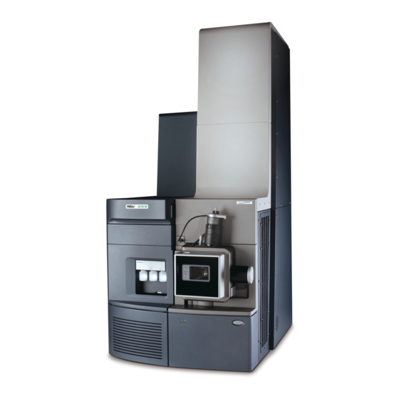
Support > Support Documents and Downloads. In Waters documents, the term “fluidics” refers to the IntelliStart Fluidics system, the instrument’s onboard system that delivers sample and solvent to the probe of the mass spectrometer. It can also denote plumbing components and fluid pathways within and between system modules. - Page 22 1.1.2.2.1 Waters ACQUITY Xevo G2-XS QTof UPLC/MS System Figure 1–1: ACQUITY Xevo G2-XS QTof UPLC/MS system Sample organizer (optional) March 31, 2021, 715004496 Ver. 04 (previously released as Rev. D) Page 22...
- Page 23 The ACQUITY UPLC M-Class system includes a binary solvent manager, an auxiliary solvent manager if present, a sample manager, a column heater, a sample organizer, detectors, and a specialized ACQUITY UPLC M-Class column. Waters informatics software controls the system. For further information, see the ACQUITY UPLC M-Class System Guide (715003588) or Controlling Contamination in LC/MS Systems (715001307).
- Page 24 Figure 1–2: ACQUITY M-Class Xevo G2-XS QTof UPLC/MS system Access door to the fluidics pumps Solvent tray Access door to the fluidics valves Source interface sliding door NanoLockSpray source enclosure Xevo G2-XS QTof µBinary solvent manager µSample manager-fixed loop Trap valve manager Solvent tray March 31, 2021, 715004496 Ver.
-
Page 25: Software And Data System
1.1.3 Software and data system MassLynx or UNIFI software can control the mass spectrometer. See MassLynx software (Page UNIFI software (Page 25) for more information about those applications. Both MassLynx and UNIFI software enable these major operations: • Configuring the system •... -
Page 26: Lockspray Source And Ionization Modes
You can use the LockSpray source with the ESI, APCI, and ESCi ionization modes (see Configuring the LockSpray Source (Page 44)), and with the ASAP ionization mode (see Atmospheric Solids Analysis Probe Operator's Guide Supplement (715002034). Figure 1–3: Xevo G2-XS QTof fitted with LockSpray source Solvent tray LockSpray source 1.2.1 Electrospray ionization (ESI) In ESI, a strong electrical charge is applied to the eluent as it emerges from a nebulizer. -
Page 27: Atmospheric Pressure Chemical Ionization (Apci)
The standard ESI probe capillary accommodates flow rates of up to 2 mL/min, making it suitable for LC applications in the range of 100 µL/min to 2 mL/min. To reduce peak broadening for lower flow rate LC applications, such as 1-mm UPLC columns, use the optional, small-bore capillary, which can accommodate a maximum flow rate of 100 µL/min. -
Page 28: Atmospheric Solids Analysis Probe (Asap)
1.2.4 Atmospheric solids analysis probe (ASAP) The ASAP facilitates rapid analysis of volatile and semivolatile compounds in solids, liquids, and polymers. It is particularly suited to analyzing low-polarity compounds. The ASAP directly replaces the ESI or APCI probe in the instrument’s source housing and has no external gas or electrical connections. -
Page 29: Combined Appi/Apci Source
Figure 1–5: Xevo G2-XS QTof fitted with NanoLockSpray source Solvent tray NanoLockSpray source Options shown in the following table are available for the spraying capillary: Table 1–1: Spraying-capillary options Option Description Universal NanoFlow nebulizer sprayer For flow injection or coupling to nanoACQUITY systems. -
Page 30: Atmospheric Pressure Gas Chromatography (Apgc)
For further details, see the Waters APPI Source Operator’s Guide Supplement (71500137602). 1.5 Atmospheric pressure gas chromatography (APGC) The Waters APGC couples an Agilent GC with the Xevo G2-XS QTof. Doing so enables you to perform LC and GC analyses in the same system without compromising performance. The APGC provides complementary information to the LC/MS instrument, enabling analysis of compounds of low molecular weight and low-to-intermediate polarity. -
Page 31: Intellistart Fluidics System
1.8 IntelliStart fluidics system 1.8.1 Fluidics system overview The IntelliStart Fluidics system is built into the instrument. It controls how sample is delivered to the source. System connections differ according to whether you are using a LockSpray or NanoLockSpray source. See Replacing the IntelliStart fluidics tubing (Page 217). - Page 32 Figure 1–6: IntelliStart Fluidics system components Access doors Tubing guides LockSpray selector valve Optional flow sensor Sample selector valve Grounded union Diverter valve Sample pump Sample reservoir bottles (A, B, and C) LockSpray pump March 31, 2021, 715004496 Ver. 04 (previously released as Rev. D) Page 32...
-
Page 33: System Operation
The IntelliStart fluidics system consists of these components: • A sample delivery system composed of a pump, sample selector valve, and a divert valve used for LC and probe connections. • A LockSpray system, composed of a pump capable of ultra-low flow rates, a LockSpray selector valve, flow sensor, and grounded union. - Page 34 4. The ions pass into the time-of-flight (Tof) analyzer. A high-voltage pulse orthogonally accelerates the ions up the flight tube, where a reflectron reflects them back toward the detector. Ions of different mass-to-charge ratios arrive at the detector at different times. The difference in the arrival times provides the basis for a mass spectrum.
-
Page 35: Leak Sensors
1.5 mL of accumulated leaked liquid in its surrounding reservoir. At the same time, the software displays an error message alerting you that a leak has developed. Consult the Waters ACQUITY UPLC Leak Sensor Maintenance Instructions (71500082506) for complete details. -
Page 36: Preparing The Mass Spectrometer For Operation
3. Power-on the instrument server or workstation PC. 4. On the Xevo G2-XS QTof's rear panel, ensure that the pump switch is in the Auto (up) position and the electronics switch is in the On (up) position (see the figure in... - Page 37 6. Power-on the ACQUITY instruments. Result: Each system instrument runs a series of startup tests. 7. Wait four minutes for the PC to initialize. Tip: The power and status LEDs change as follows: • During initialization, the status LEDs of the binary solvent manager and the sample manager each flash green.
-
Page 38: Verifying The Instrument's State Of Readiness
Calibrate the mass spectrometer prior to use. See the mass spectrometer’s online Help. 2.1.4 Flow rates for the Xevo G2-XS QTof system The Xevo G2-XS QTof system can run at high flow rates. To optimize desolvation and sensitivity, run the system at appropriate gas flows and desolvation temperatures. -
Page 39: Preparing The Fluidics System
Table 2–2: Flow rate versus temperature and gas flow: (continued) Flow rate (mL/min) Source temperature Desolvation Desolvation gas (°C) temperature (°C) flow (L/h) >0.500 1200 2.2 Preparing the Fluidics system For additional information, see IntelliStart fluidics system physical layout (Page 31). -
Page 40: Installing The Low-Volume Vials
Figure 2–1: Installing the reservoir bottles Reservoir bottle Solvent delivery tube 3. For each reservoir bottle, ensure that the ends of the solvent delivery tubes are positioned so that they are close to, but not touching, the bottom of the bottle (see Adjusting the solvent delivery tube positions (Page 41)). -
Page 41: Adjusting The Solvent Delivery Tube Positions
Figure 2–2: Installing the low-volume vials Low-volume adapter Low-volume vial Solvent delivery tube Warning: To avoid laceration injuries caused by the shattering of fragile, low- volume, glass vials, take care when installing them and never use force. 3. Screw the low-volume vials into the adapters. 4. -
Page 42: Purging The Pump
Figure 2–3: Solvent delivery tubes Finger-tight fitting Solvent delivery tube 3. Move the solvent delivery tube so that its end is close to, but does not touch, the bottom of the reservoir bottle or low volume vial. 4. Tighten the finger-tight fitting. 5. -
Page 43: Leaving The Mass Spectrometer Ready For Operation
Note: If you are using UNIFI software, you can leave it running while you reboot the mass spectrometer. 2. Open the sliding door above the instrument’s source enclosure and locate the reset button aperture. 3. Insert a short length of PEEK tubing into the aperture to press the reset button. 2.4 Leaving the mass spectrometer ready for operation When you are not using the instrument, stop the LC flow and put the instrument in Standby mode to conserve energy and reduce nitrogen consumption. -
Page 44: Configuring The Lockspray Source
For more information about using ESI mode, see the Xevo G2-XS QTof system online Help. Note: If you are using a tool-free ESI probe, to install or remove the probe, see the Waters Tool- Free Probe Maintenance Guide Supplement (715005492). - Page 45 • A long, finger-tight fitting • PEEK, finger-tight nut • Ferrule To install the ESI probe: Warning: To avoid personal contamination with biologically hazardous, toxic, and corrosive materials, wear chemical-resistant, powder-free gloves when performing this procedure. Warning: To avoid harmless, static-like electric shock, before you touch any external surfaces marked with the high-voltage warning symbol, ensure that the mass spectrometer is in Standby mode.
- Page 46 Location hole of the probe adjuster assembly Figure 3–2: ESI probe mounted on the source enclosure Vernier probe adjuster ESI probe Source enclosure release Source window ESI high-voltage cable 4. Tighten the probe locking ring to secure the probe in place. Tip: An automatic pressure test is performed when the probe is correctly seated in position.
- Page 47 Figure 3–3: Securing the union Diverter valve Tubing connection ESI probe Probe adjuster assembly Note: To reduce peak broadening, use 0.004-inch ID tubing for sample flow rates ≤1.2 mL/min; use 0.005-inch ID tubing for sample flow rates >1.2 mL/min. Requirements: •...
-
Page 48: Removing The Esi Probe
For more information about using APCI mode, see the Xevo G2-XS QTof system online Help. Note: If you are using a tool-free APCI probe, to install or remove the probe, see the Waters Tool-Free Probe Maintenance Guide Supplement (715005492). March 31, 2021, 715004496 Ver. 04 (previously released as Rev. D) -
Page 49: Installing The Ionsabre Ii Probe
3.3.1 Installing the IonSABRE II probe Required materials • Chemical-resistant, powder-free gloves • Utility knife or PEEK tubing cutter To install the IonSABRE II probe: Warning: To avoid personal contamination with biologically hazardous, toxic, and corrosive materials, wear chemical-resistant, powder-free gloves when performing this procedure. Warning: To avoid harmless, static-like electric shock, before you touch any external surfaces marked with the high-voltage warning symbol, ensure that the mass... - Page 50 Location hole of the probe adjuster assembly 3. Tighten the probe locking ring to secure the probe in place. Tip: An automatic pressure test is performed when the probe is correctly seated in position. Figure 3–7: IonSABRE II probe mounted on the source enclosure Vernier probe adjuster APCI probe Source enclosure release...
-
Page 51: Removing The Ionsabre Ii Probe
• If you are replacing the tubing supplied with the instrument, you must minimize the length of the tube connecting the divert valve to the IonSABRE II probe. Doing so minimizes delays and dispersion. • When cutting the tubing to length, cut it squarely. 6. -
Page 52: Optimizing The Esi Probe For Esci Operation
ESI and ESCi modes, facilitating data acquisition in ESI and ESCi modes in parallel. For more information on using dual ESI and ESCi modes, see the Xevo G2-XS QTof system online Help. 3.4.1 Optimizing the ESI probe for ESCi operation See the mass spectrometer’s online Help for details on how to optimize the ESI probe for ESCi... -
Page 53: Configuring The Nanolockspray Source
4 Configuring the NanoLockSpray source The NanoLockSpray electrospray ion-source enables the optimized co-introduction of sample and lock-mass compound directly into the ion source. At low flow rates, this feature provides authenticated, exact-mass measurement in both MS and MS/MS modes. 4.1 Overview of the NanoLockSpray source Figure 4–1: NanoLockSpray source NanoLockSpray reference probe Camera... - Page 54 Y-position adjuster Thumbscrew Sprayer-platform adjuster assembly Thumbscrew (on left-hand side of sprayer platform) X-position adjuster Sprayer safety cover Clear sprayer shield (fitted) Z-position adjuster LockSpray sprayer inlet The NanoLockSpray source enclosure holds two NanoFlow sprayers positioned orthogonally with respect to one another. The sample flows through one sprayer and the lock mass reference solution through the other.
-
Page 55: Sample Sprayer
LockSpray inlet Spray indexing permits acquisition of sample and LockSpray data in separate data channels, and the baffle design ensures negligible cross-talk between the two sprays. The LockSpray data are used to calculate a correction factor for the mass scale calibration, which is then applied to the sample data, providing exact mass information. -
Page 56: Selecting And Configuring The Nanolockspray Source
4.2 Selecting and configuring the NanoLockSpray source The Universal NanoFlow sprayer is installed as standard equipment on the NanoLockSpray source. For installation and maintenance details, see the Universal NanoFlow Sprayer Installation and Maintenance Guide (71500110107). When fitted, the NanoLockSpray source is automatically recognized by the software. Requirement: The sprayer platform must be inserted in the source enclosure for correct identification of the source. -
Page 57: Moving The Sprayer Platform Into The Source
4.3.2 Moving the sprayer platform into the source To move the sprayer platform into the source: Warning: To avoid harmless, static-like electrical shock, ensure that the safety cover is in place over the sprayer. 1. Confirm that the clear sprayer shield is in place and secured (see Overview of the NanoLockSpray source (Page 53)). - Page 58 To set up the camera: 1. In the mass spectrometer control software, launch the camera software (see the instrument's online Help). • In the UNIFI System Console, click Tools > Nanoflow Camera > Launch. • In the MassLynx Tune window, click Source > ionKey. Note: In a Network deployment, the camera software must be launched on the laboratory network device (LND) attached to the instrument.
-
Page 59: Optional Glass Capillary Sprayer
Sprayer tip Sample sprayer 4.6 Optional glass capillary sprayer The glass-capillary sprayer is designed for use with metal-coated borosilicate glass capillaries. The glass capillaries allow extremely low flow rates (less than 100 nL/min). You only use the glass capillaries for one sample, and then must discard them. To use the glass-capillary sprayer, complete the procedures described in the Borosilicate Glass Capillary Sprayer Operator's Guide Documentation CD (715003371). - Page 60 Figure 4–4: NanoLockSpray sample fluidics delivery tubing schematic LockSpray reservoir NanoFlow sensor Wash Pump line From wash Sample selector valve To reference sprayer Diverter valve Pump line Tube guide Tube guide Note: All tubing is PEEK, except for that comprising the connection between the pump and sample selector valve, which is stainless steel.
- Page 61 Natural 1,000 Required materials • Chemical-resistant, powder-free gloves • Needle-nose pliers • The Xevo G2-XS QTof Fluidics Tubing and Fitting Kit Tip: This kit contains components for both the sample and NanoSpray system’s plumbing. To plumb the analyte system: Warning: To avoid personal contamination with biologically hazardous, toxic, and corrosive materials, wear chemical-resistant, powder-free gloves when performing this procedure.
- Page 62 Figure 4–5: Connecting the sample pump to the sample selector valve Wat ers Sample selector valve Sample pump a. Slide the PEEK nut, stainless steel ring, and Super Flangeless ferrule over the pump end of the steel tubing. Figure 4–6: PEEK nut, stainless steel ring, and Super Flangeless ferrule PEEK nut Super Flangeless ferrule Stainless steel tubing...
- Page 63 Figure 4–7: Fitting the PEEK adapter Flangeless nut Flangeless ferrule PEEK female-to-male adapter d. Slide the transparent, 1/16-inch, flangeless nut and blue, 1/16-inch, flangeless ferrule over the tubing. Rationale: These components provide fail-safe pressure relief in the event of a blockage.
- Page 64 Requirement: Push the tubing to the bottom of the wash solution and secure it so that it cannot float to the surface during use. 5. Using a long, finger-tight fitting, connect orange, 1/16-inch, 680-mm PEEK tubing from port 4 of the sample selector valve through tubing guide A and into reservoir bottle A. Figure 4–10: Connecting the sample selector valve to reservoir bottle A Wat ers Tubing guide A...
- Page 65 Figure 4–11: Connecting the sample selector valve to the divert valve Wat ers Divert valve 8. Using a long, finger-tight fitting, connect 1/16-inch, 1,000-mm, natural-colored PEEK tubing to port 4 of the divert valve and thread it securely into the waste port. Tip: This is the same waste port as that used in step 3.
-
Page 66: Installing And Removing The Ionkey Source
5 Installing and removing the ionKey source 5.1 ionKey source The ionKey source integrates UPLC separation into the source of the mass spectrometer. For a complete description, see ionKey source (Page 30). The following sections explain how to install or remove an ionKey source. For additional information, see the ACQUITY UPLC M-Class System Guide (715003588) and the ionKey/MS System Guide (715004028). - Page 67 Figure 5–1: ionKey source Camera mount iKey locking/unlocking handle Front cover iKey separation device docking port Stop flow button Reference probe (present only for ToF-variant ionKey sources, for use on instruments fitted with a time-of-flight (ToF) mass analyzer) The ionKey source holds the iKey separation device with its integrated emitter positioned orthogonally to the mass spectrometer’s sample cone.
-
Page 68: Installing The Ionkey Source
5.2.1 Installing the ionKey Source Required materials • Chemical-resistant, powder-free gloves • Flat-blade screwdriver • 1/4-inch open-end wrench Warning: To avoid personal contamination with biologically hazardous or toxic compounds, wear clean, chemical-resistant, powder-free gloves when performing this procedure. Warning: To avoid static-like electric shock, ensure that the instrument is prepared for working on the source before starting this procedure. - Page 69 Figure 5–2: IntelliStart Fluidics Thumbscrews Infill panel Onboard fluidics panel 6. Remove the infill panel from the instrument and store it in a safe location. 7. Fit the cable management bracket to the instrument, as follows: a. Position the cable management bracket so that the vertical cutout is aligned with the upper and lower tabs on the instrument.
- Page 70 Figure 5–3: Cable management bracket Cable management bracket Vertical cutout 8. Remove the two thumbscrews from the replacement infill panel provided with the ionKey source. 9. Position the replacement infill panel above the onboard fluidics panel and secure the panels to each other using the thumbscrews you removed. Requirement: Install the thumbscrews with the screw thread uppermost, as shown in the following figure.
- Page 71 Figure 5–4: Infill assembly thumbscrew Infill panel Thumbscrew Onboard fluidics panel 10. Use two hands to fit the ionKey source enclosure to the two supporting studs on the source adapter housing. 11. Swing the source enclosure to the closed position, ensuring that it locks into place. 12.
- Page 72 Figure 5–5: IonKey source connections Data/power cable to PSPI connector on µSample manager High-voltage cable Reference-probe high-voltage cable Options cable Fluid waste line Optional post-column addition (PCA) line Fluid infusion line Fluid inlet line 15. Connect the high-voltage cable (white) to the high-voltage supply outlet on the mass spectrometer.
- Page 73 Figure 5–6: Mass spectrometer connections Reference-probe high-voltage cable (Green) Data/power cable to PSPI connector on µSample manager High-voltage cable (White) Options cable (Blue) 16. Connect the reference-probe high-voltage cable (green) to the reference-probe power inlet on the mass spectrometer. 17. Connect the options cable (blue) to the options port on the mass spectrometer. 18.
- Page 74 Figure 5–7: Fluid-line aperture Aperture closed Aperture open (spring-loaded) Fluid-line aperture Tip: In the following steps, when connecting the fluid lines for the ionKey source, use the cable management bracket to guide the fluid lines. Doing so helps to keep the fluidics plumbing tidy.
-
Page 75: Installing Ionkey Source Software
ACQUITY UPLC M-Class System Guide (715003588). 5.3 Installing ionKey source software If you are installing an ionKey source on your Xevo G2-XS QTof for the first time, you must install the appropriate MassLynx software SCN and the ACQUITY UPLC M-Class driver pack. For further details, see the following documents: March 31, 2021, 715004496 Ver. -
Page 76: Installing The Camera In The Ionkey Source
M-Class cart fitted with an ionKey or universal source holder, you can secure the source enclosure to the holder. Doing so keeps the enclosure close to the Xevo G2-XS QTof, for when it is next needed. Securing the source enclosure also assists with managing the ionKey source’s fluid lines and helps prevent contamination of the fluid lines. - Page 77 See Installing and Using the Universal Source Holder (715004884)for additional information about installing and using the universal source holder on the M-Class cart, and securing the source enclosure to the holder. Recommendation: The ionKey source is installed along with a cable-management bracket and a replacement infill panel.
-
Page 78: Flow Rates For The Xevo G2-Xs Qtof System
13. Carefully remove the ionKey source module and safely store it. 5.6 Flow rates for the Xevo G2-XS QTof system The Xevo G2-XS QTof system can run at high flow rates. To optimize desolvation and sensitivity, run the system at appropriate gas flows and desolvation temperatures. -
Page 79: Unispray Lockspray Source
6 UniSpray LockSpray source The UniSpray source enabled with LockSpray is available for use on Time-of-Flight (ToF) mass spectrometers. Figure 6–1: UniSpray LockSpray source – front view Probe PEEK fitting Probe assembly Vertical probe adjuster Horizontal probe adjuster Baffle-motor housing Source enclosure door release handle LockSpray sample port March 31, 2021, 715004496 Ver. - Page 80 Figure 6–2: UniSpray LockSpray source - rear view Capillary adjuster Impactor pin and LockSpray baffle Cable storage sockets Probe adjuster overflow spur and probe storage clip See also: Topics about maintaining the source components: • Replacing the UniSpray probe assembly (Page 200) •...
-
Page 81: Installing The Unispray Source
6.1 Installing the UniSpray source 6.1.1 Installing the UniSpray LockSpray source Required materials • Chemical-resistant, powder-free gloves Warning: To avoid personal contamination with biologically hazardous, toxic, and corrosive materials, wear chemical-resistant, powder-free gloves when performing this procedure. To install the UniSpray source: 1. - Page 82 Figure 6–3: Fitting the source Supporting studs Source enclosure door release handle 5. Slide open the instrument's source control panel door. 6. Connect the LockSpray high-voltage cable (green) to the LockSpray high-voltage cable socket (green) on the mass spectrometer. March 31, 2021, 715004496 Ver. 04 (previously released as Rev. D) Page 82...
- Page 83 Figure 6–4: UniSpray LockSpray source connections LockSpray high-voltage connector (green) Baffle motor cable (blue) Probe adjuster cable (yellow) Impactor pin high-voltage cable 7. Connect the baffle motor cable (blue) to the baffle motor cable socket (blue) on the mass spectrometer. 8.
-
Page 84: Removing The Unispray Source
10. Screw the probe assembly PEEK fitting into the instrument’s diverter valve port until it is finger-tight. 11. Screw the LockSpray sample tube into the source’s LockSpray sample inlet port until it is finger-tight. 12. Close the source interface door, ensuring that it locks into place. Result: The source pressure test initiates. - Page 85 Figure 6–5: Fitting the UniSpray probe to the storage clip on the source probe adjuster Probe assembly PEEK fitting Probe assembly Storage clip on the overflow spur 3. Swing open the UniSpray source enclosure unit from the source mounting on the mass spectrometer.
-
Page 86: Maintenance Procedures
7 Maintenance procedures This section provides the maintenance guidelines and procedures necessary to maintain the instrument's performance. Keep to a maintenance schedule and perform maintenance as required and described in this section. 7.1 Maintenance schedule The following table lists periodic maintenance schedules that ensure optimum instrument performance. - Page 87 Table 7–1: Maintenance schedule (continued) Procedure Frequency For information... Clean or replace the UniSpray When sensitivity decreases to Maintaining the UniSpray impactor pin. unacceptable levels or sample impactor pin (Page 198). flow is inconsistent. Replace the UniSpray probe When sensitivity decreases to Replacing the UniSpray assembly.
-
Page 88: Spare Parts
(Page 242). 7.2 Spare parts To ensure that your system operates as designed, use only Waters Quality Parts. Visit www.waters.com/wqp for information about Waters Quality Parts, including how to order them. 7.3 Safety and handling Bear in mind the following safety considerations when performing maintenance procedures:... -
Page 89: Preparing The Instrument For Working On The Source
Warning: To avoid injury, ensure that these criteria are met when performing maintenance operations inside the source enclosure: • The instrument is in Standby mode. • LC flow is diverted to waste or set to Off. • Desolvation gas flow is stopped. Notice: To avoid damaging the iKey: •... -
Page 90: Using Masslynx Software To Prepare The Instrument For Operations On Or Inside Its Source
7.4.1 Using MassLynx software to prepare the instrument for operations on or inside its source To use MassLynx software to prepare the instrument for operations on or inside its source: 1. In the Instrument Console, click Standby and confirm that the Operate indicator is not illuminated. -
Page 91: Removing The Source Enclosure From The Instrument
Removing the IonSABRE II probe (Page 51). • If you are removing a tool-free ESI or APCI probe, see the Waters Tool-Free Probe Maintenance Guide Supplement (715005492). 3. Slide open the instrument’s source interface door (see ACQUITY Xevo G2-XS QTof UPLC/MS systems (Page 21)). -
Page 92: Fitting The Source Enclosure To The Instrument
Figure 7–1: Source enclosure mounted on instrument Cable storage positions Supporting stud Source enclosure 7. Store the cables neatly by plugging them into the cable-storage positions on the rear of the source enclosure. 7.5.2 Fitting the source enclosure to the instrument Required materials Chemical-resistant, powder-free gloves To fit the source enclosure to the instrument:... -
Page 93: Installing And Removing The Corona Pin
1. Using both hands, fit the source enclosure to the two supporting studs on the source adaptor housing. Notice: To avoid damaging the sample inlet, when removing a NanoLockSpray source enclosure, you must slide the sprayer platform out of the source enclosure before you open the enclosure. - Page 94 2. Pull the source enclosure release (located at the bottom, right-hand side) outward, and swing open the enclosure. 3. Remove the blanking plug from the corona pin mounting contact. Tip: Store the blanking plug in a safe location. Figure 7–2: Blanking plug fitted to the corona pin mounting contact Corona pin mounting contact blanking plug Warning: To avoid puncture wounds, handle the corona pin with care.
-
Page 95: Removing The Corona Pin From The Source
tip so that it is pointing approximately midway between the tips of the sample cone and the corona pin. 7.6.2 Removing the corona pin from the source Required materials • Chemical-resistant, powder-free gloves To remove the corona pin from the source: Warning: To avoid personal contamination with biologically hazardous, toxic, and corrosive materials, wear chemical-resistant, powder-free gloves when performing this procedure. -
Page 96: Operating The Source Isolation Valve
Figure 7–4: Corona pin Corona pin 4. Fit the blanking plug to the corona pin mounting contact. Figure 7–5: Blanking plug fitted to the corona pin mounting contact Corona pin mounting contact blanking plug 5. Close the source enclosure. 7.7 Operating the source isolation valve You must close the source isolation valve to isolate the source from the instrument vacuum system for certain maintenance procedures. -
Page 97: Closing The Source Isolation Valve
Warning: To avoid personal contamination with biologically hazardous, toxic, or corrosive materials, and to avoid spreading contamination to uncontaminated surfaces, wear clean, chemical-resistant, powder-free gloves when performing this procedure. Warning: To avoid static-like electric shock, ensure that the instrument is prepared for working on the source before starting this procedure. -
Page 98: Opening The Source Isolation Valve
Figure 7–6: Closing the source isolation valve Isolation valve handle in closed position 7.7.2 Opening the source isolation valve To open the source isolation valve after completing a maintenance procedure: Warning: To avoid personal contamination with biologically hazardous, toxic, and corrosive materials, wear chemical-resistant, powder-free gloves when performing this procedure. -
Page 99: Removing O-Rings And Seals
Figure 7–7: Source isolation valve opened Isolation valve handle in open position 2. Close the source enclosure. 7.8 Removing O-rings and seals You must remove O-rings or seals from instrument components when performing certain maintenance procedures. 7.8.1 O-ring removal kit Note: The O-ring removal kit (700005054) is available to order separately. -
Page 100: Cleaning The Instrument Case
To remove an O-ring: Notice: To avoid damaging the component when removing an O-ring or seal from it, ensure that you do not scratch the component with the removal tool. Use the tools as aids to pull the O-ring or seal from its groove. Tip: If you do not plan to reuse the O-ring or seal, you can use the forked end of tool 1 to impale the O-ring or seal to remove it. - Page 101 Figure 7–9: Nitrogen exhaust trap bottle To laboratory exhaust port From instrument pilot valve port Bottle support Nitrogen exhaust trap bottle From instrument exhaust connection One-way valve Required materials Chemical-resistant, powder-free gloves To empty the nitrogen exhaust trap bottle: 1. To stop the LC flow, follow the action specified below, according to your software: March 31, 2021, 715004496 Ver.
-
Page 102: Maintaining The Roughing Pump
Software Action MassLynx In the instrument console, click Stop Flow UNIFI On the System Console tool bar, click Stop Flow 2. Pull the source enclosure release (located at the bottom, right-hand side) outward and swing open the enclosure. Warning: To avoid personal contamination with biologically hazardous, toxic, and corrosive materials, wear chemical-resistant, powder-free gloves when performing this procedure. -
Page 103: Maintaining The Oil-Filled Roughing Pump
Appendix B in this guide. 7.12 Maintaining the oil-filled roughing pump Note: Two models of the oil-filled roughing pump are currently available with Waters instruments. See the following figures to identify the model supplied with your instrument. Requirement: In addition to the roughing pump maintenance requirements detailed here, refer to the manufacturer’s documentation provided with the instrument. -
Page 104: Gas Ballasting The Oil-Filled Roughing Pump
Figure 7–11: Leybold Sogevac oil-filled roughing pump with frequency converter (SV40 BI Gas ballast valve Oil drain Oil level sight glass Oil filler plug 7.12.1 Gas ballasting the oil-filled roughing pump Notice: To avoid shortening oil life and the useful life of the roughing pump, routinely gas ballast the pump. -
Page 105: Inspecting The Roughing Pump Oil Level
To gas ballast the roughing pumps: Warning: To avoid burn injuries, take great care while working with the roughing pump. Notice: To avoid damage: • Do not vent the instrument when the roughing pump is gas ballasting. • Do not gas ballast the roughing pump while the instrument is in Operate mode. •... - Page 106 • Funnel • Leybonol LVO 200 vacuum pump oil To add oil to the roughing pump: 1. Vent and power-down the mass spectrometer (see the mass spectrometer’s online Help for details). Warning: To avoid personal injury, as well as damage to the roughing pump and mass spectrometer, disconnect the power cords for the mass spectrometer and roughing pump from the main power source.
-
Page 107: Replacing The Roughing Pump's Oil And Oil Demister Elements
• The oil level drops slightly during the first month of operation. • The oil changes color (darkens) over time. • After running the pump for 12 to 48 hours, it is common to see a few drops of oil near the filler plug. - Page 108 7.12.4.2 Draining the roughing pump’s oil To drain the roughing pump’s oil: Warning: To avoid personal contamination with biologically hazardous or toxic compounds, wear clean, chemical-resistant, powder-free gloves when performing this procedure. Warning: To avoid burn injuries, exercise care when handling the column or other components heated to high temperatures.
- Page 109 Tip: After you add the oil, the level appearing in the sight glass can be above the maximum indication. This apparent excess does not suggest a problem. During the first few days of operation, the oil level falls to within the normal operating range. 2.
- Page 110 Figure 7–12: Removing the securing bolts Securing bolt Exhaust flange 3. Use the 6-mm hex wrench to remove the four bolts securing the exhaust flange to the roughing pump. 4. Carefully remove the exhaust flange and oil demister element from the roughing pump. Figure 7–13: Removing the exhaust flange and oil demister element Oil demister element 5.
- Page 111 Figure 7–14: Removing the securing nut Spring Securing nut 6. Holding the oil demister element slightly elevated to prevent the loss of the spring, remove the exhaust flange from the oil demister element. Figure 7–15: Removing the exhaust flange 7. Remove the spring from the oil demister element. Warning: To avoid spreading contamination with biologically hazardous, toxic, and corrosive materials, dispose of all waste materials according to local environmental...
- Page 112 7.12.4.5 Fitting the new oil demister element Required materials • Chemical-resistant, powder-free gloves • 6-mm hex wrench • 10-mm open-end wrench To fit the new roughing pump oil demister element: 1. Place the spring onto the new oil demister element. Figure 7–16: Fitting the spring 2.
-
Page 113: Cleaning The Source Components
7.12.4.6 Preparing for operation after changing the roughing pump’s oil and oil demister element To prepare for operation after changing the roughing pump’s oil and oil demister element: 1. Connect the power cords for the mass spectrometer and the roughing pump to the main power source. -
Page 114: Removing The Sampling Cone Assembly From The Source
7.14.1 Removing the sampling cone assembly from the source Required materials Chemical-resistant, powder-free gloves To remove the sampling cone assembly from the source: Warning: To avoid personal contamination with biologically hazardous, toxic, and corrosive materials, wear chemical-resistant, powder-free gloves when performing this procedure. Warning: To avoid harmless, static-like electric shock, before you touch any external surfaces marked with the high-voltage warning symbol, ensure that the mass... -
Page 115: Disassembling The Sampling Cone Assembly
Figure 7–19: Removing the sampling cone assembly Ion block assembly Notice: To avoid damage, do not open the source isolation valve before fitting the sampling cone assembly to the ion block assembly. 7.14.2 Disassembling the sampling cone assembly Required materials •... - Page 116 Figure 7–20: Cone extraction tool location Combined 2.5-mm hex wrench and cone extraction tool 2. Slide the collar to the end of the tool. Figure 7–21: Cone extraction tool Collar 3. Insert the collar in the sample cone. Figure 7–22: Inserting the cone extraction tool Insert the collar Notice: To avoid damaging the sampling cone, which is fragile, do not place it...
- Page 117 Figure 7–23: Removing the sample cone Rotate the tool Remove the sample cone 5. Remove the O-ring from the sample cone. Figure 7–24: O-ring removed from the sample cone Cone gas nozzle Sample cone O-ring Cone gas nozzle handle Warning: To avoid spreading contamination with biologically hazardous, toxic, and corrosive materials, dispose of all waste materials according to local environmental regulations.
-
Page 118: Cleaning The Sample Cone And Cone Gas Nozzle
6. If the O-ring shows signs of deterioration or damage, dispose of it in accordance with local environmental regulations. 7.14.3 Cleaning the sample cone and cone gas nozzle Required materials • Chemical-resistant, powder-free gloves • Appropriately sized glass vessels in which to completely immerse components when cleaning. -
Page 119: Assembling The Sampling Cone Assembly
Note: If you used formic acid in the cleaning solution, proceed to step 4. If not, go to step 4. If you used formic acid in the cleaning solution, do as follows: a. Rinse the components by immersing them in separate glass vessels containing water, and then placing the vessels in the ultrasonic bath for 20 minutes. -
Page 120: Fitting The Sampling Cone Assembly To The Source
Figure 7–25: Sampling cone assembly O-ring Sample cone Cone gas nozzle Cone gas nozzle handle Note: The PEEK handle is removable on earlier models of the cone gas nozzle assembly. If you detached the handle from the cone gas nozzle for cleaning, replace the handle and tighten it. -
Page 121: Cleaning The Ion Block Assembly
Notice: To avoid damage, do not open the source isolation valve before fitting the sampling cone assembly to the ion block assembly. 1. Ensure that the source isolation valve is in the closed position (see Closing the source isolation valve (Page 97)). -
Page 122: Removing The Ion Block Assembly From The Source Assembly
7.15.1 Removing the ion block assembly from the source assembly Required materials • Chemical-resistant, powder-free gloves • Combined 2.5-mm hex wrench and cone extraction tool To remove the ion block assembly: Warning: To avoid personal contamination with biologically hazardous, toxic, and corrosive materials, wear chemical-resistant, powder-free gloves when performing this procedure. -
Page 123: Disassembling The Source Ion Block Assembly
Figure 7–27: The ion block assembly securing screws Ion block assembly securing screws 6. Remove the ion block assembly from the PEEK ion block support. Figure 7–28: Removing the ion block assembly PEEK ion block support Ion block assembly 7.15.2 Disassembling the source ion block assembly Required materials •... - Page 124 To disassemble the ion block assembly: Warning: To avoid personal contamination with biologically hazardous, toxic, and corrosive materials, wear chemical-resistant, powder-free gloves when performing this procedure. 1. Ensure that the source isolation valve is closed. Figure 7–29: Source ion block assembly Source isolation valve handle in closed position Sampling cone assembly retaining blocks Cone gas nozzle handle...
- Page 125 Figure 7–30: Source ion block cover plate Ion block cover plate securing screw Ion block cover plate 5. Remove the ion block cover plate. 6. Grasp the isolation valve and pull it out of the ion block. Figure 7–31: Removing the isolation valve from the ion block Isolation valve O-ring 7.
- Page 126 Warning: To avoid spreading contamination with biologically hazardous, toxic, and corrosive materials, dispose of all waste materials according to local environmental regulations. 8. If the isolation valve O-ring shows signs of deterioration or damage, dispose of it in accordance with local environmental regulations. 9.
- Page 127 Figure 7–33: Removing the PEEK terminal block and ceramic heater mounting block Ceramic heater mounting block PEEK terminal block 11. Use the O-ring removal kit to carefully remove the cover seal from the ion block (see also Removing O-rings and seals (Page 99)).
-
Page 128: Cleaning The Ion Block Components
Warning: To avoid spreading contamination with biologically hazardous, toxic, and corrosive materials, dispose of all waste materials according to local environmental regulations. 13. If the cover seal or cone gas O-ring shows signs of deterioration or damage, dispose of it in accordance with local environmental regulations. -
Page 129: Assembling The Source Ion Block Assembly
a. Rinse the components by immersing them separately in glass vessels containing water, and then placing the vessels in the ultrasonic bath for 20 minutes. b. Remove residual water from the components by immersing them in separate glass vessels containing methanol, and then placing the vessels in the ultrasonic bath for 10 minutes. -
Page 130: Fitting The Ion Block Assembly To The Source Assembly
1. Carefully fit the PEEK terminal block and ceramic heater mounting block, complete with heater cartridge assembly, to the ion block. 2. Use the combined 2.5-mm hex wrench and cone extraction tool to tighten the captive PEEK terminal block securing screw. 3. -
Page 131: Cleaning The Stepwave Ion Guide Assembly
Warning: To avoid puncture wounds, take great care while working with the source enclosure open if one or both of these conditions apply: • An ESI probe is fitted (the probe’s tip is sharp). • A corona pin is fitted (the pin’s tip is sharp). Notice: To avoid recontaminating the components, wear clean, chemical-resistant, powder-free gloves. - Page 132 To remove the ion block support from the source assembly: Warning: To avoid personal contamination with biologically hazardous, toxic, and corrosive materials, wear chemical-resistant, powder-free gloves when performing this procedure. 1. Remove the source enclosure from the instrument (see Removing and refitting the source enclosure (Page 90)).
-
Page 133: Removing The Stepwave Assembly From The Source Assembly
6. If any of the O-rings show signs of deterioration or damage, dispose of them in accordance with local environmental regulations. 7.16.3 Removing the StepWave assembly from the source assembly Required materials • Chemical-resistant, powder-free gloves • Seal-breaker and locator tool •... - Page 134 Figure 7–36: Seal breaker and locator tool Handle March 31, 2021, 715004496 Ver. 04 (previously released as Rev. D) Page 134...
- Page 135 Figure 7–37: Seal breaker and locator tool positioned on the adapter housing Adapter housing Ion guide cap Seal breaker and locator tool 2. Push firmly on the seal breaker and locator tool’s handle to lever the StepWave assembly slightly out of the adapter housing. Rationale: Moving the assembly in this manner releases it from a seal located inside the instrument.
- Page 136 Figure 7–38: StepWave assembly removal and insertion tool StepWave assembly removal and insertion tool Cutout Ion block support screw holes Brown PEEK ion guide cap Pins Slot Notice: To avoid damage when removing the StepWave ion guide assembly from the adapter housing, handle only the brown PEEK ion guide cap. 4.
-
Page 137: Disassembling The Stepwave Ion Guide Assembly
Rationale: Fitting and closing the source enclosure prevents debris from entering the instrument while you are working on the StepWave ion guide assembly. 7.16.4 Disassembling the StepWave ion guide assembly Warning: To avoid personal contamination with biologically hazardous, toxic, and corrosive materials, wear chemical-resistant, powder-free gloves when performing this procedure. - Page 138 Figure 7–40: StepWave ion guide assembly separated First ion guide assembly Second ion guide assembly 3. Remove the brown PEEK gasket from the second ion guide assembly. Figure 7–41: StepWave second ion guide assembly Second ion guide assembly Brown PEEK gasket 4.
-
Page 139: Cleaning The Stepwave Ion Guide Assembly
Figure 7–42: StepWave second ion guide assembly Differential pumping aperture O-ring Second ion guide assembly Warning: To avoid spreading contamination with biologically hazardous, toxic, and corrosive materials, dispose of all waste materials according to local environmental regulations. 5. If the O-ring shows signs of deterioration or damage, dispose of it in accordance with local environmental regulations. - Page 140 Figure 7–43: Cleaning the first ion guide PCB assembly First ion guide PCB assembly Hook 3. Add Waters MS Cleaning Solution to the glass vessel until the first ion guide PCB assembly is immersed completely. March 31, 2021, 715004496 Ver. 04 (previously released as Rev. D)
- Page 141 4. Repeat step 1 through step 3 for the second ion guide PCB assembly, placing the hook through one of the support rod holes. Figure 7–44: Cleaning the second ion guide PCB assembly Hook Second ion guide PCB assembly 5. Place the vessels containing the first ion guide and second ion guide PCB assemblies in the ultrasonic bath for 20 minutes.
-
Page 142: Assembling The Stepwave Ion Guide Assembly
15. Carefully remove each ion guide PCB assembly from its vessel and blow-dry each assembly using inert, oil-free gas. 16. Discard the used isopropyl alcohol using an appropriate waste container. 7.16.6 Assembling the StepWave ion guide assembly Required materials • Chemical-resistant, powder-free gloves •... -
Page 143: Fitting The Stepwave Assembly To The Source Assembly
Figure 7–46: Fitting the brown PEEK gasket Brown PEEK gasket Second ion guide assembly 3. Align the first ion guide assembly with the second ion guide assembly. 4. Use the combined, 2.5-mm, hex wrench and cone extraction tool to fit and tighten the two screws securing the first ion guide assembly to the second ion guide assembly. - Page 144 Tip: The StepWave assembly can only be inserted in the correct orientation in the StepWave removal and insertion tool. Figure 7–47: Sliding the StepWave assembly into the StepWave removal and insertion tool StepWave assembly removal and insertion tool StepWave assembly Pins Cutout 4.
-
Page 145: Fitting The Ion Block Support To The Source
Figure 7–48: Fitting the seal breaker and locator tool StepWave assembly Adapter housing Inverted seal breaker and locator tool 8. Push firmly on the seal breaker and locator tool until the tool’s face contacts the adapter housing. Rationale: This fully locates the StepWave assembly in the adapter housing. 9. -
Page 146: Maintaining The Esi Probe
7.17 Maintaining the ESI probe Maintaining the ESI probe involves replacing the following components of the probe when required. Note: To maintain a tool-free ESI probe, see the Waters Tool-Free Probe Maintenance Guide Supplement (715005492). Table 7–2: ESI probe consumables Component... - Page 147 Required materials • Chemical-resistant, powder-free gloves • New nickel gasket • 7-mm open-end wrench • 10-mm open-end wrench Warning: To avoid personal contamination with biologically hazardous, toxic, and corrosive materials, wear chemical-resistant, powder-free gloves when performing this procedure. Warning: To avoid burn injuries, take great care while working with the probe and source;...
- Page 148 3. Remove the nickel gasket from the probe tip. Figure 7–50: Removing the nickel gasket Nickel gasket Warning: To avoid spreading contamination with biologically hazardous, toxic, and corrosive materials, dispose of all waste materials according to local environmental regulations. 4. Dispose of the nickel gasket in accordance with local environmental regulations. 5.
-
Page 149: Replacing The Esi Probe Capillary
7. Carefully slide the probe tip onto the ESI probe, ensuring that the capillary feeds through the stainless steel tube inside the probe tip. 8. Screw the probe tip onto the ESI probe assembly. 9. Tighten the probe tip using the 7-mm wrench and the 10-mm wrench, as shown in the following figure: Figure 7–52: Tightening the probe tip 7-mm wrench... - Page 150 • Needle-nose pliers • LC pump • HPLC-grade (or better) 1:1 acetonitrile/water • New capillary • Ferrule • Seal PTFE liner tubing • Conductive sleeve • Red PEEK tubing • New nickel gasket • PEEK tubing cutter or Utility knife •...
- Page 151 Figure 7–53: Loosening the captive screws Captive screws End cover Rubber gasket Probe cable 3. Unscrew and remove the nebulizer adjuster knob. Figure 7–54: Removing the nebulizer adjuster knob Nebulizer adjuster knob Probe cable ESI probe March 31, 2021, 715004496 Ver. 04 (previously released as Rev. D) Page 151...
- Page 152 4. Unscrew and remove the ESI probe tip by holding the probe shaft steady using the 7-mm wrench and unscrewing the probe tip using the 10-mm wrench, as shown in the following figure: Figure 7–55: Removing the ESI probe tip 7-mm wrench 10-mm wrench Probe tip...
- Page 153 6. Dispose of the nickel gasket in accordance with local environmental regulations. Warning: To avoid puncture wounds, handle sharp parts and materials with care. 7. Remove the slide port assembly from the probe assembly by pulling the PEEK union. Figure 7–57: Removing the slide port assembly PEEK union Slide port assembly Capillary...
- Page 154 Knurled nut Important: Retain the knurled nut, which is required to reassemble the ESI probe. 9. Dispose of the conductive liner tubing in accordance with local environmental regulations. 10. Loosen the lock nut at the base of the PEEK union using both the 7-mm and 8-mm wrenches.
- Page 155 Figure 7–60: Removing the PEEK union 8-mm wrench 7-mm wrench Sample capillary Slide port PEEK union Note: Hold the slide port steady by attaching the 7-mm wrench to the flattened grooves on the slide port’s collar. 12. Remove the capillary, PTFE liner tube and ferrule from the slide port. Warning: To avoid spreading contamination, dispose of the capillary, PTFE liner sleeve, and ferrule according to local environmental regulations.
- Page 156 7.17.2.2 Installing the new capillary Warning: To avoid puncture wounds, handle the probe with care. The ESI probe tip is sharp. To install the new capillary: 1. Slide the new ferrule onto the new PTFE liner tube so that approximately 2 mm of liner tubing is exposed beyond the tapered end of the ferrule.
- Page 157 Circular plate 4. Ensure that the slide port’s lock nut is screwed fully toward the slide port’s circular plate. 5. Pull the capillary through the slide port so that the end of the capillary aligns with the end of the PTFE liner tube, as shown. Figure 7–63: Pulling the capillary through the slide port Capillary Liner tube...
- Page 158 Figure 7–64: Inserting the capillary and liner tube into the PEEK union Capillary Slide port Liner tube PEEK union Ferrule 7. Feed the capillary through the liner tube and PEEK union, to expose approximately 50 mm of capillary on the opposite side of the union. Figure 7–65: Feeding the capillary through the liner tube and PEEK union Slide port March 31, 2021, 715004496 Ver.
- Page 159 Liner tube Peek union Capillary 8. Screw the PEEK union onto the slide port, ensuring that the union is not fully tightened. Requirement: Ensure that you can still slide the capillary within the slide port and PEEK union. If the capillary is trapped and cannot move, loosen the PEEK union slightly. Figure 7–66: Securing the PEEK union to the slide port Slide port PEEK union...
- Page 160 Red PEEK tubing 11. Using the end of the red PEEK tubing, push the capillary into the PEEK union until the red PEEK tubing is inserted as far as possible into the PEEK union. Rationale: Doing so ensures that the capillary and red PEEK tubing make contact inside the PEEK union.
- Page 161 Figure 7–69: Securing the PEEK union 7-mm wrench Lock nut 8-mm wrench Probe inlet connector Red PEEK tubing PEEK union Slide port Capillary 14. Finger-tighten the lock nut onto the PEEK union, and then, using the 7- and 8-mm wrenches, tighten by an additional quarter-turn. 15.
- Page 162 Figure 7–70: Sliding the conductive liner tube and knurled nut onto the capillary Conductive liner tube Slide port Probe inlet connector Red PEEK tubing PEEK union Knurled nut Warning: To avoid eye injury from high-pressure liquid jet spray, wear safety goggles when performing the leak test.
- Page 163 Figure 7–71: Threading the capillary through the probe assembly PEEK union Capillary ESI probe assembly Probe cable Slide port 19. Push the slide port and PEEK union assembly into the probe assembly so that the dowel on the slide port is fully engaged in the locating slot at the head of the probe assembly. March 31, 2021, 715004496 Ver.
- Page 164 Figure 7–72: Pushing the slide port and PEEK union assembly into the probe assembly Dowel Locating slot ESI probe assembly Capillary Slide port PEEK union 20. Fit the nebulizer adjuster knob to the PEEK union, and fully tighten the knob. Figure 7–73: Fitting the nebulizer adjuster knob Probe cable March 31, 2021, 715004496 Ver.
- Page 165 ESI probe Nebulizer adjuster knob 21. Fit the end cover and gasket around the nebulizer adjuster knob. Important: Ensure that the end cover’s drip point is orientated so that, when viewed face- on, the probe’s warning label is directly to the left-hand side of the drip point, as shown in the figure below.
- Page 166 Figure 7–75: Inserting the nickel gasket Nickel gasket ESI probe tip Stainless steel tube 24. Carefully slide the probe tip onto the ESI probe, ensuring that the capillary feeds through the stainless steel tube inside the probe tip. 25. Screw the probe tip onto the ESI probe assembly. 26.
-
Page 167: Cleaning The Ionsabre Ii Probe Tip
27. Fit the ESI probe to the source enclosure (see Installing the ESI probe (Page 44)). 28. Use the nebulizer adjuster knob to fine tune the capillary length for your application (see the instrument’s online Help file). 7.18 Cleaning the IonSABRE II probe tip Clean the IonSABRE II probe tip when you detect buffer buildup on the probe tip or when the signal intensity weakens. - Page 168 Warning: To avoid burn injuries, take great care while working with the probe and source; these components can be hot. 1. Remove the probe from the source (see Removing the IonSABRE II probe (Page 51)). 2. Retrieve the combined 2.5-mm hex wrench and cone extraction tool from its storage location on the source adapter housing.
- Page 169 Gasket End cover 5. Unscrew and remove the nebulizer adjuster knob. 6. Remove the PEEK union/UNF coupling assembly and capillary from the probe. Tip: The PEEK union used with the IonSABRE II probe is notched on one of its flats, a feature that distinguishes it from the PEEK union used with the ESI probe.
-
Page 170: Installing The New Capillary
Warning: To avoid spreading contamination with biologically hazardous, toxic, and corrosive materials, dispose of all waste materials according to local environmental regulations. 11. Dispose of the capillary and ferrule in accordance with local environmental regulations. 7.19.2 Installing the new capillary Required materials •... - Page 171 Figure 7–81: Inserting the PEEK tubing Probe inlet connector PEEK tubing 3. Fit the UNF coupling to the new capillary. Requirement: Use a UNF coupling with no grooves, which is appropriate for the IonSABRE II probe. Figure 7–82: UNF coupling 4.
-
Page 172: Replacing The Lockspray Reference Probe Capillary
11. Remove the probe inlet connector and PEEK tubing from the PEEK union. 12. Remove the probe heater (see Removing the IonSABRE II probe heater (Page 203)). 13. Fit the PEEK union/UNF coupling assembly to the nebulizer adjuster knob. 14. Carefully thread the capillary through the probe assembly. 15. -
Page 173: Removing The Existing Capillary
When replacing the reference probe capillary, you can also replace the microfilter. The microfilter is provided, with manufacturer’s instructions for fitting it, in the spares kit for the reference probe assembly. Figure 7–84: LockSpray reference probe capillary physical layout Reference sprayer (behind baffle) Microfilter SealTight nut Reference probe capillary... - Page 174 Warning: To avoid puncture wounds, if an ESI probe is fitted to the source, remove the probe before continuing with this procedure. 2. If an ESI probe is fitted to the source, remove it from the source (see Removing the ESI probe (Page 48)).
-
Page 175: Installing The New Capillary
7.20.2 Installing the new capillary Required materials • Chemical-resistant, powder-free gloves • 4-mm open-end wrench • Spares kit for the reference probe assembly • Extender tool for the SealTight nut (included in the spares kit) To install the new capillary: 1. - Page 176 Figure 7–86: LockSpray reference-probe assembly (top right-hand corner of source enclosure): PEEK tubing Finger-tight PEEK nut PEEK union SealTight ferrule SealTight nut Liner tube (to reference-sprayer assembly) 4. Loosely tighten the black SealTight nut onto the PEEK union to hold the liner tube in place. 5.
- Page 177 7. Firmly tighten the finger-tight PEEK nut on the outside of the source enclosure. Notice: To prevent pressure from forcing the tubing from the inside of the source enclosure, firmly tighten the SealTight nut. 8. Use the extender tool to tighten the black SealTight nut on the inside of the source enclosure.
-
Page 178: Replacing The Lockspray Ii Reference Probe
11. Use the finger-tight PEEK nut and ferrule to attach the free end of the liner tube to the rear of the probe-tip support. Notice: To prevent pressure from ejecting the capillary from the reference- sprayer assembly, firmly tighten the finger-tight PEEK nut and ferrule. 12. - Page 179 Figure 7–88: LockSpray II source rear view Reference sprayer Microfilter (if fitted) Reference probe inlet connector Reference probe If your system is supplied with, or your application requires the use of a microfilter, fit it to the PEEK inlet of the reference probe. March 31, 2021, 715004496 Ver.
-
Page 180: Removing The Existing One-Piece Reference Probe
Figure 7–89: Reference probe inlet connected to the LockSpray II source PEEK inlet of the reference probe (connection point of microfilter) Front of LockSpray II source 7.22 Removing the existing one-piece reference probe Required materials • Chemical-resistant, powder-free gloves • 4-mm open-end wrench •... - Page 181 Warning: To avoid burn injuries, take great care while working with the source enclosure open. 3. Remove the LockSpray II source enclosure from the instrument (see Removing the source enclosure from the instrument (Page 91)). 4. Wait 10 minutes for the source ion block to cool. 5.
- Page 182 Warning: To avoid burn injuries, take great care while working with the probe and source; these components can be hot. Figure 7–92: Removal of the reference probe inlet connector from within the source housing Source housing Reference probe inlet connector 7.
- Page 183 Reference sprayer assembly 8. Unscrew the finger-tight fitting counterclockwise to remove the capillary end of the reference probe from the reference sprayer assembly. Figure 7–94: Unscrewing the finger-tight fitting from the reference sprayer assembly Reference sprayer assembly Finger-tight fitting 9. Remove the reference sprayer probe capillary from the reference sprayer assembly. Figure 7–95: Removal of the reference sprayer capillary from the sprayer assembly Reference sprayer assembly Reference sprayer probe capillary...
-
Page 184: Installing The New Reference Probe
Warning: To avoid spreading contamination with biologically hazardous, toxic, and corrosive materials, dispose of all waste materials according to local environmental regulations. 10. Dispose of the used reference sprayer probe in accordance with local environmental regulations. 7.23 Installing the new reference probe Required materials •... - Page 185 Figure 7–97: Securing the reference sprayer capillary Reference sprayer assembly Finger-tight fitting 3. Using the 4-mm open-end wrench, adjust the reference sprayer to ensure the correct capillary protrusion as required. 4. Insert the reference sprayer assembly into its support assembly with the reference sprayer tip pointing upward.
- Page 186 Locating notch on sprayer assembly Reference sprayer assembly stem 5. Rotate the reference sprayer assembly 90 degrees counterclockwise to lock it in place. Figure 7–99: Locking the reference-sprayer assembly 6. Rotate the reference probe inlet connector until its groove aligns with the source housing notch.
- Page 187 Groove in reference probe PEEK inlet connector 8. Push the reference probe inlet connector upwards until the bayonet groove is above the notch. 9. Rotate the reference probe inlet connector until the bayonet groove aligns with the notch on the source housing. Figure 7–101: Alignment of notch and groove Source housing notch Bayonet groove...
-
Page 188: Replacing The Nanolockspray Reference Probe Tapertip Emitter Or Capillary
7.24 Replacing the NanoLockSpray reference probe TaperTip emitter or capillary Replace the NanoLockSpray reference-probe TaperTip emitter or capillary if either is irreversibly blocked, contaminated, or damaged. 7.24.1 Removing the NanoLockSpray reference probe Required materials: • Chemical-resistant, powder-free gloves • Combined 2.5-mm hex wrench and cone extraction tool •... - Page 189 Figure 7–103: Removing the NanoLockSpray reference probe's fixing screws Fixing screw NanoLockSpray reference probe Warning: To avoid puncture wounds, handle the probe with care. The reference-probe tip is an exposed, fused-silica TaperTip emitter that is sharp and fragile. 7. Remove the NanoLockSpray reference probe from the probe adjuster assembly. 8.
-
Page 190: Installing The New Tapertip Emitter And Capillary
Capillary Union TaperTip emitter TaperTip-emitter outlet 9. Unscrew the capillary PEEK coupler, and remove the capillary from the union. 10. Where appropriate, remove the protective PEEK sleeve from the capillary for reuse. Warning: To avoid spreading contamination with biologically hazardous, toxic, and corrosive materials, dispose of all waste materials according to local environmental regulations. - Page 191 • Loosen the set screw, using the 1.5-mm hex wrench. • Reposition the union so the surface is level with the bottom of the body holder. • Tighten the set screw, using the 1.5-mm hex wrench. Figure 7–105: NanoLockSpray reference probe Set screw Union Body holder...
-
Page 192: Replacing The Ionkey Reference-Probe Capillary
9. Finger-tighten the coupler to hold the TaperTip emitter securely, without crushing. Notice: To avoid breaking the fragile TaperTip emitter, take care when inserting the reference probe into the source enclosure. 10. Mount the NanoLockSpray reference probe on the NanoLockSpray source enclosure. 11. - Page 193 Warning: To avoid electric shock, ensure that the instrument is prepared for work performed on the source before beginning this procedure. 1. Prepare the instrument for working on the source (see Preparing the instrument for working on the source (Page 89)).
- Page 194 Figure 7–107: Removing the TaperTip emitter TaperTip-emitter PEEK coupler Capillary PEEK coupler Capillary with PEEK protective sleeve Capillary Union TaperTip emitter TaperTip emitter outlet 8. Unscrew the capillary PEEK coupler and remove the capillary from the union. 9. Where appropriate, remove the protective PEEK sleeve from the capillary for reuse. Warning: To avoid spreading contamination with biologically hazardous, toxic, and corrosive materials, dispose of all waste materials according to local environmental...
- Page 195 a. Use the wash bottle containing 1:1 methanol/water to rinse the union over the large beaker. b. Clear and blow dry the union with inert, oil-free gas. 7.25.1.1 Installing the new TaperTip emitter and capillary Required materials • Chemical-resistant, powder-free gloves •...
- Page 196 Figure 7–108: ionKey reference probe IonKey reference probe Set screw Body holder Union Locating tab 2. Thread the sleeved PEEK capillary through the body of the reference probe. 3. Slide a PEEK coupler over the end of the 75-µm PEEK capillary. 4.
-
Page 197: Cleaning Or Replacing The Corona Pin
6. Locate a second PEEK coupler in the bottom end of the union and slide the TaperTip emitter into the union until it butts against the internal surface of the union. Important: Ensure that you are inserting the square-cut end of the TaperTip emitter in the union and not the tapered tip. -
Page 198: Maintaining The Unispray Impactor Pin
Warning: To avoid burn injuries, take great care while working with the probe and source; these components can be hot. Warning: To avoid harmless, static-like electric shock, before you touch any external surfaces marked with the high-voltage warning symbol, ensure that the mass spectrometer is in Standby mode. -
Page 199: Cleaning Or Replacing The Unispray Impactor Pin
7.27.1 Cleaning or replacing the UniSpray impactor pin Required materials • Chemical-resistant, powder-free gloves • Lapping film • HPLC-grade (or better) methanol • Lint-free tissue • Impactor pin Warning: To avoid personal contamination with toxic materials, wear clean, chemical- resistant, powder-free gloves when performing this procedure. Warning: To avoid burn injuries, exercise care when handling the components of the source enclosure heated to high temperatures. -
Page 200: Replacing The Unispray Probe Assembly
To install the UniSpray impactor pin in the source: 1. To prepare the instrument for working on the source, stop solvent flow, ensure that the instrument is in Standby mode, and stop desolvation gas flow. Warning: To avoid burn injuries, exercise care when handling the components of the source enclosure heated to high temperatures. -
Page 201: Installing The Unispray Probe Assembly
To remove the UniSpray probe assembly: 1. To prepare the instrument for working on the source, stop solvent flow, ensure that the instrument is in Standby mode, and stop desolvation gas flow. Warning: To avoid burn injuries, exercise care when handling the components of the source enclosure heated to high temperatures. - Page 202 Warning: To avoid lacerations, puncture injuries, and possible contamination with biologically hazardous and toxic materials, do not touch the sharp end of the capillary. Notice: To avoid damaging capillaries, take great care when handling them; they are extremely fragile. Always hold the blunt end, never the sharp end. Notice: Ensure that you install the correct probe capillary assembly for your probe type.
-
Page 203: Replacing The Ionsabre Ii Probe Heater
Notice: To avoid damaging the capillary on instruments where the source is situated above eye level, remove the source from the device and move it to a lower position before inserting the probe assembly into the probe. See also: Removing the UniSpray source (Page 84). - Page 204 Figure 7–112: IonSABRE II probe Probe heater Notice: To avoid damaging the heater cartridge assembly wires, do not bend or twist them when removing the assembly and ceramic heater mounting block from the ion block. 2. Gripping the probe heater as shown, carefully pull it off the probe assembly. Figure 7–113: Removing the probe heater Probe heater Warning:...
-
Page 205: Fitting The New Ionsabre Ii Probe Heater
7.29.2 Fitting the new IonSABRE II probe heater Required materials • Chemical-resistant, powder-free gloves • IonSABRE II probe heater To fit the new IonSABRE II probe heater: Notice: The probe heater is easily damaged. Take care not to bend, crush, or distort the probe heater’s electrical connections, capillary sleeve, or capillary when fitting the heater over the capillary sleeve. -
Page 206: Replacing The Ion Block Source Heater
7.30 Replacing the ion block source heater Replace the ion block source heater if it fails to heat the ion block when the instrument is pumped-down (evacuated). Required materials • Chemical-resistant, powder-free gloves • Needle-nose pliers • Combined 2.5-mm hex wrench and cone extraction tool •... - Page 207 Figure 7–116: Loosening the ion block cover plate captive screws Ion block cover plate securing screw Ion block cover plate 4. Remove the ion block cover plate. 5. Use the combined 2.5-mm hex wrench and cone extraction tool to loosen the captive PEEK terminal block securing screw.
- Page 208 Tip: You can invert the ion block assembly to facilitate this process. Figure 7–118: Removing the PEEK terminal block and ceramic heater mounting block Heater wire securing screws PEEK terminal block Ceramic heater mounting block 7. Use the combined 2.5-mm hex wrench and cone extraction tool to loosen the two screws securing the heater wires to the PEEK terminal block.
-
Page 209: Replacing The Source Assembly Seals
Warning: To avoid spreading contamination with biologically hazardous, toxic, and corrosive materials, dispose of all waste materials according to local environmental regulations. 10. Dispose of the heater cartridge assembly in accordance with local environmental regulations. Notice: To avoid damaging the heater cartridge assembly wires, do not bend or twist them when removing the assembly and ceramic heater mounting block from the ion block. -
Page 210: Removing The Probe Adjuster Assembly Probe And Source Enclosure Seals
Renew the following seals: • Probe adjuster assembly probe seal • Probe adjuster assembly nebulization gas seal • Source enclosure seal • Nebulizer gas seal • Desolvation gas seal 7.31.1 Removing the probe adjuster assembly probe and source enclosure seals Required materials •... - Page 211 Figure 7–120: Probe and nebulizer gas seals Probe adjuster nebulizer gas seal Probe adjuster assembly probe seal 3. Use the O-ring removal kit to carefully remove the source enclosure, nebulizer gas, and desolvation gas seals from the source enclosure. Figure 7–121: Removing the source enclosure, nebulizer gas, and desolvation gas seals Desolvation gas seal Source enclosure seal...
-
Page 212: Fitting The New Source Enclosure And Probe Adjuster Assembly Probe Seals
Warning: To avoid spreading contamination with biologically hazardous, toxic, and corrosive materials, dispose of all waste materials according to local environmental regulations. 4. Dispose of all the seals in accordance with local environmental regulations. 7.31.2 Fitting the new source enclosure and probe adjuster assembly probe seals Required materials •... -
Page 213: Replacing The Mass Spectrometer's Air Filters
Figure 7–122: Fitting the seal into the groove Seal Groove 4. Fit the following new seals to the probe adjuster assembly: • Probe seal • Nebulizer gas seal 5. Fit the source enclosure to the instrument (see Fitting the source enclosure to the instrument (Page 92)). - Page 214 Figure 7–123: Unscrewing the captive thumbscrew Thumbscrew Filter cover 3. Remove the filter cover from the instrument. Figure 7–124: Removing the filter cover Filter Filter cover 4. Lift the filter, vertically, from its slot in the instrument. Tip: If necessary, use the needle-nose pliers to grasp the filter. March 31, 2021, 715004496 Ver.
-
Page 215: Replacing The Air Filters On The Sides Of The Instrument
Figure 7–125: Removing the filter 5. Dispose of the filter. 6. Fit the new filter into the instrument. 7. Fit the filter cover to the instrument. 8. Tighten the thumbscrew on the filter cover. 9. Close the access door to the fluidics pump. 7.32.2 Replacing the air filters on the sides of the instrument Air filters are located on both sides of the instrument. - Page 216 Required materials Figure 7–126: Xevo G2-XS QTof air filter Air filter panel • M4 POZIDRIV screwdriver • New filters To replace the air filters on the sides of the instrument: For each filter, follow this sequence of actions: 1. Use the M4 POZIDRIV screwdriver to remove the screws securing the louvered panel to the instrument enclosure.
-
Page 217: Replacing The Intellistart Fluidics Tubing
7.33 Replacing the IntelliStart Fluidics tubing In the event of a blockage in the tubing connections between the IntelliStart Fluidics system components, you must replace the tubing. The following procedures explain how to replace the tubing for the LockSpray and sample delivery systems. They do not address probe connections, which vary according to your application. - Page 218 Figure 7–127: IntelliStart Fluidics system components Access doors Tubing guides LockSpray selector valve Optional flow sensor Sample selector valve Grounded union Diverter valve Sample pump Sample reservoir bottles (A, B, and C) LockSpray pump March 31, 2021, 715004496 Ver. 04 (previously released as Rev. D) Page 218...
-
Page 219: Removing The Intellistart Fluidics Tubing
The IntelliStart fluidics system consists of these components: • A sample delivery system composed of a pump, sample selector valve, and a divert valve used for LC and probe connections. • A LockSpray system, composed of a pump capable of ultra-low flow rates, a LockSpray selector valve, flow sensor, and grounded union. -
Page 220: Plumbing The Intellistart Fluidics Lockspray System
3. Unscrew and remove the PEEK thumbscrews and tubes from between the flow sensor and the grounded union, if these are used. 4. Close the access doors to the IntelliStart Fluidics system. Warning: To avoid spreading contamination with biologically hazardous, toxic, and corrosive materials, dispose of all waste materials according to local environmental regulations. - Page 221 Required materials • Chemical-resistant, powder-free gloves. • The Xevo G2-XS QTof Fluidics Tubing and Fitting Kit. Tip: This kit contains components for both the sample and LockSpray system plumbing. • For the LockSpray reference probe connection, • 375 mm of 0.005-inch ID red PEEK •...
- Page 222 To plumb the LockSpray system: Warning: To avoid personal contamination with biologically hazardous, toxic, or corrosive materials, and to avoid spreading contamination to uncontaminated surfaces, wear clean, chemical-resistant, powder-free gloves when working with tubing and fittings. Requirement: Finger-tighten all PEEK fittings. 1.
- Page 223 Figure 7–131: Long, finger-tight fitting Long, finger-tight fitting 3. Using a long, finger-tight fitting, connect orange, 1/16-inch, 680-mm PEEK tubing from port 1 of the LockSpray selector valve, through tubing guide A, and into reservoir bottle A. Figure 7–132: Connecting the LockSpray selector valve and reservoir bottle A aters Reservoir bottle A Requirement:...
- Page 224 5. Using a long, finger-tight fitting, connect orange, 1/16-inch, 680-mm PEEK tubing from port 3 of the LockSpray selector valve through tubing guide C and into reservoir bottle C. Requirement: As the tubing emerges from the tubing guide, thread the long, finger-tight fitting over it, push the tubing through the left-hand hole to the bottom of the reservoir bottle, and finger-tighten the fitting.
- Page 225 Figure 7–134: Connecting the LockSpray selector valve and left-hand side of the flow sensor Wat ers Flow sensor Figure 7–135: Long, finger-tight PEEK nut and 1/32-inch PEEK ferrule: Figure 7–136: 1/32-inch, 6-40 Valco compression fitting assembly 11. Using a 1/32-inch Valco component fitting assembly, connect the red, 1/32-inch, 60-mm PEEK tubing between the flow sensor and the grounded union, where you use a use a short, finger-tight nut and 1/32-inch ferrule.
- Page 226 Figure 7–137: 1/32-inch, 6-40 Valco compression fitting assembly Wat ers Grounded union Figure 7–138: Short, finger-tight nut and 1/32-inch ferrule Warning: To avoid static-like electric shock, do not use stainless steel tubing to connect the grounded union to the reference probe. 12.
-
Page 227: Plumbing The Intellistart Fluidics Sample Delivery System
Ferrule • For the NanoLockSpray source, see Installing the new TaperTip emitter and capillary (Page 190). 13. Close the access doors to the IntelliStart Fluidics system. Important: Ensure that the tubing does not become trapped when you close the access door to the IntelliStart Fluidics system. - Page 228 1/16 Natural 1,000 Required materials • Chemical-resistant, powder-free gloves • The Xevo G2-XS QTof Fluidics Tubing and Fitting Kit Tip: This kit contains components for both the sample and LockSpray system’s plumbing. To plumb the analyte system: Warning: To avoid personal contamination with biologically hazardous, toxic, and corrosive materials, wear chemical-resistant, powder-free gloves when performing this procedure.
- Page 229 Figure 7–141: Connecting the sample pump to the sample selector valve Wat ers Sample selector valve Sample pump a. Slide the PEEK nut, Super Flangeless ferrule and stainless steel ring over the pump end of the steel tubing. Figure 7–142: PEEK nut, Super Flangeless ferrule, and stainless steel ring PEEK nut Super Flangeless ferrule Stainless steel tubing...
- Page 230 Figure 7–143: Flangeless nut and ferrule Flangeless nut Flangeless ferrule PEEK female-to-male adapter d. Slide the transparent, 1/16-inch, flangeless nut and blue, 1/16-inch, flangeless ferrule over the tubing. Rationale: These components provide fail-safe pressure relief in the event of a blockage.
- Page 231 4. Using a long, finger-tight fitting, connect orange, 1/16-inch, 1,000-mm PEEK tubing from port 2 of the sample selector valve to the wash bottle. Requirement: Push the tubing to the bottom of the wash solution and secure it so that it cannot float to the surface during use.
- Page 232 Figure 7–147: Connecting the sample selector valve to the divert valve Wat ers Diverter valve 8. Using a long, finger-tight fitting, connect 1/16-inch, 1,000-mm, natural-colored PEEK tubing to port 4 of the divert valve and thread it securely into the waste port. Figure 7–148: Connecting the divert valve to the waste port Wate rs Waste port...
-
Page 233: Plumbing The Fluidics Sample Delivery System For Nanolockspray Operation
7.35 Plumbing the fluidics sample delivery system for NanoLockSpray operation This section explains how to plumb the NanoLockSpray sample delivery system for ACQUITY UPLC M-Class applications. Important: When the fluidics system is configured for NanoLockSpray operation, the LC flow connects directly to the source sample inlet, and the divert valve connects to the reference sprayer. - Page 234 Natural 1,000 Required materials • Chemical-resistant, powder-free gloves • Needle-nose pliers • The Xevo G2-XS QTof Fluidics Tubing and Fitting Kit Tip: This kit contains components for both the sample and NanoSpray system’s plumbing. To plumb the analyte system: Warning: To avoid personal contamination with biologically hazardous, toxic, and corrosive materials, wear chemical-resistant, powder-free gloves when performing this procedure.
- Page 235 1. Open the access door to the IntelliStart fluidics. 2. Using the stainless steel tubing, connect the sample pump to port 7 of the sample selector valve. Requirement: The steel tubing requires high-pressure seals at each end. You must tighten the fittings appropriately. Figure 7–150: Connecting the sample pump to the sample selector valve Wat ers Sample selector valve...
- Page 236 Figure 7–152: Fitting the PEEK adapter Flangeless nut Flangeless ferrule PEEK female-to-male adapter d. Slide the transparent, 1/16-inch, flangeless nut and blue, 1/16-inch, flangeless ferrule over the tubing. Rationale: These components provide fail-safe pressure relief in the event of a blockage.
- Page 237 Requirement: Push the tubing to the bottom of the wash solution and secure it so that it cannot float to the surface during use. 5. Using a long, finger-tight fitting, connect orange, 1/16-inch, 680-mm PEEK tubing from port 4 of the sample selector valve through tubing guide A and into reservoir bottle A. Figure 7–155: Connecting the sample selector valve to reservoir bottle A Wat ers Tubing guide A...
- Page 238 Figure 7–156: Connecting the sample selector valve to the divert valve Wat ers Divert valve 8. Using a long, finger-tight fitting, connect 1/16-inch, 1,000-mm, natural-colored PEEK tubing to port 4 of the divert valve and thread it securely into the waste port. Tip: This is the same waste port as that used in step 3.
-
Page 239: Replacing The Fluidic Lines Of The Ionkey Source
7.36 Replacing the fluidic lines of the ionKey source If a fluid line becomes damaged, replace it to ensure optimal performance. Each fluid line is pre- fitted with a PEEK connector assembly at the point where it connects to the ionKey source module. -
Page 240: Removing A Fluid Line
7.36.1 Removing a fluid line Required materials • Chemical-resistant, powder-free gloves • Utility knife Warning: To avoid personal contamination with biologically hazardous or toxic compounds, wear clean, chemical-resistant, powder-free gloves when performing this procedure. Warning: To avoid static-like electric shock, ensure that the instrument is prepared for working on the source before starting this procedure. -
Page 241: Installing A Fluid Line
5. Return to the ionKey source fluid-line connector plate and gently pull off the O-ring from around the fluid-line compression fitting. 6. Grasp the PEEK fluid connector and draw the fluid line out and away from the connector plate. 7. Dispose of all parts of the fluid-line assembly in accordance with standard laboratory procedures for contaminated vessels and sharps. -
Page 242: Cleaning The Ionkey Source And Connectors
Figure 7–160: Opening the ionKey aperture Fluid line aperture closed Fluid line aperture open Fluid line aperture 6. Fit a ferrule, locking ring, and compression fitting to the loose end of the fluid line. 7. Attach the fluid line to the appropriate port on the ACQUITY UPLC M-Class system, or to the onboard IntelliStart Fluidics on the mass spectrometer (see Installing the ionKey source (Page... - Page 243 Notice: To avoid damaging the iKey: • Handle it with care. The component parts are fragile. • For recommendations regarding the maximum pressure to subject the device to, see the iKey Separation Device Care and Use Manual (720004897EN). • Do not apply electrospray potential to the emitter without flow. •...
- Page 244 Figure 7–161: Cleaning the ionKey source and connectors Electronic connectors Fluid line connectors To remove buildup from fluid-line connectors: Gently swab the fluid-line connectors and outer edges of the docking port with a lint-free tissue saturated with isopropanol or methanol. March 31, 2021, 715004496 Ver.
-
Page 245: A Safety Advisories
Heed all warnings when you install, repair, or operate any Waters instrument or device. Waters accepts no liability in cases of injury or property damage resulting from the failure of individuals to comply with any safety precaution when installing, repairing, or operating any of its instruments or devices. -
Page 246: Specific Warnings
(Risk of high-pressure gas release.) A.1.1 Specific warnings A.1.1.1 Burst warning This warning applies to Waters instruments and devices fitted with nonmetallic tubing. Warning: To avoid injury from bursting, nonmetallic tubing, heed these precautions when working in the vicinity of such tubing when it is pressurized: •... -
Page 247: Notices
A.1.1.2 Biohazard warning The following warning applies to Waters instruments and devices that can process biologically hazardous materials. Biologically hazardous materials are substances that contain biological agents capable of producing harmful effects in humans. Warning: To avoid infection from blood-borne pathogens, inactivated microorganisms, and other biological materials, assume that all biological fluids that you handle are infectious. -
Page 248: Bottles Prohibited Symbol
Use eye protection when performing this procedure. Requirement: Wear clean, chemical-resistant, powder-free gloves when performing this procedure. A.5 Warnings that apply to all Waters instruments and devices When operating this device, follow standard quality-control procedures and the equipment guidelines in this section. - Page 249 Advertencia: cualquier cambio o modificación efectuado en esta unidad que no haya sido expresamente aprobado por la parte responsable del cumplimiento puede anular la autorización del usuario para utilizar el equipo. 警告: 未经有关法规认证部门明确允许对本设备进行的改变或改装,可能会使使用者 丧失操作该设备的合法性。 警告: 未經有關法規認證部門允許對本設備進行的改變或修改,可能會使使用者喪失操 作該設備的權利。 경고 규정 준수를 책임지는 당사자의 명백한 승인 없이 이 장치를 개조 또는 변경할 경 우, 이...
- Page 250 Warnung: Bei der Arbeit mit Polymerschläuchen unter Druck ist besondere Vorsicht angebracht: • In der Nähe von unter Druck stehenden Polymerschläuchen stets Schutzbrille tragen. • Alle offenen Flammen in der Nähe löschen. • Keine Schläuche verwenden, die stark geknickt oder überbeansprucht sind. •...
- Page 251 • 加圧されたポリマーチューブの付近では、必ず保護メガネを着用してください。 • 近くにある火を消してください。 • 著しく変形した、または折れ曲がったチューブは使用しないでください。 • 非金属チューブには、テトラヒドロフラン(THF)や高濃度の硝酸または硫酸などを 流さないでください。 • 塩化メチレンやジメチルスルホキシドは、非金属チューブの膨張を引き起こす場合 があり、その場合、チューブは極めて低い圧力で破裂します。 This warning applies to Waters instruments fitted with nonmetallic tubing or operated with flammable solvents. March 31, 2021, 715004496 Ver. 04 (previously released as Rev. D) Page 251...
-
Page 252: Warnings That Address The Replacement Of Fuses
Warning: The user shall be made aware that if the equipment is used in a manner not specified by the manufacturer, the protection provided by the equipment may be impaired. Avertissement : L’utilisateur doit être informé que si le matériel est utilisé d’une façon non spécifiée par le fabricant, la protection assurée par le matériel risque d’être défectueuses. - Page 253 Avertissement : pour éviter tout risque d'incendie, remplacez toujours les fusibles par d'autres du type et de la puissance indiqués sur le panneau à proximité du couvercle de la boite à fusible de l'instrument. Warnung: Zum Schutz gegen Feuer die Sicherungen nur mit Sicherungen ersetzen, deren Typ und Nennwert auf den Tafeln neben den Sicherungsabdeckungen des Geräts gedruckt sind.
-
Page 254: Electrical Symbols
警告: 为了避免火灾,应更换“维护步骤”一章的“更换保险丝”一节中介绍的相同类型和 规格的保险丝。 警告: 為了避免火災,更換保險絲時,應使用「維護步驟」章節中「更換保險絲」所 指定之相同類型與規格的保險絲。 화재의 위험을 막으려면 유지관리 절차 단원의 “퓨즈 교체” 절에 설명된 것과 동일 경고 한 타입 및 정격의 제품으로 퓨즈를 교체하십시오. 警告 火災予防のために、ヒューズ交換ではメンテナンス項目の「ヒューズの交換」 に記載されているタイプおよび定格のヒューズをご使用ください。 A.7 Electrical symbols The following electrical symbols and their associated statements can appear in instrument manuals and on an instrument’s front or rear panels. -
Page 255: Handling Symbols
A.8 Handling symbols The following handling symbols and their associated statements can appear on labels affixed to the packaging in which instruments, devices, and component parts are shipped. Symbol Description Keep upright! Keep dry! Fragile! Use no hooks! Upper limit of temperature Lower limit of temperature Temperature limitation March 31, 2021, 715004496 Ver. -
Page 256: B External Connections
To avoid damaging the mass spectrometer, observe the following precautions: • Contact Waters Technical Service before moving the instrument. • If you must transport the instrument, or remove it from service, contact Waters Technical Service for recommended cleaning, flushing, and packaging procedures. - Page 257 Figure B–1: Mass spectrometer rear panel connectors Instrument LAN ExternalConnections 1 Service Bus EPC Com Port EPC ParallelP ort ExternalConnections 2 Video Output OUT - External Connections 1 External Connections 2 System Activity 200 - 240V, 50/60Hz, 1.1kW Shielded Ethernet Video output Event inputs and outputs Pump switch...
-
Page 258: Connecting The Oil-Filled Roughing Pump
Vacuum port B.2 Connecting the oil-filled roughing pump Note: Two models of the oil-filled roughing pump are currently available with Waters instruments. See the figures below to identify the model supplied with your instrument. Note: To connect the alternative oil-free roughing pump, see... - Page 259 Required materials • Chemical-resistant, powder-free gloves • 7-mm nut driver • Sharp knife The following items are included in the Xevo G2-XS QTof installation kit: • NW25 center rings • NW25 clamps • 12.7-mm clear PVC exhaust tubing • PVC hose clamps •...
- Page 260 1. Ensure that there is adequate ventilation around the pump, so that the ambient temperature around the pump does not exceed 40 °C. Ensure a minimum 150-mm clearance for pump cooling fans. 2. Install the pump within two degrees of horizontal. To ensure proper ventilation, observe the minimum clearances shown in the following figure.
- Page 261 11. Route the open end of the exhaust tubing to a suitable exhaust vent. For further information, see the Waters Xevo G2-XS QTof/Tof Site Preparation Guide (715003608). 12. Inspect the oil level in the pump and top off the oil to the correct level, as necessary.
-
Page 262: Making The Electrical Connections To The Oil-Filled Roughing Pump
B.2.1 Making the electrical connections to the oil-filled roughing pump Note: Two models of the oil-filled roughing pump are currently available with Waters instruments. See the following figures to identify the version supplied with your instrument. Figure B–6: Oerlikon Leybold oil-filled pump - electrical connections... -
Page 263: Connecting The Edwards Oil-Free Roughing Pump
Connecting the oil-filled roughing pump (Page 258). Required materials • Chemical-resistant, powder-free gloves • 7-mm nut driver • Sharp knife The following items are included in the Xevo G2-XS QTof installation kit: March 31, 2021, 715004496 Ver. 04 (previously released as Rev. D) Page 263... - Page 264 • NW25 center rings • NW25 clamp • NW40 center rings • NW40 clamps • NW25/NW40 adapter • 12.7-mm clear PVC exhaust tubing • PVC hose clamps • Vacuum hose To connect the oil-free roughing pump: Warning: To avoid personal contamination with biologically hazardous, toxic, or corrosive materials, and to avoid spreading contamination to uncontaminated surfaces, wear clean, chemical-resistant, powder-free gloves when working with the pump and its connections.
- Page 265 10. Route the open end of the exhaust tubing to a suitable exhaust vent. For further information, see the Waters Xevo G2-XS QTof/Tof Site Preparation Guide (715003608). 11. Make the electrical connections to the roughing pump (see...
-
Page 266: Making The Electrical Connections To The Edwards Oil-Free Roughing Pump
B.3.1 Making the electrical connections to the Edwards oil-free roughing pump Figure B–9: Roughing pump connections Xevo G2-XS QTof rear panel Roughing pump control connector Roughing pump main power connector To power source Roughing pump connector To make the electrical connections for the oil-free roughing pump: 1. -
Page 267: Connecting To The Nitrogen Gas Supply
B.4 Connecting to the nitrogen gas supply Required materials • Chemical-resistant, powder-free gloves • 6-mm PTFE tubing (included in the Xevo G2-XS QTof installation kit) • Nitrogen regulator (not supplied) Warning: To avoid personal contamination with biologically hazardous, toxic, and corrosive materials, wear chemical-resistant, powder-free gloves when performing this procedure. -
Page 268: Connecting To The Collision Cell Gas Supply
Nitrogen inlet 2. Attach a nitrogen regulator to the nitrogen supply. Requirement: The nitrogen must be dry and oil-free with a purity of at least 95%. 3. Connect the free end of the 6-mm PTFE tubing to the nitrogen regulator. 4. -
Page 269: Connecting The Nitrogen Exhaust Line
• Chemical-resistant, powder-free gloves • Utility knife • Nitrogen exhaust trap bottle • 4-mm PTFE tubing and 12-mm PTFE tubing (included in the Xevo G2-XS QTof installation kit) To connect the nitrogen exhaust line: Warning: To prevent the escape of exhaust gases into the laboratory, carrying biologically hazardous, toxic, or corrosive LC solvents, you must use a source exhaust line connected to either a laboratory fume hood, or to an active laboratory exhaust system. - Page 270 Figure B–11: Nitrogen exhaust trap bottle: To laboratory exhaust port From instrument pilot valve port Bottle support Nitrogen exhaust trap bottle From instrument exhaust connection One-way valve Notice: To avoid gas leaks, use the tube cutter to cut the PTFE tubing squarely. 2.
-
Page 271: Connecting Liquid Waste Lines
7. Connect the free end of the tubing to the inlet port on the nitrogen exhaust trap bottle. Notice: To avoid gas leaks, use the tube cutter to cut the PTFE tubing squarely. 8. Cut a second length of 12-mm tubing long enough to connect the nitrogen exhaust trap bottle to the exhaust vent. -
Page 272: Connecting The Workstation (Systems With No Acquity Lc)
Barbed fitting Drain line Warning: To prevent leakage of biologically hazardous, toxic, or corrosive materials: • Do not crimp or bend drain lines. A crimp or bend can impede flow to the waste container. • Empty the waste container before the lower ends of the drain tubes are covered by waste solvent. -
Page 273: Connecting To The Workstation
Requirement: Use shielded network cables with the mass spectrometer to ensure compliance with FCC limits. B.8.1 Connecting to the workstation Note: Do not connect the workstation’s power supply cord until you complete the installation procedures in the previous sections. To connect the workstation: 1. -
Page 274: Input/Output Signal Connectors
B.10 Input/output signal connectors Warning: To avoid electric shock, all electrical connections to the rear panel must be separated from hazardous voltages by double or reinforced insulation. Circuits of this type are classified as safety extra low voltage (SELV). Examples of circuits that are typically SELV include contact closure inputs and outputs for auto-samplers, and UV, RI, and fluorescence detector signal outputs for LC/MS systems. - Page 275 Figure B–15: Input/output signal connector configuration Table B–1: External connections 1 Function Rating Event In 1+, digital signal, +5 V optimum +3.3 V max +5 V Event In 1-, digital ground, 0 V 0 V Not used Not applicable Event In 2+, digital signal, +5 V optimum +3.3 V max +5 V Event In 2-, digital ground, 0 V 0 V...
-
Page 276: Signal Connections
Table B–2: External connections 2 (continued) Function Rating Not used Not applicable Event Out 2 + +30 V dc, 100 mA Event Out 2 - +30 V dc, 100 mA B.10.1 Signal connections Table B–3: Mass spectrometer signal connections Signal connections Description Analog Out Used for analog chart output functionality. - Page 277 Figure B–16: Attaching the signal cable leads to the connector Connector Signal cables 3. Slide the clamp (with the bend facing down) into the protective shield. 4. Insert the clamp and shield (with the bend facing down) into the connection cover and loosely tighten with one self-tapping screw.
-
Page 278: Connecting The Contact-Closure Cable To An Acquity Lc
Figure B–18: Inserting the connector Cable leads Clamp 6. Place the second connection cover over the first cover and snap it into place. Figure B–19: Joining the covers Signal connector Connection cover B.11 Connecting the contact-closure cable to an ACQUITY LC The contact-closure cable connects the mass spectrometer’s Gas Fail Interlock signal connectors to the ACQUITY LC system’s Stop Flow In signal connectors. - Page 279 To connect the contact-closure cable: 1. Connect the leads at one end of the contact-closure cable to the Xevo G2-XS QTof’s signal connectors, as shown in the following table. Table B–4: Xevo G2-XS QTof contact-closure cable connections...
-
Page 280: Connecting To The Electricity Source
HAR-type (or better) cords in Europe. The power cords must be replaced only with ones of adequate rating. For information regarding which cord to use in other countries, contact your local Waters distributor. 1. Connect the female end of the power cord to the receptacle on the rear panel of the mass spectrometer. -
Page 281: Installing The Camera Driver Software
3. Select Search for the best driver in these locations. 4. Select Include this location in the search, and then: • for MassLynx, browse to C:\MassLynx\USBCameraDriver. • for UNIFI, browse to C:\Program Files\Waters\UNIFI\USBCameraDriver. 5. Click Next. Result: The software loads. -
Page 282: C Materials Of Construction And Compatible Solvents
C.1 Preventing contamination For information on preventing contamination, refer to Controlling Contamination in LC/MS Systems (715001307). You can find this document on www.waters.com by clicking Support > Support Documents and Downloads. C.2 Items exposed to solvent The following table lists the items that can be exposed to solvent. -
Page 283: Solvents Used To Prepare Mobile Phases
Table C–1: Items exposed to solvent (continued) Item Material Probe shaft PEEK Pumping block Aluminum and Xylan Solvent waste/leak management Tygon tubing 2375, polyurethane Source enclosure Aluminum Source enclosure view port Silica float glass Trap bottle Polypropylene Trap bottle push-in fittings Nitrile butadiene rubber, stainless steel, polybutylene terephthalate, and polyoxymethylene...
Need help?
Do you have a question about the Xevo G2-XS QTof and is the answer not in the manual?
Questions and answers