
Summary of Contents for Profimess SW-08
- Page 1 Profimess GmbH Twischlehe 5 D-27580 Bremerhaven Operating instructions SW-08 (1/2“) Varible Area Flowswitch Status: February 2015 Technical modifications reserved...
- Page 2 Profimess GmbH Twischlehe 5 27570 Bremerhaven Germany Telephone: +49 471 98 24 - 151 Fax: +49 471 98 24 - 152 email: info@profimess.de Internet: www.profimess.com 20.02.2015...
- Page 3 – even in part – as well as dissemina- tion and/or communication of their con- tent is forbidden without prior written authorization from PROFIMESS Limitations of liability ("manufacturer"). Violations All details and instructions in this...
-
Page 4: Table Of Contents
Table of contents Table of contents Overview...................... 7 1.1 Short description.................. 7 1.2 Warranty and guarantee provisions............. 7 1.3 Customer service................. 7 Safety......................8 2.1 Explanation of symbols................ 8 2.2 Correct use in accordance with these instructions......10 2.3 Special precautions................10 2.3.1 Hazards from electrical current............ - Page 5 Table of contents 5.2 Requirements at the place of installation........... 25 5.3 Preparatory work................26 5.4 Installation in the pipe system............30 5.5 Initial startup..................34 5.6 Electrical connection................35 5.6.1 Plug connector DIN 43650.............. 35 5.6.2 Plug connector M12x1..............36 5.6.3 Cable....................
- Page 6 Table of contents 9.3 Return Materials................. 67 9.3.1 Return Materials Authorization............67 9.4 Disposal..................... 67 Technical data................... 68 10.1 Device data plate................68 10.2 Switch contact data plate..............68 10.3 Dimension sheet................69 10.4 General specifications..............70 10.5 Electrical specifications..............71 10.6 Measuring ranges................
-
Page 7: Overview
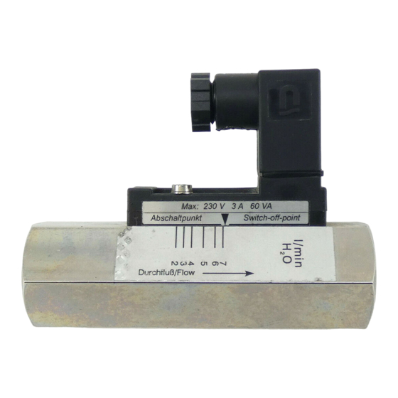
Fig. 1: SW-08 flow monitor Switch point adjustment scale Switch contact with female socket or sealed-in cable The flow monitor SW-08 monitors the continuous flow of liquids. It is designed for installation in pipe sys- tems. A float inside the device is moved by the medium flowing through it. -
Page 8: Safety
Safety Explanation of symbols Safety 2.1 Explanation of sym- This chapter provides an overview of important safety aspects required for bols optimum protection of personnel as Safety instructions well as for safe installation and safe operation of the device. Safety instructions in this manual are marked by symbols. - Page 9 Safety Explanation of symbols Designates step-by-step han- dling instructions CAUTION! ð Designates a state or an This combination of symbol and automatic sequence as a signal word indicates a possibly result of a specific operating dangerous situation that might step result in minor or slight injuries if it is not avoided.
-
Page 10: Correct Use In Accordance With These Instructions
There are no explosion-proof limit – Do not install the flow monitor switches available for the current as a load bearing part within a SW-08 (1/2“) series. pipeline system Any additional or different application, – The flow monitor must be... -
Page 11: Hazards From Electrical Current
DANGER! Danger to life from electrical DANGER! current! There is an immediate risk to life The SW-08 (1/2“) series may not from electrocution on touching live be employed in explosion hazard parts. Damaged electrical insula- zones. tion or components can be extremely dangerous. -
Page 12: Mechanical Hazards
Safety Special precautions > Mechanical hazards 2.3.2 Mechanical hazards – Never bridge fuses or put them out of operation. Always observe the correct current WARNING! ratings when replacing fuses – Keep moisture away from live Risk of injury due to fractured parts. -
Page 13: Hazards From High Or Low Temperatures
Safety Special precautions > Radiation hazards 2.3.3 Hazards from high 2.3.4 Radiation hazards or low temperatures Strong magnetic fields Hot or cold surfaces WARNING! WARNING! Danger to life from strong mag- netic fields! Risk of injury from hot or cold surfaces! Strong magnetic fields may cause severe injuries or even be fatal, as... -
Page 14: Hazards Caused By Media
Safety Personnel requirements 2.4 Personnel require- – Do not place any electronic ments storage media, credit cards, etc. within the vicinity of the magnetic source. Data could WARNING! be deleted Risk of injury due to use of insufficiently trained and quali- fied personnel! 2.3.5 Hazards caused by If unqualified personnel work on... -
Page 15: Personal Safety Equipment
Safety Personal safety equipment The following lists the personnel quali- When performing the various tasks at, fications for the various areas of and with the device, personnel must activity: wear personal safety equipment. Spe- cial reference is made of this in the Qualified electrician individual chapters within these Oper- Due to specialized training, knowledge... -
Page 16: Protective Systems
Safety Spare parts 2.6 Protective systems Protective gloves protect the hands from friction, burns, grazing, abrasion, Integration within an emergency- surface cuts or deeper injuries, as well stop concept is required as from direct contact with hot or cold surfaces. The device is designed for use as a part of a machine or system. -
Page 17: Environmental Protection
Safety Responsibility of the owner Always purchase spare parts from an Cleaning fluids authorized dealer or directly from the Solvent-based cleaning fluids contain manufacturer (For contact details, see toxic substances. They must never be Page 2). released into the environment and The spare parts list is in the annex. - Page 18 Safety Responsibility of the owner In addition to the safety instructions The owner must clearly regulate contained in these Operating Instruc- and determine responsibilities for tions, the safety, accident prevention installation, operation, trouble- and environmental protection regula- shooting, maintenance and tions applicable to the field of applica- cleaning.
- Page 19 Safety Responsibility of the owner The owner must ensure that the maintenance intervals described in these Operating Instructions are adhered to at all times. The owner must ensure that the device is completely free of any residual media before disposal. Remains of corrosive or toxic materials must be neutralized.
-
Page 20: Design And Function
Switchpoint adjustment scale Process connection (inlet) 3.2 Device description SW-08 flow monitors work according to the functional principle of the variable area flow meter. The flow monitor is installed into a pipe system and meas- ures the flow rate of the medium flowing through the pipe system. -
Page 21: Component Description
3.3 Component descrip- Switch point adjustment scale tion Switch contact Fig. 4: Switch point adjustment scale SW-08 A scale is applied to the device body, Fig. 3: Switch contact and female to which the desired switch point can socket be adjusted. -
Page 22: Transport, Packaging And Storage
Transport, packaging and storage Packaging Transport, packaging and storage 4.1 Safety instructions 4.2 Transport inspec- for transport tion On delivery, make an immediate check for completeness and check for trans- port damages. Improper transport If there are any visible external trans- port damages then proceed as follows: NOTICE! Do not accept the delivery... -
Page 23: Symbols On The Shipping Box
Transport, packaging and storage Storage Handling packaging materials Fragile Dispose of packaging material in accordance with the valid legal regula- tions and local ordinances. NOTICE! Designates packages with breakable Danger to the environment due or damageable contents. to incorrect disposal! Handle the package carefully and do Packaging is made of valuable raw not allow it to fall or be subjected to jar-... - Page 24 Transport, packaging and storage Storage Storage instructions in addition to the instructions listed here may be listed on the packages. Follow these instructions also. 20.02.2015...
-
Page 25: Installation And Initial Startup
Installation and initial startup Requirements at the place of installation Installation and initial startup 5.1 Safety Safeguard against restart Incorrect installation and initial startup WARNING! Danger to life due to unauthor- ized restart! WARNING! There is a risk of severe or even Risk of injury due to incorrect fatal injuries from unauthorized installation and initial startup! -
Page 26: Preparatory Work
Installation and initial startup Preparatory work The flow monitor must be installed in such a way as to preclude WARNING! damage by outside force. It must be ensured that the flow monitor Danger due to incorrect installa- cannot be damaged. If necessary, tion! install an appropriate impact pro- If the criteria listed above are not... - Page 27 Installation and initial startup Preparatory work Only install the flow monitor in one of Unimpeded flow sections the positions displayed in the drawing. The medium must flow in the direction of the arrow (from a low to a high scale NOTICE! value).
- Page 28 Installation and initial startup Preparatory work Unimpeded outlet Fig. 7: Unimpeded outlet Fig. 6: Unimpeded flow sections If the pipe system ends at an unim- peded outlet, the flow monitor must not 10x DN be installed directly in front of the 5x DN opening.
- Page 29 Installation and initial startup Preparatory work Strainer Prepare the device NOTICE! Risk of damage to property due to contamination! Contamination and deposits may impair the free movement of the float, thereby damaging the device. – Ensure that there are no for- eign particles in the device –...
-
Page 30: Installation In The Pipe System
Installation and initial startup Installation in the pipe system 5.4 Installation in the pipe system WARNING! Risk of injury from hot or cold surfaces! Pipelines can heat up/cool down dramatically due to the media WARNING! flowing through them. Skin contact Risk of injury from pressurized with hot or cold surfaces may pipes! - Page 31 Installation and initial startup Installation in the pipe system WARNING! A suitable sealant must be Risk of injury from media in the selected depending on the condi- pipe system! tion/composition of the pipe lines, If the pipe system contains haz- the medium and the operating and ardous media, severe injuries may environmental conditions.
- Page 32 Installation and initial startup Installation in the pipe system Sealing the pipe connections Personnel: Qualified personnel Nap the thread. Fig. 10: Pipe connection with sealing thread ð The pipe line is now ready for installation (Fig. 10) Fig. 9: Apply sealing thread Apply sealing thread (Fig.
- Page 33 Installation and initial startup Installation in the pipe system Install device in pipe system Personnel: Qualified personnel Protective equipment: Protective gloves Tool: Fixed spanner CAUTION! Fig. 12: Screw in the device Do not hold the device by its Keep turning in the adapter threads.
-
Page 34: Initial Startup
Installation and initial startup Initial startup 5.5 Initial startup NOTICE! The following steps must be carried out before initial startup and any subse- Vent the pipe line. If there quent startup (e.g. after removal and are air bubbles in the line installation during maintenance). -
Page 35: Electrical Connection
Installation and initial startup Electrical connection > Plug connector DIN 43650 5.6 Electrical connec- – Secure against switching tion back on – Check for absence of The electrical connection of the flow voltage monitor is accomplished through the connector plug or the cast on power –... -
Page 36: Plug Connector M12X1
Installation and initial startup Electrical connection > Plug connector M12x1 Fig. 14: Pin assignment, plug socket, Fig. 16: Pin assignment, plug socket, normally-open contact. The ground-pin change-over contact. The ground-pin is is not used. not used. change over: 5.6.2 Plug connector M12x1 Wiring diagram, connector M12x1 Fig. -
Page 37: Cable
Installation and initial startup Electrical connection > Cable Fig. 19: Switch position under no-flow condition 5.6.3 Cable The individual cores of the cable are numbered according to the following connection diagrams. Wiring diagram normally open: change over: Fig. 17: Pin assignment, connector M12x1 (Form 15x50) Wiring diagram Normally open:... -
Page 38: Degree Of Protection (Ip-Code)
Installation and initial startup Plug connection 5.6.4 Degree of protection Personnel: (IP-Code) Qualified electrician The specified degree of protection (IP) Tool: is only ensured if approved connection Flat-bladed screwdriver material is used (see following table). Device Specifi- Degree of connec- cation protection tion... - Page 39 Installation and initial startup Plug connection Fig. 23: Disconnect the screw connec- tion Disconnect the screw connec- tion (Fig. 23/01) by turning to the right Fig. 22: Disconnect inner section Guide the connection cable through the screw connection in Remove the inner section from the socket the socket by inserting a flat- bladed screwdriver into the slot...
- Page 40 Installation and initial startup Plug connection Retighten the screw connection Plug the socket onto the connec- (Fig. 23/01) by turning it to the tion plug and tighten the fixing right. screw (Fig. 20). Fig. 24: Pin assignment, plug socket, Normally Open Contact (Form 15x50) 20.02.2015...
-
Page 41: Contact Protection Measures
Installation and initial startup Contact protection measures Inductive load There is danger of voltage peaks from inductive loads when switching off (up to 10 times the rated voltage). Induc- tive loads are caused by, e.g.: Contactors, relays Solenoid valves Electric motors Examples of protective measures: Fig. - Page 42 Installation and initial startup Contact protection measures Protection against ohmic loads can be achieved through installation of a resistor in the circuit, or by heating the glow filament. For connection to high- impedance consumers (ex. PLC), a protective circuit is not needed. Fig.
-
Page 43: Operation
Operation Switch point adjustment Operation 6.1 Switch point adjust- Fig. 31: Loosen set screw ment Loosen the set screw of the switch contact (Fig. 31/1) using Setting the switch point of an a Hex screwdriver. installed device Slide the switch contact to the flow value to be monitored. - Page 44 Operation Switch point adjustment ð The set switch point corre- Setting the switch point of a non- sponds to the switch-off installed device point of the switch contact by decreasing flow. Fig. 32: Loosen the set screw Loosen the set screw of the switch contact (Fig.
-
Page 45: Checking The Flow
Operation Checking the flow 6.2 Checking the flow Read-off the switch value from the adjustment scale. Reading-off the switch value Personnel: Qualified personnel Protective equipment: Goggles Fig. 33: Reading-off the switch point value Make sure that the setting arrow and the scale mark of the switchpoint adjustment scale are in alignment (Fig. -
Page 46: Troubleshooting
Troubleshooting Safety Troubleshooting 7.1 Safety This chapter describes possible mal- functions of the device, their causes Work carried out incorrectly to and repair. remedy a malfunction If malfunctions persist or increase, shorten the maintenance interval to meet the actual operating conditions. WARNING! For malfunctions not described in this Risk of injury due to incorrect... - Page 47 Troubleshooting Safety Conduct in case of malfunction The complete machine or system may be unsafe if there is a defect at the flow monitor (e.g. fractured housing). The following always applies: In case of malfunctions that present an immediate danger to persons or valuables, proceed according to the valid emer- gency plans for the system...
-
Page 48: Troubleshooting Guide
Troubleshooting Troubleshooting guide 7.2 Troubleshooting guide Fault description Cause Remedy Personnel The switch contact No medium Check that medium is Qualified does not switch. flowing through flowing through the pipe- personnel flow monitor line Flow is too low or Adjust the switch Qualified the switch con- contact to a lower... - Page 49 Troubleshooting Troubleshooting guide Fault description Cause Remedy Personnel Float is stuck Disassemble and clean Qualified the device personnel Switch contact is Remedy the cause of Qualified defective the defect (short-cir- personnel cuit, overload) Replace the switch contact The switch point is Improper scale Request proper conver- Qualified...
-
Page 50: Maintenance
8.1 Safety 8.2 Maintenance plan Maintenance work performed incor- Intervals for replacing wear parts rectly SW-08 type flow monitors require very little maintenance due to the small number of moving parts. The intervals WARNING! for the replacement of wear parts... -
Page 51: Removal From The Pipe System
Maintenance Removal from the pipe system Interval Maintenance work Personnel Visual inspection for dirt/soiling Qualified personnel Visual inspection for free-movement of float Qualified personnel Visual inspection for leaks from the device Qualified personnel Check function of switch contact Qualified personnel 8.3 Removal from the pipe system WARNING! -
Page 52: Disassembly
Maintenance Disassembly Removing the device from the pipe system WARNING! Personnel: Risk of injury from media in the Qualified personnel pipe system! Protective equipment: If the pipe system contains haz- ardous media, severe injuries may With hazardous media, the protec- be caused by escaping media. - Page 53 Maintenance Disassembly Protective equipment: With hazardous media, the protec- WARNING! tive equipment specified in the Risk of injury due to incorrect Safety Data Sheet of the medium disassembly! must be worn. In addition, the specifications of the system oper- – The device may still contain ator must be followed.
- Page 54 Maintenance Disassembly Fig. 34: Loosen process connection Fig. 35: Remove the process connec- (outlet) tion (outlet) Loosen the process connection Unscrew the process connection (outlet) (Fig. 34) using the (outlet) from the device body proper sized fixed spanner (Fig. 35). If necessary, remove wrench.
- Page 55 Maintenance Disassembly Insert socket wrench into the threaded ring insertion tool and loosen the threaded ring (Fig. 37). Hold the device body in place using a proper sized spanner wrench. Fig. 36: Insert threaded ring insertion tool (outlet) Insert the threaded ring insertion tool into the device outlet (Fig.
- Page 56 Maintenance Disassembly The inner parts of the flow mon- itor consist of the spring (Fig. 40/1), magnets (Fig. 40/2) and float (Fig. 40/3). Fig. 39: Remove inner parts Carefully turn the device body 180° and remove the inner parts (float, magnets and spring) (Fig.
-
Page 57: Maintenance
Maintenance Maintenance > Cleaning 8.5.1 Cleaning It is the responsibility of the operator to establish appropriate intervals and pro- cedures for cleaning the individual parts of the device. It must be ensured that the parts are not damaged during the cleaning process. When using cleaning agents, it must be ensured that these are not aggressive to the parts and that there will be no dan-... -
Page 58: Parts Replacement
Maintenance Maintenance > Assembly Protective equipment: With hazardous media, the protec- CAUTION! tive equipment specified in the Risk of injury due to damaged Safety Data Sheet of the medium parts! must be worn. In addition, the specifications of the system oper- If parts of the device are broken or ator must be followed. - Page 59 Maintenance Maintenance > Assembly Carefully install the O-rings Personnel: (Fig. 43) with the aid of the O- Qualified personnel ring installation tool (Fig. 43) Tool: onto both process connections Flat-bladed screwdriver (inlet and outlet), so that they are properly seated in the O-ring Torque screwdriver and assorted grooves of the process connec- blades...
- Page 60 Maintenance Maintenance > Assembly Fig. 45: Insert process connection Fig. 46: Tighten process connection (inlet) (inlet) Insert the process connection Using a proper sized fixed (inlet) into the device body (inlet) spanner tighten the process con- (Fig. 45) nection (inlet). Hold the device body in place using a suitable fixed spanner (Fig.
- Page 61 Maintenance Maintenance > Assembly Fig. 47: Inner parts Fig. 48: Insert inner parts Insert spring (Fig. 47/1) with Insert float with magnets and magnets (Fig. 47/2) into the float spring into the device body (Fig. 47/3) ensuring proper mag- (Fig. 48) netic pole orientation (north pole toward device outlet) 20.02.2015...
- Page 62 Maintenance Maintenance > Assembly Lightly seat the threaded ring (outlet) with the aid of the threaded ring insertion tool and tighten with a torque wrench (Fig. 50), observing the proper torque ( Ä Chapter 11.1 “Tight- ening torque” on page 74) Fig.
- Page 63 Maintenance Maintenance > Assembly Fig. 52: Tighten process connection Fig. 53: Check for smooth operation (outlet) Check the float for ease of Using a proper sized fixed movement (Fig. 53) by applying spanner tighten the process con- light pressure with the test rod nection (outlet).
-
Page 64: Switch Contact Replacement
Maintenance Maintenance > Switch contact replacement 8.5.4 Switch contact replacement Tool: Flat-bladed screwdriver Hex screwdriver Fig. 56: Loosen set screw Using a Hex screwdriver (Fig. 56) remove the set screw of the switch contact Fig. 54: Loosen female socket Loosen the fixing screw of the female socket (Fig. -
Page 65: Measures To Be Taken After Maintenance Work
Maintenance Measures to be taken after maintenance work 8.6 Measures to be Connect a continuity meter. For Normally Open Contact (NOC), taken after mainte- connect pin 1 and pin 2. For nance work Change-Over Contact (COC), connect pin 1 and pin 3. Take the following steps after comple- tion of maintenance work and before Slide the switch contact in the... -
Page 66: Disassembly And Disposal
Disassembly and disposal Disassembly Disassembly and disposal 9.2 Disassembly After its period of useful life, the device must be disassembled and disposed of in an environmentally safe manner. Before starting disassembly: 9.1 Safety Remove operating materials and packaging and dispose of properly. WARNING! Risk of injury if disassembled Personnel:... -
Page 67: Return Materials
Profimess will apply. Return shipments which do not comply with the returns – Have electrical scrap, elec- policy may be refused by Profimess at tronic components, lubricants the expense of the consignor. and other supplies disposed of by approved specialists 9.4 Disposal... -
Page 68: Technical Data
Technical data Switch contact data plate Technical data 10.1 Device data plate The data plate is on the mechanical part of the flow monitor/flow meter and contains the following information: 1. Ordering number 2. Operating range 3. Process connection 4. Serial number 5. -
Page 69: Dimension Sheet
Technical data Dimension sheet 10.3 Dimension sheet 20.02.2015... -
Page 70: General Specifications
Technical data General specifications 10.4 General specifications Type Overall dimensions (mm) SW-08 118,6 SW-08 118,6 SW-08 118,6 Type Overall dimensions (mm) weight (g) ** SW-08 27,7 31,2 38,9 ca. 85 27,7 31,2 38,9 ca. 85 31,2 38,9 ca. 85 SW-08... -
Page 71: Electrical Specifications
Technical data Electrical specifications Type Overall dimensions (mm) weight (g) ** * NPT thread on request **Sealed-in cable weight 2m ca. 80g 10.5 Electrical specifications Change-Over Contact (COC) Data Value Unit Voltage 250 V Current, maximum 1,5 A Power, maximum 50 VA Minimum load 3 VA... -
Page 72: Measuring Ranges
60 VA Change-Over Contact (COC) PLC Data Value Unit Voltage 250 V Current, maximum Power, maximum 60 VA 10.6 Measuring ranges 10.6.1 Standard measuring ranges Type Switch range for oil, density 0,9 kg/dm l/min SW-08.X.X.1.03. 0,5 – 1,6 8–25,5 20.02.2015... -
Page 73: Operating Data
Measuring accuracy ± 10 % of full scale value Min. media temp. °C It must be ensured that the medium does not freeze. The devices in the SW-08 (1/2“) series are not suitable for use in explosion hazard zones. 20.02.2015... -
Page 74: Annex
Annex Replacement parts Annex 11.1 Tightening torque Component/ Description Size Torque Number function Threaded ring Threaded ring G1/2" 5 Nm (outlet) Connection fit- Process con- G1/2" 40 Nm ting nection (inlet/ outlet) Switch contact slotted cyl- M3x10 0,4 Nm locking screw inder head screw 11.2... - Page 75 Annex Replacement parts The following replacement parts drawing provides an example of the construction of a SW-08 type flow monitor. The actual configuration may vary depending on the model. Item No. of Description pieces Process connection (inlet) O-Ring (seal) Device body...
-
Page 76: Tools
Annex Sealant Item No. of Description pieces Threaded ring (outlet) Process connection (outlet) Cylinder pin (switch contact) Switch contact with male connector Female socket and gasket Fixing screw (female socket) Set screw (switch contact) 11.3 Tools 11.4 Sealant The following tools are required: Tools Fixed spanner 24, 27 mm Before using a sealant, ensure that... -
Page 77: Lubricants
Annex Lubricants 11.5 Lubricants Before using a lubricant, always make sure that it is compatible with the oper- ating medium. For the proper mounting of O-rings, an O-ring installation tool may be purchased from the manufacturer. The following lubricants are suitable to facilitate installing the O-rings: Lubricant O-ring material EPDM... - Page 78 Profimess GmbH Twischlehe 5 D-27580 Bremerhaven Operating instructions SW-08 (1/2“) Varible Area Flowmeter and Switch Status: February 2015 Technical modifications reserved...
- Page 79 Profimess GmbH Twischlehe 5 27570 Bremerhaven Germany Telephone: +49 471 98 24 - 151 Fax: +49 471 98 24 - 152 email: info@profimess.de Internet: www.profimess.com 23.02.2015...
- Page 80 – even in part – as well as dissemina- tion and/or communication of their con- tent is forbidden without prior written authorization from PROFIMESS Limitations of liability ("manufacturer"). Violations All details and instructions in this...
- Page 81 Table of contents Table of contents Overview...................... 7 1.1 Short description.................. 7 1.2 Warranty and guarantee provisions............. 7 1.3 Customer service................. 7 Safety......................8 2.1 Explanation of symbols................ 8 2.2 Correct use in accordance with these instructions......10 2.3 Special precautions................11 2.3.1 Hazards from electrical current............
- Page 82 Table of contents 5.2 Requirements at the place of installation........... 26 5.3 Preparatory work................27 5.4 Installation in the pipe system............32 5.5 Initial startup..................36 5.6 Electrical connection................37 5.6.1 Plug connector DIN 43650.............. 37 5.6.2 Plug connector M12x1..............38 5.6.3 Cable....................
- Page 83 Table of contents 9.4 Disposal..................... 71 Technical data................... 72 10.1 Device data plate................72 10.2 Switch contact data plate..............72 10.3 Dimension sheet................73 10.4 General specifications..............74 10.5 Electrical specifications..............75 10.6 Measuring ranges................76 10.6.1 Standard measuring ranges............76 10.7 Operating data.................
-
Page 84: Overview
Warranty and guarantee provisions are contained in the general terms and conditions of the manufacturer. 1.3 Customer service Fig. 1: SW-08 flow monitor For technical information, please con- Switch point adjustment scale tact our customer service department (concealed in this view) (for contact details, see Page 2). -
Page 85: Safety
Safety Explanation of symbols Safety 2.1 Explanation of sym- This chapter provides an overview of important safety aspects required for bols optimum protection of personnel as Safety instructions well as for safe installation and safe operation of the device. Safety instructions in this manual are marked by symbols. - Page 86 Safety Explanation of symbols Designates step-by-step han- dling instructions CAUTION! ð Designates a state or an This combination of symbol and automatic sequence as a signal word indicates a possibly result of a specific operating dangerous situation that might step result in minor or slight injuries if it is not avoided.
-
Page 87: Correct Use In Accordance With These Instructions
– Do not use the flow monitor There are no explosion-proof limit with media containing solids or switches available for the current abrasives SW-08 (1/2“) series. – Only use the flow monitor with media previously approved by the manufacturer –... -
Page 88: Special Precautions
Only qualified electricians shall work on the electrical system. DANGER! – If the insulation is damaged The SW-08 (1/2“) series may not then immediately switch off be employed in explosion hazard and have repairs carried out. zones. – Before commencing work on... -
Page 89: Mechanical Hazards
Safety Special precautions > Mechanical hazards 2.3.2 Mechanical hazards – Never bridge fuses or put them out of operation. Always observe the correct current WARNING! ratings when replacing fuses – Keep moisture away from live Risk of injury due to fractured parts. -
Page 90: Hazards From High Or Low Temperatures
Safety Special precautions > Radiation hazards 2.3.3 Hazards from high 2.3.4 Radiation hazards or low temperatures Strong magnetic fields Hot or cold surfaces WARNING! WARNING! Danger to life from strong mag- netic fields! Risk of injury from hot or cold surfaces! Strong magnetic fields may cause severe injuries or even be fatal, as... -
Page 91: Hazards Caused By Media
Safety Personnel requirements 2.4 Personnel require- – Do not place any electronic ments storage media, credit cards, etc. within the vicinity of the magnetic source. Data could WARNING! be deleted Risk of injury due to use of insufficiently trained and quali- fied personnel! 2.3.5 Hazards caused by If unqualified personnel work on... -
Page 92: Personal Safety Equipment
Safety Personal safety equipment The following lists the personnel quali- When performing the various tasks at, fications for the various areas of and with the device, personnel must activity: wear personal safety equipment. Spe- cial reference is made of this in the Qualified electrician individual chapters within these Oper- Due to specialized training, knowledge... -
Page 93: Protective Systems
Safety Spare parts 2.6 Protective systems Protective gloves protect the hands from friction, burns, grazing, abrasion, Integration within an emergency- surface cuts or deeper injuries, as well stop concept is required as from direct contact with hot or cold surfaces. The device is designed for use as a part of a machine or system. -
Page 94: Environmental Protection
Safety Responsibility of the owner Always purchase spare parts from an Cleaning fluids authorized dealer or directly from the Solvent-based cleaning fluids contain manufacturer (For contact details, see toxic substances. They must never be Page 2). released into the environment and The spare parts list is in the annex. - Page 95 Safety Responsibility of the owner In addition to the safety instructions The owner must clearly regulate contained in these Operating Instruc- and determine responsibilities for tions, the safety, accident prevention installation, operation, trouble- and environmental protection regula- shooting, maintenance and tions applicable to the field of applica- cleaning.
- Page 96 Safety Responsibility of the owner The owner must ensure that the maintenance intervals described in these Operating Instructions are adhered to at all times. The owner must ensure that the device is completely free of any residual media before disposal. Remains of corrosive or toxic materials must be neutralized.
-
Page 97: Design And Function
Device description Design and function 3.1 Overview 3.2 Device description SW-08 flow monitors work on the principle of the variable area flow meter. The flow monitor is installed into a pipe system and measures the flow rate of the medium flowing through the pipe system. -
Page 98: Component Description
Design and function Component description 3.3 Component descrip- Switchpoint adjustment scale tion Switch contact Fig. 4: Switchpoint adjustment scale A scale is applied to the device body, to which the desired switch point can Fig. 3: Switch contact and female be adjusted. - Page 99 Design and function Component description Indicator scale Fig. 5: Indicator scale On the device, a display housing is mounted with integral indicator scale and pointer. The pointer displays the current flow value. 23.02.2015...
-
Page 100: Transport, Packaging And Storage
Transport, packaging and storage Packaging Transport, packaging and storage 4.1 Safety instructions 4.2 Transport inspec- for transport tion On delivery, make an immediate check for completeness and check for trans- port damages. Improper transport If there are any visible external trans- port damages then proceed as follows: NOTICE! Do not accept the delivery... -
Page 101: Symbols On The Shipping Box
Transport, packaging and storage Storage Handling packaging materials Fragile Dispose of packaging material in accordance with the valid legal regula- tions and local ordinances. NOTICE! Designates packages with breakable Danger to the environment due or damageable contents. to incorrect disposal! Handle the package carefully and do Packaging is made of valuable raw not allow it to fall or be subjected to jar-... - Page 102 Transport, packaging and storage Storage Storage instructions in addition to the instructions listed here may be listed on the packages. Follow these instructions also. 23.02.2015...
-
Page 103: Installation And Initial Startup
Installation and initial startup Requirements at the place of installation Installation and initial startup 5.1 Safety Safeguard against restart Incorrect installation and initial startup WARNING! Danger to life due to unauthor- ized restart! WARNING! There is a risk of severe or even Risk of injury due to incorrect fatal injuries from unauthorized installation and initial startup! -
Page 104: Preparatory Work
Installation and initial startup Preparatory work The flow monitor must be installed in such a way as to preclude WARNING! damage by outside force. It must be ensured that the flow monitor Danger due to incorrect installa- cannot be damaged. If necessary, tion! install an appropriate impact pro- If the criteria listed above are not... - Page 105 Installation and initial startup Preparatory work Installation position/direction of flow Fig. 6: Installation position/direction of flow Only install the flow monitor in one of the positions displayed in the drawing. The medium must flow in the direction of the arrow (from a low to a high scale value). 23.02.2015...
- Page 106 Installation and initial startup Preparatory work Unimpeded flow sections NOTICE! Measuring inaccuracy due to incorrect installation! The measuring accuracy of the flow monitor is influenced by its position within the pipe system. Changes in cross-section, branch- offs or bends in the pipe system impair measuring accuracy.
- Page 107 Installation and initial startup Preparatory work Unimpeded outlet Fig. 8: Unimpeded outlet If the pipe system ends at an unimpeded outlet, the flow monitor must not be installed directly in front of the opening. The device must always be completely filled with medium to ensure measuring accuracy.
- Page 108 Installation and initial startup Preparatory work Strainer Prepare the device NOTICE! Risk of damage to property due to contamination! Contamination and deposits may impair the free movement of the float, thereby damaging the device. – Ensure that there are no for- eign particles in the device –...
-
Page 109: Installation In The Pipe System
Installation and initial startup Installation in the pipe system 5.4 Installation in the pipe system WARNING! Risk of injury from hot or cold surfaces! Pipelines can heat up/cool down dramatically due to the media WARNING! flowing through them Skin contact Risk of injury from pressurized with hot or cold surfaces may pipes! - Page 110 Installation and initial startup Installation in the pipe system WARNING! A suitable sealant must be Risk of injury from media in the selected depending on the condi- pipe system! tion/composition of the pipe lines, If the pipe system contains haz- the medium and the operating and ardous media, severe injuries may environmental conditions.
- Page 111 Installation and initial startup Installation in the pipe system Sealing the pipe connections Personnel: Qualified personnel Nap the thread. Fig. 11: Pipe connection with sealing thread ð The pipe line is now ready for installation (Fig. 11) Fig. 10: Apply sealing thread Apply sealing thread (Fig.
- Page 112 Installation and initial startup Installation in the pipe system Install device in pipe system Personnel: Qualified personnel Protective equipment: Protective gloves Tool: Fixed spanner CAUTION! Fig. 13: Screw in the device Do not hold the device by its Keep turning in the adapter threads.
-
Page 113: Initial Startup
Installation and initial startup Initial startup 5.5 Initial startup NOTICE! The following steps must be carried out before initial startup and any subse- Vent the pipe line. If there quent startup (e.g. after removal and are air bubbles in the line installation during maintenance). -
Page 114: Electrical Connection
Installation and initial startup Electrical connection > Plug connector DIN 43650 5.6 Electrical connec- – Secure against switching tion back on – Check for absence of The electrical connection of the flow voltage monitor is accomplished through the connector plug or the cast on power –... -
Page 115: Plug Connector M12X1
Installation and initial startup Electrical connection > Plug connector M12x1 Fig. 15: Pin assignment, plug socket, Fig. 17: Pin assignment, plug socket, normally-open contact. The ground-pin change-over contact. The ground-pin is is not used. not used. change over: 5.6.2 Plug connector M12x1 Wiring diagram, connector M12x1 Fig. -
Page 116: Cable
Installation and initial startup Electrical connection > Cable Fig. 20: Switch position under no-flow condition 5.6.3 Cable The individual cores of the cable are numbered according to the following connection diagrams. Wiring diagram normally open: change over: Fig. 18: Pin assignment, connector M12x1 (Form 15x50) Wiring diagram Normally open:... -
Page 117: Degree Of Protection (Ip-Code)
Installation and initial startup Plug connection 5.6.4 Degree of protection Personnel: (IP-Code) Qualified electrician The specified degree of protection (IP) Tool: is only ensured if approved connection Flat-bladed screwdriver material is used (see following table). Device Specifi- Degree of connec- cation protection tion... - Page 118 Installation and initial startup Plug connection Fig. 23: Disconnect inner section Fig. 24: Remove the screw connection Remove the inner section from Remove the screw connection the socket by inserting a flat- (Fig. 24/1) by turning to the left. bladed screwdriver into the slot Guide the connection cable (Fig.
-
Page 119: Contact Protection Measures
Installation and initial startup Contact protection measures Place the socket onto the con- nection plug and tighten the fixing screw (Fig. 21) Fig. 26: Pin assignment, plug socket, Change-over contact (Form 15x50) 5.9 Contact protection Fig. 25: Pin assignment, plug socket, measures Normally Open Contact (Form 15x50) The Reed-switches used in the switch... - Page 120 Installation and initial startup Contact protection measures Inductive load There is danger of voltage peaks from inductive loads when switching off (up to 10 times the rated voltage). Induc- tive loads are caused by, e.g.: Contactors, relays Fig. 29: Protective measure against capacitive loads Solenoid valves Electric motors...
- Page 121 Installation and initial startup Contact protection measures Protection against ohmic loads can be achieved through installation of a resistor in the circuit, or by heating the glow filament. For connection to high- impedance consumers (ex. PLC), a protective circuit is not needed. 23.02.2015...
-
Page 122: Operation
Operation Operation 23.02.2015... -
Page 123: Toubleshooting
Toubleshooting Safety Toubleshooting 7.1 Safety This chapter describes possible mal- functions of the device, their causes Work carried out incorrectly to and repair. remedy a malfunction If malfunctions persist or increase, shorten the maintenance interval to meet the actual operating conditions. WARNING! For malfunctions not described in this Risk of injury due to incorrect... - Page 124 Toubleshooting Safety Conduct in case of malfunction The complete machine or system may be unsafe if there is a defect at the flow monitor (e.g. fractured housing). The following always applies: In case of malfunctions that present an immediate danger to persons or valuables, proceed according to the valid emer- gency plans for the system...
-
Page 125: Troubleshooting Guide
Toubleshooting Troubleshooting guide 7.2 Troubleshooting guide Fault description Cause Remedy Personnel The switch contact No medium Check that medium is Qualified does not switch. flowing through flowing through the pipe- personnel flow monitor line Flow is too low or Adjust the switch Qualified the switch con- contact to a lower... - Page 126 Toubleshooting Troubleshooting guide Fault description Cause Remedy Personnel Float is stuck Disassemble and clean Qualified the device personnel Switch contact is Remedy the cause of Qualified defective the defect (short-cir- personnel cuit, overload) Replace the switch contact The switch point is Improper scale Request proper conver- Qualified...
-
Page 127: Maintenance
8.1 Safety 8.2 Maintenance plan Maintenance work performed incor- Intervals for replacing wear parts rectly SW-08 type flow monitors require very little maintenance due to the small number of moving parts. The intervals WARNING! for the replacement of wear parts... -
Page 128: Removal From The Pipe System
Maintenance Removal from the pipe system Interval Maintenance work Personnel Visual inspection for dirt/soiling Qualified personnel Visual inspection for free-movement of float and Qualified personnel display pointer mechanism Visual inspection for leaks from the device Qualified personnel Check function of switch contact Qualified personnel 8.3 Removal from the pipe system... -
Page 129: Disassembly
Maintenance Disassembly Removing the device from the pipe system WARNING! Personnel: Risk of injury from media in the Qualified personnel pipe system! Protective equipment: If the pipe system contains haz- ardous media, severe injuries may With hazardous media, the protec- be caused by escaping media. - Page 130 Maintenance Disassembly Protective equipment: With hazardous media, the protec- WARNING! tive equipment specified in the Risk of injury due to incorrect Safety Data Sheet of the medium disassembly! must be worn. In addition, the specifications of the system oper- – The device may still contain ator must be followed.
- Page 131 Maintenance Disassembly Remove fixing screws from the Fig. 34 display housing cover (Fig. 32) Press out the display cover plate from the plastic housing (Fig. 34) Fig. 33 Carefully remove the display Fig. 35 housing cover plate and plastic Pull the scale support (with housing from the display base affixed scale) from the guides in plate by lifting straight up.
- Page 132 Maintenance Disassembly Fig. 37: Loosen process connection Fig. 38: Remove the process connec- (outlet) tion (outlet) Loosen the process connection Unscrew the process connection (outlet) (Fig. 37) using the (outlet) from the device body proper sized fixed spanner (Fig. 38). If necessary, remove wrench.
- Page 133 Maintenance Disassembly Fig. 39: Insert threaded ring insertion Fig. 40: Loosen threaded ring (outlet) tool (outlet) Insert socket wrench into the Insert the threaded ring insertion threaded ring insertion tool and tool into the device outlet loosen the threaded ring (Fig.
- Page 134 Maintenance Disassembly Fig. 41: Remove threaded ring (outlet) Fig. 43: Spring, magnets and float Unscrew the threaded ring The inner parts of the flow mon- (outlet) from the device body itor consist of the spring Fig. 41) (Fig. 43/3), magnets (Fig.
-
Page 135: Maintenance
Maintenance Maintenance Fig. 44: Loosen process connection Fig. 45: Remove process connection (inlet) (inlet) Loosen the process connection Unscrew the process connection (inlet) (Fig. 44) using the proper (inlet) from the device body sized fixed spanner wrench. (Fig. 45). If necessary, remove Hold the device body in place the O-ring from the process con- using a proper sized spanner... -
Page 136: Cleaning
Maintenance Maintenance > Cleaning 8.5.1 Cleaning CAUTION! It is the responsibility of the operator to establish appropriate intervals and pro- Risk of injury due to damaged cedures for cleaning the individual parts! parts of the device. It must be ensured If parts of the device are broken or that the parts are not damaged during damaged, they may cause injury... -
Page 137: Parts Replacement
Maintenance Maintenance > Assembly Protective equipment: Personnel: With hazardous media, the protec- Qualified personnel tive equipment specified in the Tool: Safety Data Sheet of the medium Flat-bladed screwdriver must be worn. In addition, the specifications of the system oper- Torque screwdriver and assorted ator must be followed. - Page 138 Maintenance Maintenance > Assembly Carefully install the O-rings (Fig. 46/2) with the aid of the O- ring installation tool (Fig. 46) onto both process connections (inlet and outlet), so that they are properly seated in the O-ring grooves of the process connec- tion (Fig.
- Page 139 Maintenance Maintenance > Assembly Fig. 49: Tighten process connection Fig. 50: Inner parts (inlet) Insert spring (Fig. 50/3) with Using a proper sized fixed magnets (Fig. 50/2) into the float spanner, tighten the process (Fig. 50/1) ensuring proper mag- connection (inlet). Hold the netic pole orientation (north pole device body in place using a toward device outlet).
- Page 140 Maintenance Maintenance > Assembly Fig. 51: Insert inner parts Fig. 52: Insert threaded ring (outlet) Insert float with magnets and Insert the threaded ring (outlet) spring into the device body into the device body (outlet) (Fig. 51). (Fig. 52). 23.02.2015...
- Page 141 Maintenance Maintenance > Assembly Fig. 53: Seat threaded ring (outlet) Fig. 54: Insert process connection (outlet) Lightly seat the threaded ring (outlet) with the aid of the Insert the process connection threaded ring insertion tool and (outlet) into the device body tighten with a torque wrench (outlet) (Fig.
- Page 142 Maintenance Maintenance > Assembly Fig. 56: Check for smooth operation Check the float for ease of movement (Fig. 56) by applying light pressure with the test rod. ð If the float moves sluggishly, then disassemble the device Ä Chapter 9.2 “Disas- sembly”...
- Page 143 Maintenance Maintenance > Assembly countersunk head screw is used Loosen, then remove the female for the long groove (pointer end) socket and connect a continuity and the cylinder head screws meter or other suitable test are used to secure the base instrument to the pins of the plate middle.
- Page 144 Maintenance Maintenance > Assembly positioning aid label and the label on the device body must be removed and repositioned. Parallax errors are to be avoided. Loosen the switch contact set screws and adjust the switch contact to a graduation mark in the middle of the scale on the device body.
-
Page 145: Switch Contact Replacement
Maintenance Maintenance > Switch contact replacement 8.5.4 Switch contact replacement Tool: Flat-bladed screwdriver Hex screwdriver Fig. 64: Loosen set screw Using a Hex screwdriver, (Fig. 64) loosen the set screw so that the switch contact can be removed. Fig. 62: Loosen female socket Loosen the fixing screw of the female socket (Fig. -
Page 146: Measures To Be Taken After Maintenance Work
Maintenance Measures to be taken after maintenance work 8.6 Measures to be Connect a continuity meter. For Normally Open Contact (NOC), taken after mainte- connect PIN 1 and PIN 2. For nance work Change-Over Contact (COC), connect PIN 1 and PIN 3. Take the following steps after comple- tion of maintenance work and before Slide the switch contact in the... -
Page 147: Disassembly And Disposal
Disassembly and disposal Disassembly Disassembly and disposal 9.2 Disassembly After its period of useful life, the device must be disassembled and disposed of in an environmentally safe manner. Before starting disassembly: 9.1 Safety Remove operating materials and packaging and dispose of properly. WARNING! Risk of injury if disassembled Personnel:... -
Page 148: Return Materials
Profimess will apply. Return shipments which do not comply with the returns – Have electrical scrap, elec- policy may be refused by Profimess at tronic components, lubricants the expense of the consignor. and other supplies disposed of by approved specialists 9.4 Disposal... -
Page 149: Technical Data
Technical data Switch contact data plate Technical data 10.1 Device data plate The data plate is on the mechanical part of the flow monitor/flow meter and contains the following information: 1. Ordering number 2. Operating range 3. Process connection 4. Serial number 5. -
Page 150: Dimension Sheet
Technical data Dimension sheet 10.3 Dimension sheet 23.02.2015... -
Page 151: General Specifications
Technical data General specifications 10.4 General specifications Type Overall dimensions (mm) SW-08 12,5 SW-08 SW-08 Type Overall dimensions (mm) weight (g) ** SW-08 27,5 ca. 70 ca. 70 27,5 ca. 70 SW-08 ca. 70 SW-08 ca. 70 * NPT thread on request ** Sealed-in cable weight, 2m ca. -
Page 152: Electrical Specifications
Technical data Electrical specifications 10.5 Electrical specifications Change-Over Contact (COC) Data Value Unit Voltage 250 V Current, maximum 1,5 A Power, Maximum 50 VA Minimum load 3 VA Normally Open Contact (NOC) Data Value Unit Voltage 230 V Current, maximum Power, maximum 60 VA Change-Over Contact (COC) M12x1 (-20 °C–85 °C) -
Page 153: Measuring Ranges
Power, maximum 60 VA 10.6 Measuring ranges 10.6.1 Standard measuring ranges Type Switch range for oil, density 0,9 kg/dm l/min SW-08.X.X.1.03. 0,5 – 1,6 8–25,5 SW-08.X.X.1.04. 0,8–3 13–48 SW-08.X.X.1.05. 2–7 32–111 * The specified data are switch-off points (other switch ranges are available on request). - Page 154 °C Measuring accuracy ± 10 % of full scale value Min. media temp. It must °C be ensured that the medium does not freeze. The devices in the SW-08 series are not suitable for use in explosion hazard zones. 23.02.2015...
-
Page 155: Annex
Annex Replacement parts Annex 11.1 Tightening torque Component/ Descriptiong Size Torque Number function Threaded ring Threaded ring G1/2" 5 Nm (outlet) Connection fit- Process con- G1/2" 40 Nm ting nection (inlet/ outlet) Display base countersunk M2x4 0,4 Nm plate (slot screw end) Display base... - Page 156 Annex Replacement parts The following replacement parts drawing provides an example of the construction of a SW-08 type flow monitor. The actual configuration may vary depending on the model. No. of Description pieces Process connection (inlet) O-ring (seal) Device body...
-
Page 157: Tools
Annex Sealant No. of Description pieces Cylinder pin (switch contact) Switch contact with male connector Female socket and gasket Fixing screw (female socket) Display, mechanical Set screw (switch contact) 11.3 Tools 11.4 Sealant The following tools are required: Tools Fixed spanner 24, 30 mm Before using a sealant, ensure that it is compatible with the media Flat-bladed screwdriver, width of... -
Page 158: Lubricants
Annex Lubricants 11.5 Lubricants Before using a lubricant, always make sure that it is compatible with the oper- ating medium. For the proper mounting of O-rings, an O-ring installation tool may be purchased from the manufacturer. The following lubricants are suitable to facilitate installing the O-rings: Lubricant O-ring material EPDM... - Page 159 Profimess GmbH Twischlehe 5 D-27580 Bremerhaven Operating instructions SW-08 (1“) Varible Area Flowswitch Status: February 2015 Technical modifications reserved...
- Page 160 Profimess GmbH Twischlehe 5 27570 Bremerhaven Germany Telephone: +49 471 98 24 - 151 Fax: +49 471 98 24 - 152 email: info@profimess.de Internet: www.profimess.com 20.02.2015...
- Page 161 – even in part – as well as dissemina- tion and/or communication of their con- tent is forbidden without prior written authorization from PROFIMESS Limitations of liability ("manufacturer"). Violations All details and instructions in this...
- Page 162 Table of contents Table of contents Overview...................... 7 1.1 Short description.................. 7 1.2 Warranty and guarantee provisions............. 7 1.3 Customer service................. 7 Safety......................8 2.1 Explanation of symbols................ 8 2.2 Correct use in accordance with these instructions......10 2.3 Special precautions................11 2.3.1 Hazards from electrical current............
- Page 163 Table of contents 5.2 Requirements at the place of installation........... 25 5.3 Preparatory work................26 5.4 Installation in the pipe system............30 5.5 Initial startup..................34 5.6 Electrical connection................35 5.6.1 Connector DIN 43650..............36 5.6.2 Plug connector M12x1..............37 5.6.3 Cable....................
- Page 164 Table of contents 9.3 Return Materials................. 70 9.3.1 Return Materials Authorization............70 9.4 Disposal..................... 70 Technical data................... 71 10.1 Device data plate................71 10.2 Switch contact data plate..............71 10.3 Dimension sheet................72 10.4 General specifications..............73 10.5 Electrical specifications..............76 10.6 Measuring ranges................
-
Page 165: Overview
Fig. 1: SW-08 flow monitor 01 Switch point adjustment scale 02 Switch contact with female socket or sealed-in cable The flow monitor SW-08 monitors the continuous flow of liquids. It is designed for installation in pipe sys- tems. A float inside the device is moved by the medium flowing through it. -
Page 166: Safety
Safety Explanation of symbols Safety 2.1 Explanation of sym- This chapter provides an overview of important safety aspects required for bols optimum protection of personnel as Safety instructions well as for safe installation and safe operation of the device. Safety instructions in this manual are marked by symbols. - Page 167 Safety Explanation of symbols Designates step-by-step han- dling instructions CAUTION! ð Designates a state or an This combination of symbol and automatic sequence as a signal word indicates a possibly result of a specific operating dangerous situation that might step result in minor or slight injuries if it is not avoided.
-
Page 168: Correct Use In Accordance With These Instructions
The intended use in explosion-hazard – Only use the flow monitor with zones is described in the Operating media previously approved by Instructions for "SW-08 (1“) Module the manufacturer ATEX" . – Do not use the flow monitor as the sole monitoring device to... -
Page 169: Special Precautions
Operating Instructions for "SW-08 (1“) Module ATEX" – Before commencing work on including all hazard statements live parts of the electrical sys- and warnings, therein. -
Page 170: Mechanical Hazards
Safety Special precautions > Mechanical hazards 2.3.2 Mechanical hazards – Never bridge fuses or put them out of operation. Always observe the correct current WARNING! ratings when replacing fuses – Keep moisture away from live Risk of injury due to fractured parts. -
Page 171: Hazards From High Or Low Temperatures
Safety Special precautions > Radiation hazards 2.3.3 Hazards from high 2.3.4 Radiation hazards or low temperatures Strong magnetic fields Hot or cold surfaces WARNING! WARNING! Danger to life from strong mag- netic fields! Risk of injury from hot or cold surfaces! Strong magnetic fields may cause severe injuries or even be fatal, as... -
Page 172: Hazards Caused By Media
Safety Personnel requirements 2.4 Personnel require- – Do not place any electronic ments storage media, credit cards, etc. within the vicinity of the magnetic source. Data could WARNING! be deleted Risk of injury due to use of insufficiently trained and quali- fied personnel! 2.3.5 Hazards caused by If unqualified personnel work on... -
Page 173: Personal Safety Equipment
Safety Personal safety equipment The following lists the personnel quali- When performing the various tasks at, fications for the various areas of and with the device, personnel must activity: wear personal safety equipment. Spe- cial reference is made of this in the Qualified electrician individual chapters within these Oper- Due to specialized training, knowledge... -
Page 174: Protective Systems
Safety Spare parts 2.6 Protective systems Protective gloves protect the hands from friction, burns, grazing, abrasion, Integration within an emergency- surface cuts or deeper injuries, as well stop concept is required as from direct contact with hot or cold surfaces. The device is designed for use as a part of a machine or system. -
Page 175: Environmental Protection
Safety Responsibility of the owner Always purchase spare parts from an Cleaning fluids authorized dealer or directly from the Solvent-based cleaning fluids contain manufacturer (For contact details, see toxic substances. They must never be Page 2). released into the environment and The spare parts list is in the annex. - Page 176 Safety Responsibility of the owner In addition to the safety instructions The owner must clearly regulate contained in these Operating Instruc- and determine responsibilities for tions, the safety, accident prevention installation, operation, trouble- and environmental protection regula- shooting, maintenance and tions applicable to the field of applica- cleaning.
- Page 177 Safety Responsibility of the owner The owner must ensure that the maintenance intervals described in these Operating Instructions are adhered to at all times. The owner must ensure that the device is completely free of any residual media before disposal. Remains of corrosive or toxic materials must be neutralized.
-
Page 178: Design And Function
04 Switchpoint adjustment scale 05 Process connection (inlet) 3.2 Device description SW-08 flow monitors work according to the functional principle of the variable area flow meter. The flow monitor is installed into a pipe system and meas- ures the flow rate of the medium flowing through the pipe system. -
Page 179: Component Description
3.3 Component descrip- Switch point adjustment scale tion Switch contact Fig. 4: Switch point adjustment scale SW-08 A measuring scale is applied to the Fig. 3: Switch contact and female device body, to which the desired socket switch point can be adjusted. -
Page 180: Transport, Packaging And Storage
Transport, packaging and storage Packaging Transport, packaging and storage 4.1 Safety instructions 4.2 Transport inspec- for transport tion On delivery, make an immediate check for completeness and check for trans- port damages. Improper transport If there are any visible external trans- port damages then proceed as follows: NOTICE! Do not accept the delivery... -
Page 181: Symbols On The Shipping Box
Transport, packaging and storage Storage Handling packaging materials Fragile Dispose of packaging material in accordance with the valid legal regula- tions and local ordinances. NOTICE! Designates packages with breakable Danger to the environment due or damageable contents. to incorrect disposal! Handle the package carefully and do Packaging is made of valuable raw not allow it to fall or be subjected to jar-... - Page 182 Transport, packaging and storage Storage Storage instructions in addition to the instructions listed here may be listed on the packages. Follow these instructions also. 20.02.2015...
-
Page 183: Installation And Initial Startup And Operation
Installation and initial startup and Operation Requirements at the place of installation Installation and initial startup and Operation 5.1 Safety Safeguard against restart Incorrect installation and initial startup WARNING! Danger to life due to unauthor- ized restart! WARNING! There is a risk of severe or even Risk of injury due to incorrect fatal injuries from unauthorized installation and initial startup! -
Page 184: Preparatory Work
Installation and initial startup and Operation Preparatory work The flow monitor must be installed in such a way as to preclude WARNING! damage by outside force. It must be ensured that the flow monitor Danger due to incorrect installa- cannot be damaged. If necessary, tion! install an appropriate impact pro- If the criteria listed above are not... - Page 185 Installation and initial startup and Operation Preparatory work Only install the flow monitor in one of Unimpeded flow sections the positions displayed in the drawing. The medium must flow in the direction of the arrow (from a low to a high scale NOTICE! value).
- Page 186 Installation and initial startup and Operation Preparatory work Unimpeded outlet Fig. 7: Unimpeded outlet If the pipe system ends at an unim- peded outlet, the flow monitor must not be installed directly in front of the opening. The device must always be completely filled with media to ensure measuring accuracy.
- Page 187 Installation and initial startup and Operation Preparatory work Strainer Prepare the device NOTICE! Risk of damage to property due to contamination! Contamination and deposits may impair the free movement of the float, thereby damaging the device. – Ensure that there are no for- eign particles in the device –...
-
Page 188: Installation In The Pipe System
Installation and initial startup and Operation Installation in the pipe system 5.4 Installation in the pipe system WARNING! Risk of injury from hot or cold surfaces! Pipelines can heat up/cool down dramatically due to the media WARNING! flowing through them. Skin contact Risk of injury from pressurized with hot or cold surfaces may pipes! - Page 189 Installation and initial startup and Operation Installation in the pipe system WARNING! A suitable sealant must be Risk of injury from media in the selected depending on the condi- pipe system! tion/composition of the pipe lines, If the pipe system contains haz- the medium and the operating and ardous media, severe injuries may environmental conditions.
- Page 190 Installation and initial startup and Operation Installation in the pipe system Sealing the pipe connections Personnel: Qualified personnel Nap the thread. Fig. 10: Pipe connection with sealing thread ð The pipe line is now ready for installation (Fig. 10) Fig. 9: Apply sealing thread Apply sealing thread (Fig.
- Page 191 Installation and initial startup and Operation Installation in the pipe system Install device in pipe system Personnel: Qualified personnel Protective equipment: Protective gloves Tool: Fixed spanner CAUTION! Fig. 12: Screw in the device Do not hold the device by the Keep turning in the adapter threads.
-
Page 192: Initial Startup
Installation and initial startup and Operation Initial startup 5.5 Initial startup NOTICE! The following steps must be carried out before initial startup and any subse- Vent the pipe line. If there quent startup (e.g. after removal and are air bubbles in the line installation during maintenance). -
Page 193: Electrical Connection
Installation and initial startup and Operation Electrical connection 5.6 Electrical connec- – Secure against switching tion back on – Check for absence of The electrical connection of the flow voltage monitor is accomplished through the connector plug or the cast on power –... -
Page 194: Connector Din 43650
Installation and initial startup and Operation Electrical connection > Connector DIN 43650 5.6.1 Connector DIN 43650 Wiring diagram of the supplied socket (DIN 43650, Form A) (Front view). Wiring diagram Fig. 15: Switch position under no-flow normally open: condition Fig. 13: Switch position under no-flow condition Fig. -
Page 195: Plug Connector M12X1
Installation and initial startup and Operation Electrical connection > Cable 5.6.2 Plug connector M12x1 Wiring diagram, socket (M12x1) Fig. 19: Switch position under no-flow condition 5.6.3 Cable The individual cores of the cable are numbered according to the following connection diagrams. Wiring diagram normally open: change over:... -
Page 196: Degree Of Protection (Ip-Code)
Installation and initial startup and Operation Plug connection 5.6.4 Degree of protection Personnel: (IP-Code) Qualified electrician The specified degree of protection (IP) Tool: is only ensured if approved connection Flat-bladed screwdriver material is used (see following table). Device Specifi- Degree of connec- cation protection... - Page 197 Installation and initial startup and Operation Plug connection Fig. 22: Disconnect inner section Remove the inner section from Fig. 23: Disconnect the screw connec- the socket by inserting a flat- tion bladed screwdriver into the slot (Fig. 22/1) and carefully pry out Disconnect the screw connec- the inner section.
-
Page 198: Contact Protection Measures
Installation and initial startup and Operation Contact protection measures Plug the socket onto the connec- tion plug and tighten the fixing screw (Fig. 20/1). Fig. 25: Pin assignment, plug socket, Change-over contact (Form 30x70) 5.9 Contact protection Fig. 24: Pin assignment, plug socket, measures Normally Open Contact (Form 30x70) The Reed-switches used in the switch... - Page 199 Installation and initial startup and Operation Contact protection measures Inductive load There is danger of voltage peaks from inductive loads when switching off (up to 10 times the rated voltage). Induc- tive loads are caused by, e.g.: Contactors, relays Fig. 28: Protective measure against capacitive loads Solenoid valves Electric motors...
- Page 200 Installation and initial startup and Operation Contact protection measures Protection against ohmic loads can be achieved through installation of a resistor in the circuit, or by heating the glow filament. For connection to high- impedance consumers (ex. PLC), a protective circuit is not needed. 20.02.2015...
-
Page 201: Operation
Operation Switch point adjustment Operation 6.1 Switch point adjust- Fig. 31: Loosen set screws ment Loosen the set screws of the switch contact (Fig. 31/1) using Setting the switch point of an a flat-bladed screwdriver. installed device Set the switch contact to the flow value to be monitored. - Page 202 Operation Switch point adjustment ð The set switch point corre- Setting the switch point of a non- sponds to the switch-off installed device point of the switch contact by decreasing flow. Fig. 32: Loosen the set screws Loosen the set screws of the switch contact (Fig.
-
Page 203: Checking The Flow
Operation Checking the flow 6.2 Checking the flow Read-off the switch value from the switch point adjustment Reading-off the switch value scale Personnel: Qualified personnel Protective equipment: Goggles Fig. 33: Reading-off the switch point (sample scale) Make sure that the setting arrow, the scale mark on the additional label on the guide rail and the scale mark of the switchpoint... -
Page 204: Troubleshooting
Troubleshooting Safety Troubleshooting 7.1 Safety This chapter describes possible mal- functions of the device, their causes Work carried out incorrectly to and repair. remedy a malfunction If malfunctions persist or increase, shorten the maintenance interval to meet the actual operating conditions. WARNING! For malfunctions not described in this Risk of injury due to incorrect... - Page 205 Troubleshooting Safety Conduct in case of malfunction The complete machine or system may be unsafe if there is a defect at the flow monitor (e.g. fractured housing). The following always applies: In case of malfunctions that present an immediate danger to persons or valuables, proceed according to the valid emer- gency plans for the system...
-
Page 206: Troubleshooting Guide
Troubleshooting Troubleshooting guide 7.2 Troubleshooting guide Fault description Cause Remedy Personnel The switch contact No medium Check that medium is Qualified does not switch. flowing through flowing through the pipe- personnel flow monitor line Flow is too low or Adjust the switch Qualified the switch con- contact to a lower... - Page 207 Troubleshooting Troubleshooting guide Fault description Cause Remedy Personnel Float is stuck Disassemble and clean Qualified the device personnel Switch contact is Remedy the cause of Qualified defective the defect (short-cir- personnel cuit, overload) Replace the switch contact The switch point is Improper scale Request proper conver- Qualified...
-
Page 208: Maintenance
8.1 Safety 8.2 Maintenance plan Maintenance work performed incor- Intervals for replacing wear parts rectly SW-08 type flow monitors require very little maintenance due to the small number of moving parts. The intervals WARNING! for the replacement of wear parts... -
Page 209: Removal From The Pipe System
Maintenance Removal from the pipe system Interval Maintenance work Personnel Visual inspection for dirt/soiling Qualified personnel Visual inspection for free-movement of float Qualified personnel Visual inspection for leaks from the device Qualified personnel Check function of switch contact Qualified personnel 8.3 Removal from the pipe system WARNING! -
Page 210: Disassembly
Maintenance Disassembly Removing the device from the pipe system WARNING! Personnel: Risk of injury from media in the Qualified personnel pipe system! Protective equipment: If the pipe system contains haz- ardous media, severe injuries may With hazardous media, the protec- be caused by escaping media. - Page 211 Maintenance Disassembly Protective equipment: With hazardous media, the protec- WARNING! tive equipment specified in the Risk of injury due to incorrect Safety Data Sheet of the medium disassembly! must be worn. In addition, the specifications of the system oper- – The device may still contain ator must be followed.
- Page 212 Maintenance Disassembly Fig. 34: Loosen process connection Fig. 35: Remove the process connec- (outlet) tion (outlet) Loosen the process connection Unscrew the process connection (outlet) (Fig. 34) using the (outlet) from the device body proper sized fixed spanner (Fig. 35). If necessary, remove wrench.
- Page 213 Maintenance Disassembly Insert socket wrench into the threaded ring insertion tool and loosen the threaded ring (Fig. 37). Hold the device body in place using a proper sized spanner wrench. Fig. 36: Insert threaded ring insertion tool (outlet) Insert the threaded ring insertion tool into the device outlet (Fig.
- Page 214 Maintenance Disassembly The inner parts of the flow mon- itor consist of the (Fig. 40/01) spring, (Fig. 40/02) magnets and (Fig. 40/03) float. Fig. 39: Remove inner parts Carefully turn the device body 180° and remove the inner parts (float, magnets and spring) (Fig.
- Page 215 Maintenance Disassembly Fig. 42: Remove the process connec- Fig. 43: Insert threaded ring insertion tion (inlet) tool (inlet) Unscrew the process connection Insert the threaded ring insertion (inlet) from the device body tool into the device inlet (Fig. 43) (Fig. 42). If necessary, remove and turn until it rest in the the O-ring from the process con- keyway of the threaded ring...
-
Page 216: Maintenance
Maintenance Maintenance > Cleaning 8.5.1 Cleaning Insert socket wrench into the threaded ring insertion tool and It is the responsibility of the operator to loosen the threaded ring establish appropriate intervals and pro- (Fig. 37). Hold the device body cedures for cleaning the individual in place using a proper sized parts of the device. -
Page 217: Parts Replacement
Maintenance Maintenance > Assembly Protective equipment: With hazardous media, the protec- CAUTION! tive equipment specified in the Risk of injury due to damaged Safety Data Sheet of the medium parts! must be worn. In addition, the specifications of the system oper- If parts of the device are broken or ator must be followed. - Page 218 Maintenance Maintenance > Assembly Carefully install the O-rings Personnel: (Fig. 46/02) with the aid of the Qualified personnel O-ring installation tool Tool: (Fig. 46/01) onto both process Flat-bladed screwdriver connections (inlet and outlet), so that they are properly seated in Torque screwdriver and assorted the O-ring grooves of the blades...
- Page 219 Maintenance Maintenance > Assembly Fig. 48: Insert threaded ring (inlet) Insert the threaded ring (inlet) into the device body (Fig. 48) Fig. 50: Insert process connection (inlet) Insert the process connection (inlet) into the device body (inlet) (Fig. 50) Fig. 49: Seat threaded ring (inlet) Lightly seat the threaded ring (inlet) with the aid of the threaded ring insertion tool.
- Page 220 Maintenance Maintenance > Assembly Fig. 51: Tighten process connection Fig. 52: Inner parts (inlet) Insert spring (Fig. 52/01) with Using a proper sized fixed magnets (Fig. 52/02) into the spanner tighten the process con- float (Fig. 52/03) ensuring proper nection (inlet). Hold the device magnetic pole orientation (north body in place using a suitable pole toward device outlet)
- Page 221 Maintenance Maintenance > Assembly Fig. 53: Insert inner parts Fig. 54: Insert threaded ring (outlet) Insert float with magnets and Insert the threaded ring (outlet) spring into the device body into the device body (outlet) (Fig. 53) (Fig. 54) Fig. 55: Seat threaded ring (outlet) 20.02.2015...
- Page 222 Maintenance Maintenance > Assembly Lightly seat the threaded ring (outlet) with the aid of the threaded ring insertion tool and tighten with a torque wrench (Fig. 55), observing the proper torque ( Ä Chapter 11.1 “Tight- ening torque” on page 79) Fig.
-
Page 223: Switch Contact Replacement
Maintenance Maintenance > Switch contact replacement 8.5.4 Switch contact replacement Tool: Flat-bladed screwdriver Fig. 59: Loosen female socket Loosen the fixing screw of the female socket (Fig. 59) with a Fig. 58: Check for smooth operation flat-bladed screwdriver. Check the float for ease of movement (Fig. - Page 224 Maintenance Maintenance > Switch contact replacement Fig. 61: Loosen set screws Fig. 62: Remove switch contact from guide rails Using a flat-bladed screwdriver (Fig. 61/01) loosen the set Remove the switch contact from screws of the switch contact until the guide rails by sliding the it can move freely.
- Page 225 Maintenance Maintenance > Switch contact replacement Slowly push the switch contact in the direction of flow, until the contact opens. This switch point should be set as accurately as possible because it affects the accuracy of the switch point adjustment scale values (if needed, repeat steps 9 and 10).
-
Page 226: Measures To Be Taken After Maintenance Work
Maintenance Measures to be taken after maintenance work 8.6 Measures to be taken after mainte- nance work Take the following steps after comple- tion of maintenance work and before switching on the device: Check all previously loosened/ released screw connections for tightness. -
Page 227: Disassembly And Disposal
Disassembly and disposal Disassembly Disassembly and disposal 9.2 Disassembly After its period of useful life, the device must be disassembled and disposed of in an environmentally safe manner. Before starting disassembly: 9.1 Safety Remove operating materials and packaging and dispose of properly. WARNING! Risk of injury if disassembled Personnel:... -
Page 228: Return Materials
Profimess will apply. Return shipments which do not comply with the returns – Have electrical scrap, elec- policy may be refused by Profimess at tronic components, lubricants the expense of the consignor. and other supplies disposed of by approved specialists 9.4 Disposal... -
Page 229: Technical Data
Technical data Switch contact data plate Technical data 10.1 Device data plate The data plate is on the mechanical part of the flow monitor/flow meter and contains the following information: 1. Ordering number 2. Operating range 3. Process connection 4. Serial number 5. -
Page 230: Dimension Sheet
Technical data Dimension sheet 10.3 Dimension sheet 20.02.2015... -
Page 231: General Specifications
Technical data General specifications 10.4 General specifications Type Overall dimensions (mm) SW-08 ½ 18,5 SW-08 ½ 18,5 SW-08 ½ 18,5 SW-08 ½ 18,5 SW-08 ½ 18,5 SW-08 ½ 18,5 SW-08 18,5 20.02.2015... - Page 232 Technical data General specifications Type Overall dimensions (mm) SW-08 18,5 SW-08 18,5 SW-08 18,5 SW-08 18,5 Type Overall dimensions (mm) weight (g) ** SW-08 ca. 98 1500 ½ ca. 98 1425 ca. 98 1340 ca. 98 1160 SW-08 ca. 98 1500 ½...
- Page 233 Technical data General specifications Type Overall dimensions (mm) weight (g) ** ca. 98 1340 ca. 98 1160 SW-08 ½ ca. 98 1425 ca. 98 1340 ca. 98 1160 SW-08 ½ ca. 98 1425 ca. 98 1340 ca. 98 1160 SW-08 ca.
-
Page 234: Electrical Specifications
Technical data Electrical specifications 10.5 Electrical specifications Change-Over-Contact (COC) Data Value Unit Voltage 250 V Current, maximum 1,5 A Power, maximum 50 VA Minimum load 3 VA Normally Open -contact (NOC) Data Value Unit Voltage 250 V Current, maximum Power, maximum 100 VA Change-Over-Contact (COC) M12x1 (-20 °C–85 °C) Data... -
Page 235: Measuring Ranges
Voltage 250 V Current, maximum Power, maximum 60 VA 10.6 Measuring ranges 10.6.1 Standard measuring ranges Type Switch range for oil, density 0,9 kg/dm l/min SW-08.X.X.1.07. 0,5 – 1,5 8–24 SW-08.X.X.1.08. 1–4 16–63 SW-08.X.X.1.09. 2–8 32–127 SW-08.X.X.1.10. 3–10 48–160 SW-08.X.X.1.11. -
Page 236: Operating Data
Min. media temp. °C It must be ensured that the medium does not freeze. Operating data for devices employed in explosion hazard zones differs from the above and are specified in the Operating Instructions for "SW-08 (1“) Module ATEX", Chapter 4. 20.02.2015... -
Page 237: Appendix
Switch contact Cylinder head M3x8 0,4 Nm screw with slot 11.2 Replacement parts The following replacement parts drawing provides an example of the construction of a SW-08 type flow monitor. The actual configuration ma vary depending on the model. 20.02.2015... - Page 238 Appendix Replacement parts Item No. of Description pieces Process connection (inlet) O-Ring (seal) Threaded ring (inlet) Device body Float Magnet Spring Threaded ring (outlet) Process connection (outlet) 20.02.2015...
-
Page 239: Tools
Appendix Sealant Item No. of Description pieces Guide rail Fixing screw, guide rail Switch contact with male connector Female socket and gasket Fixing screw, female socket Washer Set screw, switch contact 11.3 Tools 11.4 Sealant The following tools are required: Tools Fixed spanner 34, 41 mm Before using a sealant, ensure that... -
Page 240: Lubricants
Appendix Lubricants 11.5 Lubricants Before using a lubricant, always make sure that it is compatible with the oper- ating medium. For the proper mounting of O-rings, an O-ring installation tool may be purchased from the manufacturer. The following lubricants are suitable to facilitate installing the O-rings: Lubricant O-ring material EPDM... - Page 241 Profimess GmbH Twischlehe 5 D-27580 Bremerhaven Operating instructions SW-08 (1“) Varible Area Flowmeter and Switch Status: February 2015 Technical modifications reserved...
- Page 242 Profimess GmbH Twischlehe 5 27570 Bremerhaven Germany Telephone: +49 471 98 24 - 151 Fax: +49 471 98 24 - 152 email: info@profimess.de Internet: www.profimess.com 23.02.2015...
- Page 243 – even in part – as well as dissemina- tion and/or communication of their con- tent is forbidden without prior written authorization from PROFIMESS Limitations of liability ("manufacturer"). Violations All details and instructions in this...
- Page 244 Table of contents Table of contents Overview...................... 7 1.1 Short description.................. 7 1.2 Warranty and guarantee provisions............. 7 1.3 Customer service................. 7 Safety......................8 2.1 Explanation of symbols................ 8 2.2 Correct use in accordance with these instructions......10 2.3 Special precautions................11 2.3.1 Hazards from electrical current............
- Page 245 Table of contents 5.2 Requirements at the place of installation........... 26 5.3 Preparatory work................27 5.4 Installation in the pipe system............31 5.5 Initial startup..................35 5.6 Electrical connection................36 5.6.1 Connector DIN 43650..............37 5.6.2 Plug connector M12x1..............38 5.6.3 Cable....................
- Page 246 Table of contents 9.3 Return Materials................. 75 9.3.1 Return Materials Authorization............75 9.4 Disposal..................... 75 Technical data................... 76 10.1 Device data plate................76 10.2 Switch contact data plate..............76 10.3 Dimension sheet................77 10.4 General specifications..............78 10.5 Electrical specifications..............81 10.6 Measuring ranges................
-
Page 247: Overview
Warranty and guarantee provisions are contained in the general terms and conditions of the manufacturer. 1.3 Customer service Fig. 1: SW-08 flow monitor For technical information, please con- Switch point adjustment scale tact our customer service department Switch contact with female socket (for contact details, see Page 2). -
Page 248: Safety
Safety Explanation of symbols Safety 2.1 Explanation of sym- This chapter provides an overview of important safety aspects required for bols optimum protection of personnel as Safety instructions well as for safe installation and safe operation of the device. Safety instructions in this manual are marked by symbols. - Page 249 Safety Explanation of symbols Designates step-by-step han- dling instructions CAUTION! ð Designates a state or an This combination of symbol and automatic sequence as a signal word indicates a possibly result of a specific operating dangerous situation that might step result in minor or slight injuries if it is not avoided.
-
Page 250: Correct Use In Accordance With These Instructions
The intended use in explosion-hazard – Only use the flow monitor with zones is described in the Operating media previously approved by Instructions for "SW-08 (1“) Module the manufacturer ATEX" . – Do not use the flow monitor as the sole monitoring device to... -
Page 251: Special Precautions
Operating Instructions for "SW-08 (1“) Module ATEX" – Before commencing work on including all hazard statements live parts of the electrical sys- and warnings, therein. -
Page 252: Mechanical Hazards
Safety Special precautions > Mechanical hazards 2.3.2 Mechanical hazards – Never bridge fuses or put them out of operation. Always observe the correct current WARNING! ratings when replacing fuses – Keep moisture away from live Risk of injury due to fractured parts. -
Page 253: Hazards From High Or Low Temperatures
Safety Special precautions > Radiation hazards 2.3.3 Hazards from high 2.3.4 Radiation hazards or low temperatures Strong magnetic fields Hot or cold surfaces WARNING! WARNING! Danger to life from strong mag- netic fields! Risk of injury from hot or cold surfaces! Strong magnetic fields may cause severe injuries or even be fatal, as... -
Page 254: Hazards Caused By Media
Safety Personnel requirements 2.4 Personnel require- – Do not place any electronic ments storage media, credit cards, etc. within the vicinity of the magnetic source. Data could WARNING! be deleted Risk of injury due to use of insufficiently trained and quali- fied personnel! 2.3.5 Hazards caused by If unqualified personnel work on... -
Page 255: Personal Safety Equipment
Safety Personal safety equipment The following lists the personnel quali- When performing the various tasks at, fications for the various areas of and with the device, personnel must activity: wear personal safety equipment. Spe- cial reference is made of this in the Qualified electrician individual chapters within these Oper- Due to specialized training, knowledge... -
Page 256: Protective Systems
Safety Spare parts 2.6 Protective systems Protective gloves protect the hands from friction, burns, grazing, abrasion, Integration within an emergency- surface cuts or deeper injuries, as well stop concept is required as from direct contact with hot or cold surfaces. The device is designed for use as a part of a machine or system. -
Page 257: Environmental Protection
Safety Responsibility of the owner Always purchase spare parts from an Cleaning fluids authorized dealer or directly from the Solvent-based cleaning fluids contain manufacturer (For contact details, see toxic substances. They must never be Page 2). released into the environment and The spare parts list is in the annex. - Page 258 Safety Responsibility of the owner In addition to the safety instructions The owner must clearly regulate contained in these Operating Instruc- and determine responsibilities for tions, the safety, accident prevention installation, operation, trouble- and environmental protection regula- shooting, maintenance and tions applicable to the field of applica- cleaning.
- Page 259 Safety Responsibility of the owner The owner must ensure that the maintenance intervals described in these Operating Instructions are adhered to at all times. The owner must ensure that the device is completely free of any residual media before disposal. Remains of corrosive or toxic materials must be neutralized.
-
Page 260: Design And Function
The current flow value is read off by the pointer on the scale. Applications for SW-08 flow monitors are for example, lubricating circuits. The volume flow of the lubricating medium is monitored by the flow mon- itor to ensure it is high enough for proper lubrication. -
Page 261: Component Description
3.3 Component descrip- Switch point adjustment scale tion Switch contact Fig. 4: Switch point adjustment scale SW-08 A measuring scale is applied to the Fig. 3: Switch contact and female device body, to which the desired socket switch point can be adjusted. - Page 262 Design and function Component description Display scale Fig. 5: Display scale SW-08 On the device, a display housing is mounted with integrated indicator scale and pointer movement. The pointer on the scale indicates the current flow value. 23.02.2015...
-
Page 263: Transport, Packaging And Storage
Transport, packaging and storage Packaging Transport, packaging and storage 4.1 Safety instructions 4.2 Transport inspec- for transport tion On delivery, make an immediate check for completeness and check for trans- port damages. Improper transport If there are any visible external trans- port damages then proceed as follows: NOTICE! Do not accept the delivery... -
Page 264: Symbols On The Shipping Box
Transport, packaging and storage Storage Handling packaging materials Fragile Dispose of packaging material in accordance with the valid legal regula- tions and local ordinances. NOTICE! Designates packages with breakable Danger to the environment due or damageable contents. to incorrect disposal! Handle the package carefully and do Packaging is made of valuable raw not allow it to fall or be subjected to jar-... - Page 265 Transport, packaging and storage Storage Storage instructions in addition to the instructions listed here may be listed on the packages. Follow these instructions also. 23.02.2015...
-
Page 266: Installation And Initial Startup
Installation and initial startup Requirements at the place of installation Installation and initial startup 5.1 Safety Safeguard against restart Incorrect installation and initial startup WARNING! Danger to life due to unauthor- ized restart! WARNING! There is a risk of severe or even Risk of injury due to incorrect fatal injuries from unauthorized installation and initial startup! -
Page 267: Preparatory Work
Installation and initial startup Preparatory work The flow monitor must be installed in such a way as to preclude WARNING! damage by outside force. It must be ensured that the flow monitor Danger due to incorrect installa- cannot be damaged. If necessary, tion! install an appropriate impact pro- If the criteria listed above are not... - Page 268 Installation and initial startup Preparatory work Installation position/direction of flow Fig. 6: Installation position/direction of flow Only install the flow monitor in one of the positions displayed in the drawing. The medium must flow in the direction of the arrow (from a low to a high scale value). 23.02.2015...
- Page 269 Installation and initial startup Preparatory work Unimpeded flow sections NOTICE! Measuring inaccuracy due to incorrect installation! The measuring accuracy of the flow monitor is influenced by its position within the pipe system. Changes in cross-section, branch- offs or bends in the pipe system impair measuring accuracy.
- Page 270 Installation and initial startup Preparatory work Unimpeded outlet Fig. 8: Unimpeded outlet If the pipe system ends at an unimpeded outlet, the flow monitor must not be installed directly in front of the opening. The device must always be completely filled with media to ensure measuring accuracy.
-
Page 271: Installation In The Pipe System
Installation and initial startup Installation in the pipe system Strainer Prepare the device NOTICE! Risk of damage to property due to contamination! Contamination and deposits may impair the free movement of the float, thereby damaging the device. – Ensure that there are no for- eign particles in the device –... - Page 272 Installation and initial startup Installation in the pipe system WARNING! WARNING! Risk of injury from pressurized Risk of injury from media in the pipes! pipe system! If the pipe system is under pres- If the pipe system contains haz- sure when installing the device, ardous media, severe injuries may severe injuries may result.
- Page 273 Installation and initial startup Installation in the pipe system Sealing the pipe connections Personnel: Qualified personnel A suitable sealant must be selected depending on the condi- Nap the thread. tion/composition of the pipe lines, the medium and the operating and environmental conditions.
- Page 274 Installation and initial startup Installation in the pipe system Apply sealing thread (Fig. 10/1) Install device in pipe system to the napped thread in the Personnel: threaded direction. Observe the Qualified personnel quantity recommended by the sealant manufacturer. Protective equipment: Protective gloves Tool: Fixed spanner...
-
Page 275: Initial Startup
Installation and initial startup Initial startup 5.5 Initial startup The following steps must be carried out before initial startup and any subse- quent startup (e.g. after removal and installation during maintenance). WARNING! Make sure that the plant is operating vibration-free. Vibrations could destroy the Fig. -
Page 276: Electrical Connection
Installation and initial startup Electrical connection 5.6 Electrical connec- tion NOTICE! The electrical connection of the flow Vent the pipe line. If there monitor is accomplished through the are air bubbles in the line connector plug or the cast on power during the measurement cable leading from the switch housing. -
Page 277: Connector Din 43650
Installation and initial startup Electrical connection > Connector DIN 43650 5.6.1 Connector DIN – Secure against switching 43650 back on – Check for absence of Wiring diagram of the supplied voltage socket (DIN 43650, Form A) (Front view). – Ground and short –... -
Page 278: Plug Connector M12X1
Installation and initial startup Electrical connection > Plug connector M12x1 5.6.2 Plug connector M12x1 Wiring diagram, socket (M12x1) Fig. 16: Switch position under no-flow condition Fig. 18: Pin-assignment, socket M12x1 Form 30x70) Fig. 17: Pin assignment, plug socket, change-over contact. The ground-pin is Wiring diagram not used. -
Page 279: Cable
Installation and initial startup Plug connection 5.6.4 Degree of protection (IP-Code) The specified degree of protection (IP) is only ensured if approved connection material is used (see following table). Fig. 20: Switch position under no-flow Device Specifi- Degree of condition connec- cation protection... - Page 280 Installation and initial startup Plug connection Personnel: Qualified electrician Tool: Flat-bladed screwdriver Fig. 21: Detach socket Release the fixing screw from Fig. 23: Disconnect inner section the socket (Fig. 21) Remove the inner section from the socket by inserting a flat- bladed screwdriver into the slot (Fig.
- Page 281 Installation and initial startup Plug connection Plug the socket onto the connec- tion plug and tighten the fixing screw (Fig. 21/1) Fig. 24: Disconnect the screw connec- tion Fig. 25: Pin assignment, plug socket, Disconnect the screw connec- Normally Open Contact (Form 30x70) tion (Fig.
-
Page 282: Contact Protection Measures
Installation and initial startup Contact protection measures Inductive load There is danger of voltage peaks from inductive loads when switching off (up to 10 times the rated voltage). Induc- tive loads are caused by, e.g.: Contactors, relays Solenoid valves Electric motors Examples of protective measures: Fig. - Page 283 Installation and initial startup Contact protection measures Protection against ohmic loads can be achieved through installation of a resistor in the circuit, or by heating the glow filament. For connection to high- impedance consumers (ex. PLC), a protective circuit is not needed. Fig.
-
Page 284: Operation
Operation Setting the switch point Operation 6.1 Setting the switch Fig. 32: Loosen set screws point Loosen the set screws of the switch contact (Fig. 32/1) using Setting the switch point of an a flat-bladed screwdriver. installed device Set the switch contact to the flow value to be monitored. - Page 285 Operation Setting the switch point ð The set switch point corre- Setting the switch point of a non- sponds to the switch-off installed device point of the switch contact by decreasing flow. Fig. 33: Loosen the set screws Loosen the set screws of the switch contact (Fig.
-
Page 286: Checking The Flow
Operation Checking the flow 6.2 Checking the flow Read-off the switch value from the scale on the device body Reading-off the switch value Personnel: Qualified personnel Protective equipment: Goggles Fig. 34: Reading-off the switch point value Make sure that the setting arrow, the scale mark on the posi- tioning aid label (adhesive label on the guide rail) and the appro-... - Page 287 Operation Checking the flow Read-off displayed value Personnel: Qualified personnel Protective equipment: Goggles Fig. 35: Read-off display value Make sure that the pointer and the scale graduation mark on the display scale are in alignment (Fig. 35). To obtain the greatest reading accuracy, look straight on.
-
Page 288: Troubleshooting
Troubleshooting Safety Troubleshooting 7.1 Safety This chapter describes possible mal- functions of the device, their causes Work carried out incorrectly to and repair. remedy a malfunction If malfunctions persist or increase, shorten the maintenance interval to meet the actual operating conditions. WARNING! For malfunctions not described in this Risk of injury due to incorrect... - Page 289 Troubleshooting Safety Conduct in case of malfunction The complete machine or system may be unsafe if there is a defect at the flow monitor (e.g. fractured housing). The following always applies: In case of malfunctions that present an immediate danger to persons or valuables, proceed according to the valid emer- gency plans for the system...
-
Page 290: Troubleshooting Guide
Troubleshooting Troubleshooting guide 7.2 Troubleshooting guide Fault description Cause Remedy Personnel The switch contact No medium Check that medium is Qualified does not switch. flowing through flowing through the pipe- personnel flow monitor line Flow is too low or Adjust the switch Qualified the switch con- contact to a lower... - Page 291 Troubleshooting Troubleshooting guide Fault description Cause Remedy Personnel Float is stuck Disassemble and clean Qualified the device personnel Switch contact is Remedy the cause of Qualified defective the defect (short-cir- personnel cuit, overload) Replace the switch contact The switch point is Improper scale Request proper conver- Qualified...
-
Page 292: Maintenance
8.1 Safety 8.2 Maintenance plan Maintenance work performed incor- Intervals for replacing wear parts rectly SW-08 type flow monitors require very little maintenance due to the small number of moving parts. The intervals WARNING! for the replacement of wear parts... -
Page 293: Removal From The Pipe System
Maintenance Removal from the pipe system Interval Maintenance work Personnel Visual inspection for dirt/soiling Qualified personnel Visual inspection for free movement of the float Qualified personnel and mechanical pointer. Visual inspection for leaks from the device Qualified personnel Check function of switch contact Qualified personnel 8.3 Removal from the pipe system... -
Page 294: Disassembly
Maintenance Disassembly Removing the device from the pipe system WARNING! Personnel: Risk of injury from media in the Qualified personnel pipe system! Protective equipment: If the pipe system contains haz- ardous media, severe injuries may With hazardous media, the protec- be caused by escaping media. - Page 295 Maintenance Disassembly Protective equipment: With hazardous media, the protec- WARNING! tive equipment specified in the Risk of injury due to incorrect Safety Data Sheet of the medium disassembly! must be worn. In addition, the specifications of the system oper- – The device may still contain ator must be followed.
- Page 296 Maintenance Disassembly Loosen fixing screws on the dis- Press out the display cover plate play cover plate (Fig. 36) from the plastic housing (Fig. 38) Fig. 37 Fig. 39 Carefully remove the display Pull scale carrier (with affixed cover plate along with the plastic scale) from the guide of the housing from the base plate.
- Page 297 Maintenance Disassembly Fig. 41: Loosen process connection Fig. 42: Remove the process connec- (outlet) tion (outlet) Loosen the process connection Unscrew the process connection (outlet) (Fig. 41) using the (outlet) from the device body proper sized fixed spanner (Fig. 42). If necessary, remove wrench.
- Page 298 Maintenance Disassembly Insert socket wrench into the threaded ring insertion tool and loosen the threaded ring (Fig. 44). Hold the device body in place using a proper sized spanner wrench. Fig. 43: Insert threaded ring insertion tool (outlet) Insert the threaded ring insertion tool into the device outlet (Fig.
- Page 299 Maintenance Disassembly The inner parts of the flow mon- itor consist of the spring (Fig. 47/1), magnets (Fig. 47/2) and float (Fig. 47/3). Fig. 46: Remove inner parts Carefully turn the device body 180° and remove the inner parts (float, magnets and spring) (Fig.
- Page 300 Maintenance Disassembly Fig. 49: Remove the process connec- Fig. 50: Insert threaded ring insertion tion (inlet) tool (inlet) Unscrew the process connection Insert the threaded ring insertion (inlet) from the device body tool into the device inlet (Fig. 50) (Fig. 49). If necessary, remove and turn until it rest in the the O-ring from the process con- keyway of the threaded ring...
-
Page 301: Maintenance
Maintenance Maintenance > Cleaning 8.5.1 Cleaning Insert socket wrench into the threaded ring insertion tool and It is the responsibility of the operator to loosen the threaded ring establish appropriate intervals and pro- (Fig. 51). Hold the device body cedures for cleaning the individual in place using a proper sized parts of the device. -
Page 302: Parts Replacement
Maintenance Maintenance > Assembly Protective equipment: With hazardous media, the protec- CAUTION! tive equipment specified in the Risk of injury due to damaged Safety Data Sheet of the medium parts! must be worn. In addition, the specifications of the system oper- If parts of the device are broken or ator must be followed. - Page 303 Maintenance Maintenance > Assembly Carefully install the O-rings Personnel: (Fig. 53/2) with the aid of the O- Qualified personnel ring installation tool (Fig. 53/1) Tool: onto both process connections Flat-bladed screwdriver (inlet and outlet), so that they are properly seated in the O-ring Torque screwdriver and assorted grooves of the process connec- blades...
- Page 304 Maintenance Maintenance > Assembly Fig. 55: Insert threaded ring (inlet) Insert the threaded ring (inlet) into the device body (Fig. 55) Fig. 57: Insert process connection (inlet) Insert the process connection (inlet) into the device body (inlet) (Fig. 57) Fig. 56: Seat threaded ring (inlet) Lightly seat the threaded ring (inlet) with the aid of the threaded ring insertion tool.
- Page 305 Maintenance Maintenance > Assembly Fig. 58: Tighten process connection Fig. 59: Inner parts (inlet) Insert spring (Fig. 59/1) with Using a proper sized fixed magnets (Fig. 59/2) into the float spanner tighten the process con- (Fig. 59/3) ensuring proper mag- nection (inlet).
- Page 306 Maintenance Maintenance > Assembly Fig. 60: Insert inner parts Fig. 61: Insert threaded ring (outlet) Insert float with magnets and Insert the threaded ring (outlet) spring into the device body into the device body (outlet) (Fig. 60) (Fig. 61) Fig. 62: Seat threaded ring (outlet) 23.02.2015...
- Page 307 Maintenance Maintenance > Assembly Lightly seat the threaded ring (outlet) with the aid of the threaded ring insertion tool and tighten with a torque wrench (Fig. 62), observing the proper torque ( Ä Chapter 11.1 “Tight- ening torque of screws” on page 85) Fig.
- Page 308 Maintenance Maintenance > Assembly Fig. 66 Set the display base plate on the device body and tighten the mounting screws so that they can still move. (Fig. 66). Make sure that the countersunk head screw is used for the long groove (area pointer tip) and the Fig.
- Page 309 Maintenance Maintenance > Assembly Secure the switch contact with the locking screws, observing the proper tightening torque Ä Chapter 11.1 “Tightening torque of screws” on page 85) and ensuring that the switch contact position does not change. The arrow on the switch contact rating plate should now be in line with the first tick mark of the positioning aid (scale on...
- Page 310 Maintenance Maintenance > Assembly Move the display base plate with attached plastic housing and scale until the cut-off value on the display scale corresponds to the value on the device body scale. Align the display base plate perpendicular to the device body.
-
Page 311: Switch Contact Replacement
Maintenance Maintenance > Switch contact replacement 8.5.4 Switch contact replacement Tool: Flat-bladed screwdriver Fig. 71: Loosen female socket Loosen the fixing screw of the female socket (Fig. 71) with a Fig. 73: Loosen set screws flat-bladed screwdriver. Using a flat-bladed screwdriver (Fig. - Page 312 Maintenance Maintenance > Switch contact replacement Fig. 74: Remove switch contact from Fig. 75: Remove switch contact guide rails Remove switch contact from the Remove the switch contact from device the guide rails by sliding the Position the new switch contact switch contact in the direction of the arrow (Fig.
-
Page 313: Measures To Be Taken After Maintenance Work
Maintenance Measures to be taken after maintenance work 8.6 Measures to be Slowly push the switch contact in the direction of flow, until the taken after mainte- contact opens. This switch point nance work should be set as accurately as possible because it affects the Take the following steps after comple- accuracy of the switch point... -
Page 314: Disassembly And Disposal
Disassembly and disposal Disassembly Disassembly and disposal 9.2 Disassembly After its period of useful life, the device must be disassembled and disposed of in an environmentally safe manner. Before starting disassembly: 9.1 Safety Remove operating materials and packaging and dispose of properly. WARNING! Risk of injury if disassembled Personnel:... -
Page 315: Return Materials
Profimess will apply. Return shipments which do not comply with the returns – Have electrical scrap, elec- policy may be refused by Profimess at tronic components, lubricants the expense of the consignor. and other supplies disposed of by approved specialists 9.4 Disposal... -
Page 316: Technical Data
Technical data Switch contact data plate Technical data 10.1 Device data plate The data plate is on the mechanical part of the flow monitor/flow meter and contains the following information: 1. Ordering number 2. Operating range 3. Process connection 4. Serial number 5. -
Page 317: Dimension Sheet
Technical data Dimension sheet 10.3 Dimension sheet 23.02.2015... -
Page 318: General Specifications
Technical data General specifications 10.4 General specifications Type Overall dimensions (mm) SW-08 18,5 SW-08 18,5 SW-08 18,5 SW-08 18,5 SW-08 18,5 SW-08 18,5 SW-08 18,5 23.02.2015... - Page 319 Technical data General specifications Type Overall dimensions (mm) SW-08 18,5 SW-08 18,5 SW-08 18,5 SW-08 18,5 Type Overall dimensions (mm) weight (g) ** SW-08 ca. 98 1590 ca. 98 1515 ca. 98 1430 ca. 98 1250 SW-08 ca. 98 1590 ca.
- Page 320 Technical data General specifications Type Overall dimensions (mm) weight (g) ** SW-08 ca. 98 1515 ca. 98 1430 ca. 98 1250 SW-08 ca. 98 1515 ca. 98 1430 ca. 98 1250 SW-08 ca. 98 1515 ca. 98 1515 ca. 98...
-
Page 321: Electrical Specifications
Technical data Electrical specifications Type Overall dimensions (mm) weight (g) ** * NPT thread on request ** Sealed-in cable weight 2m ca. 80g 10.5 Electrical specifications Change-Over-Contact (COC) Data Value Unit Voltage 250 V Current, maximum 1,5 A Power, maximum 50 VA Minimum load 3 VA... -
Page 322: Measuring Ranges
Change-Over-Contact (COC) PLC Data Value Unit Voltage 250 V Current, maximum Power, maximum 60 VA 10.6 Measuring ranges 10.6.1 Standard measuring ranges Type Switch range for oil, density 0,9 kg/dm l/min SW-08.X.X.1.07. 0,5 – 1,5 8–24 SW-08.X.X.1.08. 1–4 16–63 23.02.2015... -
Page 323: Operating Data
Technical data Operating data Type Switch range for oil, density 0,9 kg/dm SW-08.X.X.1.09. 2–8 32–127 SW-08.X.X.1.10. 3–10 48–160 SW-08.X.X.1.11. 5–15 80–240 SW-08.X.X.1.12. 8–24 125–380 SW-08.X.X.1.13. 10–30 160–480 SW-08.X.X.1.14. 15–45 240–710 SW-08.X.X.1.15. 20–60 320–950 SW-08.X.X.1.16 30–90 8–24 SW-08.X.X.1.17. 35–110 9,5–29 * The specified data are switch-off points (other switch ranges are available on request). - Page 324 Technical data Operating data Operating data for devices employed in explosion hazard zones differs form the above and are specified in the Operating Instructions for "SW-08 (1“) Module ATEX", Chapter 4. 23.02.2015...
-
Page 325: Annex
Annex Replacement parts Annex 11.1 Tightening torque of screws Component/ Designation Size Torque Number function Threaded ring Threaded ring G1" 40 Nm (inlet/outlet) Process con- Process con- G1" 40 Nm nection nection (inlet/ outlet) Display base Countersunk M2x4 0,4 Nm plate (front) screw with slot Display base... - Page 326 Annex Replacement parts The following replacement parts drawing provides an example of the construction of a SW-08 type flow monitor. The actual configuration ma vary depending on the model. Item No. of Description pieces Device body Threaded ring (inlet) Threaded ring (outlet)
-
Page 327: Tools
Annex Sealant Item No. of Description pieces Guide rail Fixing screw, Guide rail Washer Fixing screw, switch contact Display (mechanical) O-Ring (seal) Fixing screw, female socket Switch contact with male connector Female socket and gasket 11.3 Tools 11.4 Sealant The following tools are required: Tools Before using a sealant, ensure that Fixed spanner 34, 41 mm... -
Page 328: Lubricants
Annex Lubricants 11.5 Lubricants Before using a lubricant, always make sure that it is compatible with the oper- ating medium. For the proper mounting of O-rings, an O-ring installation tool may be purchased from the manufacturer. The following lubricants are suitable to facilitate installing the O-rings: Lubricant O-ring material EPDM...