Table of Contents
Advertisement
Quick Links
Advertisement
Table of Contents
Troubleshooting

Related Manuals for Eci Telecom NPT-1020


Summary of Contents for Eci Telecom NPT-1020
- Page 1 NPT-1020 Version 4.0 Installation and Maintenance Manual...
- Page 2 Drawing No: 426006-2346-033-A00 March 2015 1st Edition ECI's NPT-1200, NPT-1050, NPT-1020, NPT-1021, and NPT-1010 products comply with CE2.0 standard. ECI's NPT-1600 product complies with MEF9 and MEF14 standards. ECI's qualification lab is accredited by A2LA for competence in electrical testing according to the International Standard ISO IEC 17025-2005 General Requirements for the Competence of Testing and Calibration Laboratories.
-
Page 3: Table Of Contents
3.4.1 Installation Plan ........................3-5 3.4.2 Typical NPT-1020 Installation ....................3-6 3.4.3 Integrating NPT-1020 Platforms and Other Equipment in One Rack ........3-6 Preparing Cables and Fibers ....................3-7 3.5.1 Grounding Cables ........................3-8 3.5.2 DC Power Cables ........................3-8 3.5.3... - Page 4 Installing the EXT-2U Platform in the Rack ................4-31 4.8.1 Installing the H Connector ..................... 4-32 4.8.2 Installing the EXT-2U Shelf on the NPT-1020 Shelf ............... 4-32 4.8.3 Disassembling the EXT-2U from the NPT-1020 ..............4-34 4.8.4 Attaching the EXT-2U Shelf to the Rack ................4-35 4.8.5...
- Page 5 5.7.1 Installing Clip Nuts for the NPT and DDFs ................5-15 5.7.2 Installing the NPT-1020 Platform ..................5-16 5.7.3 Installing the DDFs ......................... 5-16 Installing the NPT-1020, Two DDFs, and an AC CONV Unit ..........5-16 ECI Telecom Ltd. Proprietary...
- Page 6 5.15.1 Installing the NPT-1020 and Three DDFs (Option 1) ............. 5-33 5.15.2 Installing the NPT-1020, a DDF, and a RAP-BG (Option 2) ............ 5-34 5.15.3 Installing the NPT-1020, a DDF, and an AC/DC CONV (Option 4) .......... 5-34 5.15.4 Installing the NPT-1020 and a DDF (Option 5) ..............5-35 5.16...
- Page 7 NPT-1020 Installation and Maintenance Manual Contents 5.18.4 Routing and Connecting Electrical Traffic Cables ..............5-41 5.18.5 Routing and Connecting Coaxial Cables ................5-41 5.18.6 Connecting Timing (Clock) Cables ..................5-42 5.18.7 Connecting Management Cables ..................5-42 Commissioning Tests ................... 6-1 Test Equipment ........................
- Page 8 NPT-1020 Installation and Maintenance Manual Contents 7.5.1 Safety and Workmanship ...................... 7-14 7.5.2 Replacing Tslot Cards ......................7-15 7.5.3 Replacing Eslot Cards ......................7-16 7.5.4 Replacing Traffic Modules on the SM_10E/EM_10E ............. 7-16 7.5.5 Replacing ICPs for the SM_10E/EM_10E ................7-17 7.5.6...
- Page 9 NPT-1020 Installation and Maintenance Manual Contents Rack Installation ..................9-1 Installing Equipment Racks ....................9-1 9.1.1 Marking Rack Floor ........................9-1 9.1.2 Installing the Rack on Concrete Floors ..................9-2 9.1.3 Installing the Rack on Wooden Floors ..................9-2 9.1.4 Installing the Rack on Floating (Suspended) Floors ..............
- Page 10 Figure 3-4: Pollution control logos ....................... 3-21 Figure 3-5: WEEE recycling symbol ....................... 3-21 Figure 4-1: Typical installation in of a single NPT-1020 in an 2200 ETSI rack ..........4-2 Figure 4-2: Typical installation of four NPT-1020 platforms in an ETSI 2200 rack ......... 4-5 Figure 4-3: Location of RAP-BG grounding stud .....................
- Page 11 Figure 5-14: Installing an NPT-1020 platform and three DDFs ..............5-14 Figure 5-15: Clip nuts distance in mm (NPT-1020 and three DDFs) ............. 5-15 Figure 5-16: Clip nuts distance in mm (NPT-1020, two DDFs, AC CONV unit) ..........5-17 Figure 5-17: Wall-mounted cabinet cabling ....................5-20 Figure 5-18: Wall-mounted cabinet cables routing front view ..............
- Page 12 Table 3-5: Traffic cables mating connector data for NPT-1020 ..............3-10 Table 3-6: Traffic cables mating connector data for EXT-2U ................ 3-11 Table 3-7: Optical fibers and mating connector data for NPT-1020 ............3-11 Table 3-8: Optical fibers and mating connector data for EXT-2U ..............3-12 Table 3-9: NPT-1020 and EXT-2U circuit breaker data .................
- Page 13 Table 7-1: Preventive maintenance inspection and checks ................7-1 Table 7-2: Troubleshooting power problems ....................7-3 Table 7-3: General troubleshooting procedures for NPT-1020 power-on ............. 7-5 Table 7-4: General troubleshooting procedures for NPT-1020 ..............7-8 Table 7-5: General troubleshooting procedures for optical transceiver plug-ins .......... 7-9 Table 7-6: Troubleshooting procedures for PME1_21/PME1_63/DMCES1_4/MSE1_16 cards....
- Page 14 NPT-1020 Installation and Maintenance Manual List of Figures Table 8-20: ICP_V24 synchronous V.24 25-pin D-type connector, pin assignment ........8-33 Table 8-21: ICP_V24 asynchronous V.24 9-pin D-type connector, pin assignment ........8-34 Table 8-22: ICP_V24 transparent V.24 9-pin D-type connector, pin assignment......... 8-35 Table 8-23: ICP_V35 M34 female connector, pin assignment ..............
-
Page 15: About This Manual
The NPT-1020 Installation, Operation, and Maintenance Manual (IOMM) describes how to install NPT-1020 platforms and how to install and replace hardware components, including cards, modules, and accessories. Intended Audience The NPT-1020 IMM is intended for installation and other qualified service personnel responsible for installing the platform and its accessories. Document Organization... -
Page 16: Related Documentation
NPT-1020 Installation and Maintenance Manual About This Manual IP: helpful information and handy hints that can make your task easier. MPORTANT: essential information to which you must pay attention. Related Documentation The following publications may be of assistance to you in the installation and commissioning processes. - Page 17 NPT-1020 Installation and Maintenance Manual About This Manual To obtain design assistance or a network installation plan from ECI's Customer Support team, contact your ECI sales representative. With any support related issues, technical or logistic, please contact the ECI Customer Support center at your location. If you are not familiar with that location, or contact our...
-
Page 18: Introduction
Ethernet-based services (CES, EoS, MoT, MoE, and PoE+) (see MPLS-TP and Ethernet Solutions). The NPT-1020 is a compact (1U) base platform housed in a 243 mm deep, 465 mm wide, and 44 mm high equipment cage with all interfaces accessible from the front of the unit. The platform includes the following... -
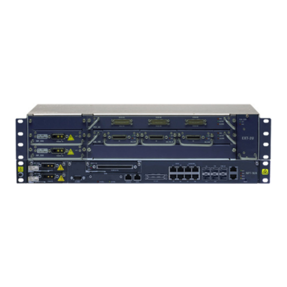
Page 19: Ext-2U Expansion Unit
Introduction The NPT-1020 can be fed by 24 VDC, -48 VDC, or 94-240 VAC. In DC power feeding, two INF modules can be configured in two power supply module slots for redundant power supply, or one double slot INF module with dual-feeding can be configured. -
Page 20: Figure 2-4: Ext-2U Slot Layout
NPT-1020 Installation and Maintenance Manual Introduction Three multipurpose slots (ES1 to ES3) for any combination of extractable traffic cards. PCM, TDM, ADM, Ethernet, and CES traffic are all handled through cards in these traffic slots. All interfaces are configured through convenient SFP modules, supporting up to 2.5G or 2GbE traffic per slot. Each slot in the EXT-2U has a TDM capacity of up to 16 x VC-4s;... -
Page 21: Before You Start
This chapter contains important information that will help you carry out a safe and trouble-free installation. 3.1.1 Outline of the Installation Procedure The main steps involved in the installation of NPT-1020 equipment are described in the following table. Consult your site installation plans for specific details. - Page 22 VDF to the interfaces on the front panel of the SM_10E/EM_10E module. Note: The DDF can be installed on the same rack as the NPT-1020 shelf, or on a different rack. 15 Connect management cables between the equipment installed in the Equipment Installation rack and the management station.
-
Page 23: Site Preparation
Types of interfaces used at the site (optical, electrical, management, alarm monitoring, and so on) Work and equipment safety requirements 3.2.1 Environmental Requirements The environmental conditions listed in the following table are applicable to NPT-1020 equipment and must be ensured at the installation site. Table 3-2: Environmental requirements Parameter Compliance requirements... -
Page 24: Power Sources
ICP_MCP30 3.2.3 Power Sources NPT-1020 platforms can be powered by DC sources complying with the applicable sections of ETSI 300 132-2 and the SELV or TNV requirements of EN 60950. The nominal supply voltage is -48 VDC (positive-lead grounded). However, the allowed supply voltage range is -40.5 VDC to -60 VDC. Two separate DC power sources must be available for redundancy. -
Page 25: Cleaning Optical Connectors
Open frame top and bottom, facilitating easy leading of cables from suspension floors and/or ceiling ladders Front door mountable for left or right opening NPT-1020 equipment racks can be installed on wooden, concrete, or floating floors, or suspended from overhead mountings. ECI Telecom Ltd. Proprietary... -
Page 26: Typical Npt-1020 Installation
Leave at least 50 mm of free space between the NPT-1020 shelf and its FST, and another 50 mm free between the FST and the next NPT-1020 shelf. -
Page 27: Preparing Cables And Fibers
OTE: This section provides information for preparing cables and optical fibers. The necessary cables can be ordered from ECI. For details, contact ECI’s Customer Support team or your ECI sales representative. Before you start: The following main types of cables are required for installing the NPT-1020: Grounding cables DC power cables... -
Page 28: Grounding Cables
NPT-1020 Installation and Maintenance Manual Before You Start Some of these cables are supplied as part of the NPT-1020 equipment, while others must be prepared on site or ordered separately from ECI. In the following sections, you will find information about the cables, and how to prepare them on site, where relevant. -
Page 29: Alarm Cables
2 V, even for cable runs of maximum 30 meters connected to a RAP and providing power to multiple NPT-1020 platforms. When the RAP is used to provide power to a single NPT-1020 platform, lower-lead gauges may be used, as follows: For runs not exceeding 20 meters, use 10 mm copper leads. -
Page 30: Tod/1Pps Cable
IEEE 1588v2 standard. If it has balanced (120 Ω) G.703 interfaces, a multi twisted-pair cable with an RJ-45 connector (supplied by ECI) is used to connect timing signals from the NPT-1020 to the site timing reference distribution subsystems. -
Page 31: Optical Fibers
The optical fibers for connecting to equipment installed in a given rack must enter the rack from the top, be threaded through cable guides running along the rack side rails, and end at the FST. The FST must contain enough fiber length for extracting modules from the NPT-1020 and for replacing fiber in case of damage (splicing repairs). -
Page 32: Work And Equipment Safety
3.6.1 Grounding Requirements All the equipment, including NPT-1020 platforms, ancillary units, and equipment from other vendors, must be properly grounded at all times. Good equipment grounding is necessary to protect personnel and equipment, minimize noise, and allow the discharge of accumulated static charges to earth. -
Page 33: Dc Power Supply Requirements
3.6.2 DC Power Supply Requirements The NPT-1020 and EXT-2U platforms require two power sources with a nominal voltage of -48 VDC. Each power source is protected by a UL-listed circuit breaker installed in the RAP. The required circuit breakers are included in the installation parts kit supplied with the equipment, and therefore, their current rating is in accordance with the order. -
Page 34: Ac Power Supply Requirements
ECI offers the AC_PS-B1U AC/DC converter module for customers who require to power the NPT-1020 from an AC power source. The AC_PS-B1U plugs directly into the NPT-1020 in the PSA and PSB slots (that is regularly used to install two INFs when the platform is powered by DC) and provides up to 180 W. -
Page 35: Figure 3-2: Laser Warning Label
The following labels are affixed to the platform front panel. The labels indicate that the product is classified as a Class 1 Laser Product. Figure 3-2: Laser warning label ASER ARNING: The NPT-1020 is classified as a Class 1 Laser Product. ATTENTION ASER : APPAREIL ’A LASER DE CLASSE 1. -
Page 36: Table 3-11: Lc Transceivers Laser Information Stm-4 Sfp
It is strictly forbidden to interfere with any protective devices and interlocks that are used to prevent direct exposure to the laser beam. 3.6.4.5 Laser Information Information regarding the various optical modules available for the NPT-1020 platform is provided in the following tables. Table 3-11: LC transceivers laser information STM-4 SFP... -
Page 37: Protection Against Electrostatic Discharge
Maximum mean launched power (dBm) Protection against Electrostatic Discharge This section provides guidelines regarding the protection of NPT-1020 equipment and its components against electrostatic discharge (ESD) during handling, packing/unpacking, transport, installation, commissioning, inspections, servicing, and maintenance. Electronic equipment, assemblies, and components that are ESDS (electrostatic discharge sensitive) or include sensitive items are identified by the basic ESD warning symbol shown in the following figure. -
Page 38: Personnel Training
NPT-1020 Installation and Maintenance Manual Before You Start Static electrical charges appear as a result of friction between surfaces of insulating materials or separation of two such surfaces, and may also be induced by electrical fields. Routine activities such as walking across an insulating floor, friction between garment parts, friction between objects, and so on, can easily build up charges to levels that may cause damage, especially when humidity is low. -
Page 39: Work Arrangements Within A Temporary Epa
NPT-1020 Installation and Maintenance Manual Before You Start AUTION: The temporary EPA must be constructed in a way that ensures electrical bonding of all the materials used, and prevents the occurrence of any sudden changes in potential within the EPA that could cause unacceptable voltages or discharges to be applied to ESDS. -
Page 40: Environmental And Health Concerns
NPT-1020 Installation and Maintenance Manual Before You Start Environmental and Health Concerns ECI is committed to achieving high standards of environmental quality and product safety. The International Standardization Organization (ISO) has developed the internationally recognized standards ISO 9001 and ISO 14001. These are quality management standards that are administered by independent accreditation and certification bodies. -
Page 41: Figure 3-4: Pollution Control Logos
NPT-1020 Installation and Maintenance Manual Before You Start Figure 3-4: Pollution control logos OTE: The number in Logo 2 is for illustrative purposes only. When in actual use, the number indicates the corresponding environmental protection use period of the product. -
Page 42: Installing Equipment
OTE: If you are not installing an FST for a particular NPT-1020 shelf, it is recommended that you leave empty space in the rack in case optical modules are added in the future. If you are... - Page 43 Figure 4-1: Typical installation in of a single NPT-1020 in a 2200 ETSI rack For illustrations of installation options, see Installation Options. OTE: The FST should be installed below the NPT-1020. If the EXT-2U is not installed, space above the NPT-1020 should be reserved for the EXT-2U. ECI Telecom Ltd. Proprietary...
-
Page 44: Unpacking And Performing Visual Inspection
Optional SM_10E ICP units Install the NPT-1020 shelf in the rack Install the Dslot modules in the NPT-1020 shelf (if required) Install the SFP modules in the NPT-1020 shelf Install the EXT-2U shelf in the rack (if required) Install the power module in the EXT-2U shelf... -
Page 45: Installation Options
ECI representative immediately. Installation Options It is recommended that NPT-1020 platforms be installed in ECI approved racks. These racks can be installed on wooden, concrete, or suspended floors, or suspended from overhead mountings. The following racks are supported: Standard 19”... - Page 46 ETSI brackets must be ordered separately and replaced in the field. You can install up to eight NPT-1020 platforms in a rack. A typical installation of four NPT-1020 platforms in an ETSI 2200 rack is shown in the following figure.
-
Page 47: Installing Ancillary Units In Racks
The specific units you need to install depend on your site installation plan and may include one or more of the following: RAP unit: For connecting up to four or eight NPT-1020 platforms (NPT-1020 with EXT-2U is counted as ... - Page 48 NPT-1020 Installation and Maintenance Manual Installing Equipment Install circuit breakers. Check power wiring. 4.6.1.1 Preparing DC Input Power Cables OTE: According to accepted industry standards for connecting DC power, the positive lead (+48 V) must be connected with a red cable and the negative lead (-48 V) with a black cable.
-
Page 49: Figure 4-3: Location Of Rap-Bg Grounding Stud
NPT-1020 Installation and Maintenance Manual Installing Equipment 4.6.1.2 Installing the RAP-BG The RAP-BG is attached to the rack side rails at the top position of the rack. To install the RAP-BG Attach the RAP-BG to the side rails and secure it with the four screws, washers, and nuts supplied in ... -
Page 50: Figure 4-5: Connecting Dc Power Cables To The Rap-Bg
Before starting, identify the openings used to route power cables to the RAP-BG. Insert the DC power cable end, terminated with lugs, of the NPT-1020 platform through the opening for platform power cables connecting to source A. If more platforms are installed in the rack, start by connecting the Platform 1 cable. -
Page 51: Figure 4-6: Rap-Bg Platform Power Cable Grounding Screws
RAP-BG side panel. Repeat Step 4 for the grounding lead lug. 10. If additional NPT-1020 platforms are installed in the rack, repeat Steps 2 to 9 for each platform power cable. 11. If an additional power source is used, repeat Steps 2 to 10 to connect the platforms to source B. -
Page 52: Figure 4-8: Rap-Bg Circuit Breaker Installation
The following figure identifies the functions of the power cable connector contacts assembled on the cable end connected to the NPT-1020 platform, as seen when looking into the connector. Figure 4-9: Platform DC input power connector pin functions Make sure the voltage is within the allowed range (-40 VDC to -72 VDC), and that it has the correct polarity. -
Page 53: Installing The Rap-4B
NPT-1020 Installation and Maintenance Manual Installing Equipment Disconnect the RAP-BG input power sources. Reinstall the RAP-BG front cover and fasten it using the two captive screws. 4.6.2 Installing the RAP-4B Before You Start: Before connecting DC power cables, see DC Power Cables. -
Page 54: Figure 4-10: Locating Rap-4B Grounding Stud
NPT-1020 Installation and Maintenance Manual Installing Equipment To prepare a DC power cable: Strip about 22 mm (1 in.) of the red lead jacket. Insert all lead strands into the lug sleeve. Press at two or three different points on the lug sleeve using an appropriate crimping tool and die. -
Page 55: Figure 4-11: Rap-4B With Grounding Cable
NPT-1020 Installation and Maintenance Manual Installing Equipment Connect the lug at one end of the grounding lead to the RAP-4B grounding studs, using spring washers and nuts. Figure 4-11: RAP-4B with grounding cable Connect the two-hole lug at the other end of the grounding lead to the rack's grounding bar. -
Page 56: Figure 4-13: Connecting Dc Power Cables To The Rap-4B
Before starting, identify the openings used to route power cables to the RAP-4B. Insert the DC power cable end terminated in lugs of the NPT-1020 platform through the opening for power cables connecting to source A. If more platforms are installed in the rack, start by connecting the Platform 1 cable. -
Page 57: Figure 4-14: Rap-4B Platform Power Cable Grounding Screws
RAP-4B side panel. Repeat Step 4 for the grounding lead lug. 10. If more NPT-1020 platforms are installed in the rack, repeat Steps 2 to 9 for each platform power cable. 11. If an additional power source is used, repeat Steps 2 to 10 to connect the platforms to source B. -
Page 58: Figure 4-15: Rap-4B Front Cover Removal
NPT-1020 Installation and Maintenance Manual Installing Equipment To install the RAP-4B circuit breakers: If the RAP-4B front panel has not been removed, open the two captive screws fastening it to the chassis and remove the cover. Figure 4-15: RAP-4B front cover removal Identify the circuit breaker corresponding to power circuit A of Platform 1 (the circuit breaker is included in the installation parts kit supplied with the equipment platform;... -
Page 59: Installing The Fst
Install the FST 50 mm below the fiber guide. If additional equipment is installed below it, such as another NPT-1020 platform, an additional 50 mm must be left free between the FST and such equipment. To install the FST in the rack: Attach the FST to the rack rails and secure it using the four supplied screws, washers, and nuts. -
Page 60: Figure 4-18: Threading Optical Fibers In The Fst
NPT-1020 Installation and Maintenance Manual Installing Equipment OTE: The FST has two opening positions. The tray latches with a click at the halfway position. Pull it again to open it fully so that you can thread the fibers. Thread the fibers into the FST, as shown in the following figure. -
Page 61: Installing The Odf
NPT-1020 Installation and Maintenance Manual Installing Equipment 4.6.4 Installing the ODF Identify the prescribed ODF locations in the rack before performing the following procedures. The ODF is supplied with two sets of rack mounting brackets: one for 19” and ETSI racks (for both ETSI A and B), and the other for 23”... -
Page 62: Figure 4-21: Odf Open View
NPT-1020 Installation and Maintenance Manual Installing Equipment Figure 4-21: ODF open view Hold the end of the swing-out tray and pull it out to gain access to the ODF components. Open the two cover thumb nuts and remove the protective cover from the ODF splice support. -
Page 63: Installing The Xddf-21 Patch Panel
The NPT-1020 only supports balanced E1s directly. For unbalanced E1s, install the xDDF-21 that provides balanced-to-unbalanced conversion for 21 E1s. The number of xDDF-21 units to be installed with one NPT-1020 unit is based on the number of PME1_21 modules (for the number of unbalanced E1s required). To install an xDDF-21 patch panel: Route the 100-pin SCSI cables leading from the E1 interfaces on the PME1_21 panel along the side of the rack to the location where the xDDF-21 patch panel is to be installed. -
Page 64: Installing The Ac_Conv_Unit
NPT-1020 Installation and Maintenance Manual Installing Equipment To install an SM_10E/EM_10E ICP: Identify the prescribed position of the ICP in the rack in accordance with the rack installation plan. Place the ICP in the prescribed position using the two stabilizing pins to hold it temporarily in place, and then fasten the platform to the rack side rails with four M6 screws, washers, and nuts. -
Page 65: Installing The Npt-1020 Shelf In The Rack
If you install the NPT-1020 in the rack without installing rail stiffeners, the rear side of the NPT-1020 shelf will be slightly lower than the front side, due to the weight of the NPT-1020 shelf. This makes installation of the EXT-2U very difficult. The rail stiffeners make the NPT-1020 level after it is installed in the rack. Two rail stiffeners are shipped along with the NPT-1020 shelf. -
Page 66: Attaching The Npt-1020 Shelf In The Rack
To attach a NPT-1020 shelf to an ECI recommended rack: Identify the prescribed position of the NPT-1020 shelf in the rack in accordance with the rack installation plan. Place the NPT-1020 shelf in the prescribed position using the two stabilizing pins to hold it temporarily in place, and then fasten the shelf to the rack side rails (to the second and third lowest screws in the rail stiffeners) with four M6 screws and washers. -
Page 67: Installing Power Modules In The Npt-1020
4.7.4 Installing Power Modules in the NPT-1020 Each NPT-1020 shelf must have a power module/modules installed in the power module slot(s). The power module slots are identifies as PSA and PSB. There are several options to install power modules in these slots as follows: Installing an INF-B1U in slot PSA and a second one in slot PSB. -
Page 68: Figure 4-26: Installing An Inf-B1U-24V In The Npt-1020
Hold the INF-B1U module extractor and insert the rear end of the module into the card guides. Push the module in until the panel at the front of the module is flush with the front of the NPT-1020 platform. If resistance is felt before the connectors are flush, pull the module out and repeat the procedure. -
Page 69: Figure 4-27: Installing An Inf-B1U-D In The Npt-1020
Hold the INF-B1U-D module extractor and insert the rear end of the module into the card guides. Push the module in until the panel at the front of the module is flush with the front of the NPT-1020 platform. If resistance is felt before the connectors are flush, pull the module out and repeat the procedure. -
Page 70: Installing Tslot Modules
Hold the AC_PS-B1U module extractor and insert the rear end of the module into the card guides. Push the module in until the panel at the front of the module is flush with the front of the NPT-1020 platform. If resistance is felt before the connectors are flush, pull the module out and repeat the procedure. -
Page 71: Installing Sfp Modules
Hold the Tslot module handle and insert the rear end of the module into the module guides. Push the module in until the front of the module is flush with the front of the NPT-1020 shelf. If resistance is felt, pull the module out and repeat the procedure. -
Page 72: Installing The Ext-2U Platform In The Rack
Installing the EXT-2U Platform in the Rack EXT-2U is an expansion unit which can be added on top of the NPT-1020 to provide enhanced capacity and a rich feature list. If you need more add-drop capacity and additional functionality, such as Ethernet L2 and PCM, an EXT-2U can be added. -
Page 73: Installing The H Connector
The EXT-2U platform is mounted on top of the NPT-1020 platform using the H connector. You need an EXT-2U installation kit to install the EXT-2U on the NPT-1020. This is shipped as part of the EXT-2U platform package. The kit includes the EXT-2U TO NPT-1020/NPT-1200 CONNECTION SPEC. (DWG NO. - Page 74 To install the EXT-2U platform on the NPT-1020 platform: Fasten the two pilot pins for the EXT-2U onto the cover by hand. Mount the EXT-2U on the NPT-1020 using the vertical pilot pins and holes at the bottom of the EXT-2U.
-
Page 75: Disassembling The Ext-2U From The Npt-1020
4.8.3 Disassembling the EXT-2U from the NPT-1020 The following is the correct way to disassemble the EXT-2U from the NPT-1020. The EXT-2U is attached to the NPT-1020 with five snap rivets. You must first remove these rivets before removing the EXT-2U. It is recommended to use a thin flat tool (like a screwdriver) to raise the rivet caps first, and then remove them. -
Page 76: Attaching The Ext-2U Shelf To The Rack
Disassemble the pin guides and the H connector from the NPT-1020. 4.8.4 Attaching the EXT-2U Shelf to the Rack The EXT-2U platform can be mounted in the rack after it has been assembled with the NPT-1020 or added to a NPT-1020 platform already mounted in the rack. -
Page 77: Identifying Slots In The Ext-2U
NPT-1020 Installation and Maintenance Manual Installing Equipment 4.8.5 Identifying Slots in the EXT-2U The layout of the EXT-2U is depicted in the following figures. Figure 4-36: EXT-2U regular slots layout Figure 4-37: EXT-2U slot layout with extended ES 3# The figures show two possible arrangements for the EXT-2U slots layout. The upper figure shows the regular layout of the EXT-2U. -
Page 78: Installing An Fcu_E2U In The Ext-2U
NPT-1020 Installation and Maintenance Manual Installing Equipment 4.8.6 Installing an FCU_E2U in the EXT-2U The EXT-2U platform must have one Fan Control module (FCU_E2U) installed in the FCU slot, and is shipped with the module already installed. The following procedure therefore describes replacing the module. -
Page 79: Figure 4-39: Installing An Extension Card In The Ext-2U
Secure the card in place by fastening its two captive screws. OTE: Extension cards support live insertion. They can be installed at any time without affecting the existing traffic running on the NPT-1020 or EXT-2U. ECI Telecom Ltd. Proprietary 4-38... -
Page 80: Installing A Power Module In The Ext-2U
NPT-1020 Installation and Maintenance Manual Installing Equipment 4.8.8 Installing a Power Module in the EXT-2U The EXT-2U platform must have power modules installed in the power module slot. Two INF_E2Us can be configured according to the site installation plan. The EXT-2U platform is always shipped with the power module slot empty. - Page 81 NPT-1020 Installation and Maintenance Manual Installing Equipment SM_OMNI_E SM_C37.94S Figure 4-41: Installing traffic module in the SM_10E/EM_10E To install a traffic module in the SM_10E/EM_10E card: Loosen the two screws fastening the blank panel to the SM_10E/EM_10E front, and remove it.
-
Page 82: Connecting Fibers And Cables To The Npt-1020 Shelf
Follow the procedure below to connect power cables to a DC power source. To connect power cables: Route the power cables leading from the RAP along the side of the rack to the appropriate NPT-1020 and EXT-2U shelves. OTE: For further details about the RAP installation procedure, see Installing the RAP-BG and Installing the RAP-4B. -
Page 83: Connecting An Ac Power Cable To The Npt-1020
Installing Equipment 4.9.2 Connecting an AC Power Cable to the NPT-1020 If the NPT-1020 is fed by an AC source it must be equipped with an AC_PS-B1U module. The connection of the AC power is described below. To connect an AC power source to the AC_PS-B1U: Insert the female 3-pin connector into the corresponding connector on the AC_PS-B1U. -
Page 84: Routing And Connecting Electrical Interface Cables To The Npt-1020
NPT-1020 Panel The NPT-1020 has 21 x E1 interfaces on its front panel, connected through a 2 x 50-pin SCSI connector marked E1 (1-21). The connection to these interfaces is made by a multipair cable (2 x 21 120 Ω twisted pairs) terminated with a 2 x 50-pin SCSI male connector (the other side of the cable is open and connected to the customer's DDF). - Page 85 Use cable ties as required to fasten the cable to the rack side rails. Use a cabling diagram of the site to associate the NPT-1020's E1 connector with the appropriate DDF connections.
-
Page 86: Figure 4-42: Pme1_63 Traffic Cable
NPT-1020 Installation and Maintenance Manual Installing Equipment AUTION: Do not exert excessive tightening torque to secure the cable connector, as this may damage the PME1_21. To connect E1 cables between the xDDF-21 and the external DDF: Coaxial cables are used for connecting unbalanced E1s between the xDDF-21 and the external DDF. A ... - Page 87 NPT-1020 Installation and Maintenance Manual Installing Equipment The three 30 AWG cable pairs connect on one side to the double 136-pin VHDCI connector and on the other side to the conversion box. The conversion box connects the three 30 AWG cable pairs and three pairs of 26 AWG cables, making the wire-size conversion.
-
Page 88: Figure 4-43: Pme1_63 Traffic Cable Installation
NPT-1020 Installation and Maintenance Manual Installing Equipment Figure 4-43: PME1_63 traffic cable installation To route the PME1_63 traffic cable: Bend the cables from the connector installed in the previous procedure towards the cable guide and holder unit (see the preceding figure). -
Page 89: Routing And Connecting Data Interface Cables To Ethernet Interfaces
Bend the cable and thread it through the side cable guides of the rack so that the cable connector is positioned at the level of the NPT-1020 unit. Use cable ties as required to fasten the cable to the rack side rails. -
Page 90: Routing And Connecting Electrical Cables For Pcm Interfaces
NPT-1020 Installation and Maintenance Manual Installing Equipment 4.9.6 Routing and Connecting Electrical Cables for PCM Interfaces This section describes the connection of PCM interface electrical cables to the VDF and ICPs. 4.9.6.1 Routing and Connecting Electrical Cables for PCM Interfaces to the VDF Each type of SM_10E/EM_10E traffic module uses a SCSI-36 connector for its external interfaces. - Page 91 NPT-1020 Installation and Maintenance Manual Installing Equipment To connect PCM traffic cables to an ICP: Arrange the PCM traffic cables and route them to the rack side rails. Pull one end of each PCM traffic cable to the level of the SM_10E/EM_10E card.
- Page 92 NPT-1020 Installation and Maintenance Manual Installing Equipment 2W E&M 4W E&M Codirectional 64 Kbps Different interface types can use different wires in this cable. Use the information in Connection Data to identify the wires for each type of interface.
-
Page 93: Connecting The Timing (Clock) Cable
To connect the timing cable to the NPT-1020: Route the timing cable along the side of the rack to the appropriate NPT-1020 platform. Connect the free end of the cable in accordance with the rack installation plan and the cable tags to the T3/T4 connector on the NPT-1020 front panel. -
Page 94: Npt-1020 Wall-Mounted Installations
NPT-1020 Wall-Mounted Installations Overview In addition to the regular installation of the NPT-1020 in different racks, ECI offers two options for wall-mounted installations: Wall-mounted cabinet Wall-mounted frame These options are ideal for installations in small businesses or home offices (SOHO). -
Page 95: Installing The Npt-1020 In A Wall-Mounted Cabinet
The installation of a NPT-1020 in a wall-mounted cabinet includes the following stages: Installing the wall-mounted cabinet rear panel Installing cabling accessories Installing the NPT-1020 platform and ancillary equipment (three DDFs or two DDFs and an AC CONV unit) Connecting cables and fibers to the NPT-1020 platform and ancillary equipment... -
Page 96: Preparing The Rear Panel Holes
NPT-1020 Installation and Maintenance Manual NPT-1020 Wall-Mounted Installations The wall-mounted cabinet interior components are shown in the following figure. Figure 5-2: Wall-mounted cabinet interior components 5.4.1 Preparing the Rear Panel Holes To prepare the rear panel holes: Identify the prescribed location of the rear panel on the wall. -
Page 97: Figure 5-3: Preparing The Rear Panel Holes
NPT-1020 Installation and Maintenance Manual NPT-1020 Wall-Mounted Installations Place the enclosed drilling template on the prescribed position; align it at the desired height using a bubble level and secure it to the wall. Figure 5-3: Preparing the rear panel holes Drill four holes using the four upper holes in the template (the cabinet is 6U high). -
Page 98: Installing The Rear Panel
NPT-1020 Installation and Maintenance Manual NPT-1020 Wall-Mounted Installations 5.4.2 Installing the Rear Panel ANGER: The operator is responsible for the secure mounting of the cabinet to the wall, using appropriate installation materials. OTE: Use only the self-tapping screws, supplied with the cabinet. -
Page 99: Attaching The Support Rails
NPT-1020 Installation and Maintenance Manual NPT-1020 Wall-Mounted Installations 5.4.3 Attaching the Support Rails The rear panel has four holes for attaching support rails. To attach the support rails: Identify the four holes in the rear panel for the support rails (see the following figure). -
Page 100: Installing The C-Rail
NPT-1020 Installation and Maintenance Manual NPT-1020 Wall-Mounted Installations Fasten the extrusion with the screws using a hex wrench. Repeat Steps 2 and 3 for the second extrusion. 5.4.5 Installing the C-Rail A C-rail (so called because of its C shape) is attached to the upper side of the rear panel. The C-Rail helps support various cabling accessories. -
Page 101: Installing Cable Guides
NPT-1020 Installation and Maintenance Manual NPT-1020 Wall-Mounted Installations Figure 5-9: Cabling accessories installed in the cabinet 5.5.1 Installing Cable Guides Cable guides are installed on both sides of the vertical extrusions and help route cables neatly in the cabinet. ECI Telecom Ltd. Proprietary... -
Page 102: Figure 5-10: Cabling Accessories
NPT-1020 Installation and Maintenance Manual NPT-1020 Wall-Mounted Installations Before you start: Identify the cable guide with its components according to the following figure; the cable guide has an installation bracket attached. Figure 5-10: Cabling accessories To install the cable guides: Align the cable guide on the side of the extrusion to an approx. -
Page 103: Attaching Cable Clamping Bars
NPT-1020 Installation and Maintenance Manual NPT-1020 Wall-Mounted Installations 5.5.2 Attaching Cable Clamping Bars Two cable clamping bars are attached to the C-rail. They help route cables neatly in the cabinet. To attach the cable clamping bars: Identify the cable clamping bar according to the figure Cabling accessories. -
Page 104: Ddf 21 E1S Unit
NPT-1020 Installation and Maintenance Manual NPT-1020 Wall-Mounted Installations Right lower support rail outer hole, near the rear panel. Right upper support rail inner hole, near the front. DDF 21 E1s Unit The DDF unit supports connection of up to 21 E1 lines. The terminal blocks connect the equipment side and the customer's E1 interfaces. -
Page 105: Figure 5-12: Installing The Brackets For Etsi Installation
NPT-1020 Installation and Maintenance Manual NPT-1020 Wall-Mounted Installations To attach the brackets for ETSI installation: Unscrew the six M2.5 x 6 screws (three on each side) attaching the brackets to the DDF tray. Keep the screws for the next steps. -
Page 106: Wiring The E1 Cables To The Ddf
NPT-1020 Installation and Maintenance Manual NPT-1020 Wall-Mounted Installations To attach the connection blocks: Place the block in front of the corresponding DDF bushing pair as shown in the following figure. Figure 5-13: Attaching the connection blocks Push the block on the bushings to snap it on. -
Page 107: Installing The Npt-1020 And Three Ddfs
Connect each pair to the corresponding block contacts according to the wiring diagram. Installing the NPT-1020 and Three DDFs In this configuration the NPT-1020 and three DDF units are installed in the cabinet. Installation includes the following steps: Installing clip nuts... -
Page 108: Installing Clip Nuts For The Npt And Ddfs
NPT-1020 Installation and Maintenance Manual NPT-1020 Wall-Mounted Installations 5.7.1 Installing Clip Nuts for the NPT and DDFs Sixteen clip nuts, eight on each side, are attached to the two vertical extrusions to support the NPT-1020 and DDFs. To install the clip nuts: Identify the locations of the clip nuts according to the following figure: the numbers refer to the distance in mm of the clip nuts from the lowest hole (0 mm). -
Page 109: Installing The Npt-1020 Platform
Repeat Steps 1 and 2 for the other two DDFs. Installing the NPT-1020, Two DDFs, and an AC CONV Unit In this configuration, the NPT-1020, two DDFs, and an AC CONV unit are installed in the cabinet. Installation includes the following steps: Installing clip nuts... -
Page 110: Figure 5-16: Clip Nuts Distance In Mm (Npt-1020, Two Ddfs, Ac Conv Unit)
5.8.1 Installing Clip Nuts for the NPT-1020, DDFs, and AC CONV Unit Sixteen clip nuts, eight on each side, are attached to the two vertical extrusions to support the NPT-1020, DDFs, and AC CONV unit installation. To install the clip nuts: Identify the locations of the clip nuts according to the following figure. -
Page 111: Installing The Npt-1020 Platform
The NPT-1020 platform is installed at the bottom of the cabinet. To install the NPT-1020 platform: Identify the prescribed position of the NPT-1020 in the cabinet according to the figure in the topic Installing the NPT-1020, Two DDFs, and an AC CONV Unit. -
Page 112: Routing And Connecting Cables And Fibers In The Cabinet
NPT-1020 front panel. For instance, power connectors are on the left side of the NPT-1020, so the power cables are routed on the left side beneath the platform. The cables are then attached to the cable guide on the left side of the cabinet with cable ties. -
Page 113: Connecting Power Cables
To connect power cables: Connect the connector at the end of the power cable to the power connector on the NPT-1020, and fasten it with its two screws. Grasp the connector at the other end of the power cable, and thread it through the space beneath the platform. -
Page 114: Figure 5-18: Wall-Mounted Cabinet Cables Routing Front View
NPT-1020 Installation and Maintenance Manual NPT-1020 Wall-Mounted Installations Figure 5-18: Wall-mounted cabinet cables routing front view Repeat Steps 1 and 2 for the second power cable to be connected to the corresponding connector on the platform. Bend the cables and thread them through the left cable guide of the cabinet. -
Page 115: Connecting Alarm Cables
(maximum blade size 0.6). Set the tightening torque to 40 N cm to 44 N cm. Bend the cable and route it above the NPT-1020 and through to the left side cable guide. Route the cable near the left cable clamp on the C-rail. -
Page 116: Connecting Optical Fibers
NPT-1020 Wall-Mounted Installations 5.10.3 Connecting Optical Fibers All optical fibers in the NPT-1020 platform are connected to the LC connectors on the SFP/XFP transceivers. Optical fibers must be routed through the flexible tube attached to the right side of the cabinet. -
Page 117: Routing And Connecting Coaxial Cables
OTE: The cable route described above assumes that the E3/DS-3 or electrical STM-1 module is installed on the left side of the NPT-1020. If it is installed on the right side, perform the same procedural steps but on the cabinet's right side. -
Page 118: Connecting Timing (Clock) Cables
Connect the management station cable to the MNG connector of the platform in accordance with the frame installation plan and the cable tags. Thread the cable through the space above the NPT-1020 and the left side of the cabinet. Bend the cable and thread it through the left side cable guide of the cabinet. -
Page 119: Installing The Wall-Mounted Cabinet Covers And Door
In a similar way, cable connected to connector on the right side of the NPT-1020, for instance T3/T4 (clock) cable should be routed from the right side of the NPT-1020 in the space between the unit and the unit installed above it. Then the cable should be passed through the right cable guide, routed up to the right cable clamp bar and attached to it with cable ties. -
Page 120: Installing The Side Covers
NPT-1020 Installation and Maintenance Manual NPT-1020 Wall-Mounted Installations Figure 5-21: Connecting grounding cables To install the top cover: Slide the top cover while inserting the two protrusions on the cover into the opposite housing on the rear panel (see the figure Installing top and bottom covers). -
Page 121: Installing The Front Door
NPT-1020 Installation and Maintenance Manual NPT-1020 Wall-Mounted Installations Figure 5-23: Connecting grounding cables To install the left side cover: Slide the left side cover into place while inserting the two protrusions on the cover into the opposite housing on the rear panel (see the figure Installing side covers). -
Page 122: Wall-Mounted Frame
Figure 5-25: Connecting the door grounding cable 5.13 Wall-Mounted Frame The wall-mounted frame is another option for installing the NPT-1020 and accessories in SOHO. The wall-mounted frame is 300 mm high, 600 mm wide, and 350 mm deep. The front transparent cover protects the NPT-1020 traffic and fiber cables against unintended disconnection or bending. -
Page 123: Figure 5-26: Wall-Mounted Frame Installation
NPT-1020 Installation and Maintenance Manual NPT-1020 Wall-Mounted Installations Figure 5-26: Wall-mounted frame installation The lower cable support is attached to the frame side in holes 5 and 8 from the bottom as shown in the figure above. Attach the lower cable support to the frame with four M3 Phill. screws, spring washers, and flat washers. -
Page 124: Attaching The Fiber Guide Tube
NPT-1020 Installation and Maintenance Manual NPT-1020 Wall-Mounted Installations 5.14.2 Attaching the Fiber Guide Tube The fiber guide tube facilitates fiber routing in the frame. It is attached to the right side of the frame and fastened to the cable supports. -
Page 125: Attaching The Wall-Mounted Frame
Attach the frame to the wall and fasten it with four screws. 5.15 Installing the NPT-1020 and Accessories in the Wall-Mounted Frame ECI offers four configurations for installing the NPT-1020 and various accessories in the wall-mounted frame. You can select the most suitable configuration according to your application. The configurations are: NPT-1020 and three DDFs (option 1) ... -
Page 126: Installing The Npt-1020 And Three Ddfs (Option 1)
To install the NPT-1020: Identify the prescribed position of the NPT-1020 in the wall-mounted frame. Attach the NPT-1020 to the frame with four M6 Phill. screws and flat washers. Fasten the NPT-1020 to the frame. To install the three DDFs: Identify the prescribed position of the lower DDF in the wall-mounted frame. -
Page 127: Installing The Npt-1020, A Ddf, And A Rap-Bg (Option 2)
5.15.2 Installing the NPT-1020, a DDF, and a RAP-BG (Option To install the NPT-1020: Identify the prescribed position of the NPT-1020 in the wall-mounted frame. Attach the NPT-1020 to the frame with four M6 Phill. screws and flat washers. Fasten the NPT-1020 to the frame. To install the DDF: Identify the prescribed position of the DDF in the wall-mounted frame. -
Page 128: Installing The Npt-1020 And A Ddf (Option 5)
5.15.4 Installing the NPT-1020 and a DDF (Option 5) To install the NPT-1020: Identify the prescribed position of the NPT-1020 in the wall-mounted frame. Attach the NPT-1020 to the frame with four M6 Phill. screws and flat washers. Fasten the NPT-1020 to the frame. To install the DDF: Identify the prescribed position of the DDF in the wall-mounted frame. -
Page 129: Installing The Cover Holders
NPT-1020 Installation and Maintenance Manual NPT-1020 Wall-Mounted Installations 5.16.1 Installing the Cover Holders Four holders are installed in front of the wall-mounted frame. To install the cover holders: Identify the cover holder positions on the frame according to the following figure. -
Page 130: Attaching The Transparent Protection Cover
NPT-1020 Wall-Mounted Installations 5.16.2 Attaching the Transparent Protection Cover OTE: The protection cover is attached in place only after all cabling functions of the NPT-1020 and the other equipment, described in Routing and Connecting Cables and Fibers in Frame, have been completed. -
Page 131: Routing And Connecting Cables And Fibers In The Frame
NPT-1020 front panel. For instance, power connectors are on the left side of the NPT-1020, so power cables are routed on the left side beneath the platform. The cables are then attached to the cable supports on the left side of the frame with cable ties. -
Page 132: Connecting Power Cables
To connect a power cable: Connect the connector at the end of the power cable to the power connector of the NPT-1020 and fasten it with its two screws. Grasp the connector at the other end of the power cable and thread it through the space between the platform and the frame. -
Page 133: Connecting Alarm Cables
(maximum blade size 0.6). Set the tightening torque to 40 N cm to 44 N cm. Bend the cable and route it above the NPT-1020 and adjacent to the left side cable supports. Use cable ties as required to fasten the cable to the cable supports. -
Page 134: Routing And Connecting Electrical Traffic Cables
NPT-1020 Wall-Mounted Installations 5.18.4 Routing and Connecting Electrical Traffic Cables Multipair cables are used to connect the balanced E1 (2 Mbps) interfaces located on the NPT-1020 or on E1 modules installed in it. Each cable consists of a total of 21 E1 twisted pairs per cable (transmit or receive). The cable end connecting to the NPT-1020 or to the E1 module is terminated with an appropriate male connector. -
Page 135: Connecting Timing (Clock) Cables
Bend the cable and thread it through the space above the NPT-1020 and the left side of the frame. Use cable ties as required to fasten the cable to the frame cable supports. -
Page 136: Commissioning Tests
This check is performed to confirm that the required cards and modules have been installed in each site, and to record their options, revisions, boot version, and serial numbers. The following table provides a typical form for recording the cards and modules installed in a NPT-1020 shelf. -
Page 137: Visual Inspection And Mechanical Checks
After completing the visual inspection tasks (items 1 through 18 in the following table), power on the NPT-1020 platform to perform an additional set of acceptance tests (items 15 through 19 in the following table). These tests check the functions needed for carrying out the network commissioning tests. Consult the NPT Product Line General Description and the NPT Product Line Reference Manual for a description of the various card indicators and their functions. -
Page 138: Measuring Optical Levels
Power on the platform. Check the proper operation of both RAP power sources by disconnecting one source at a time. Check the communication between the NPT-1020 platform and the LCT-APT via the MNG Ethernet interface. Check the proper operation of all fans. -
Page 139: Platform Power-On Test Procedure
NPT-1020 Installation and Maintenance Manual Commissioning Tests The measured power levels: Must be within the range of minimum and maximum levels specified in the NPT Product Line General Description for the transceiver plug-in type installed on the corresponding port. -
Page 140: Network Timing Synchronization Test
Inject error BIP error 6.3.2 Network Timing Synchronization Test This test checks that the NPT-1020 NEs synchronize properly and switch to the next priority clock source when a failure occurs. To perform network timing synchronization test: Define one NE as the (internal) timing source to which all other NEs are synchronized. This test can be done with an external timing source, if requested. -
Page 141: Loss Of Signal (Los) Detection Test
6.3.4 Input Sensitivity Test This test verifies that the input sensitivity of the NPT-1020 optical modules is according to specifications. To perform an input sensitivity test: Create one unprotected trail of any rate between two NEs. -
Page 142: Traffic Stability Test
NPT-1020 Installation and Maintenance Manual Commissioning Tests Power on the NE and wait for it to perform the initial download to all cards/modules in the platform. This can take five minutes. Verify that the NE is connected to the management station and that there are no relevant alarms in the test equipment or at the management station. -
Page 143: Severity Assignment Test
Commissioning Tests 6.3.8 Severity Assignment Test This test, which is performed on one NPT-1020 NE, determines the level of urgency accorded to each alarm and creates an alarm-handling protocol. When a fault is detected or removed, the NE updates the status of the LEDs and reports the alarm activation or clearing to the management station. -
Page 144: Maintenance Action Test
NPT-1020 Installation and Maintenance Manual Commissioning Tests 6.3.10 Maintenance Action Test This test verifies that maintenance actions can be performed in the NPT-1020 NEs using the management system. This procedure tests a near-end loopback, forced PDH AIS, forced low-rate RDI, forced high-rate RDI, and forced MS-RDI. -
Page 145: System Recovery And Reset Tests
NPT-1020 Installation and Maintenance Manual Commissioning Tests OTE: Measured latency is for both the forward and return paths. For a single path, the latency is 50% of the measured value. The latency test is dependent on the throughput results. For example, if 10 Mbps is tested ... -
Page 146: Stability Test
NPT-1020 Installation and Maintenance Manual Commissioning Tests [(input fps) - (output fps)] * 100 / (input fps) fps = frames per second For example, for a 100 Mbps test using 5 * VC-12 = 10 Mbps, with input fps = 148810 and output fps = 14881, the frame loss is: 148810 - 14881 = 133929 (a 90% loss). -
Page 147: Maintenance
Preventive Maintenance The purpose of preventive maintenance activities is to keep the NPT-1020 hardware in good condition, and detect and correct as soon as possible any condition that may lead to deterioration and equipment malfunction. -
Page 148: Onsite Troubleshooting
Many problems can be detected via the various indicators available on the NPT-1020 system components. This chapter assumes familiarity with the NPT-1020, with SDH data, and with the LightSoft and EMS-APT management stations. See the respective user manual for details on the various capabilities of the management stations and for instructions on performing the necessary activities. -
Page 149: Troubleshooting Power Problems
Check the circuit breakers in the RAP and replace if necessary. Equipment problem Check the voltage at the NPT-1020 and EXT-2U end of each power cable. Replace the cable or repair the RAP if there is no voltage present. -
Page 150: Troubleshooting Using Component Indicators
NPT-1020 Installation and Maintenance Manual Maintenance Symptoms Probable cause Corrective actions All LEDs and fans in No input power to the Check the corresponding circuit NPT-1020 off corresponding unit breaker in the RAP, and reset any tripped breaker. Check the circuit breakers in the ... -
Page 151: Table 7-3: General Troubleshooting Procedures For Npt-1020 Power-On
NPT-1020 Installation and Maintenance Manual Maintenance Table 7-3: General troubleshooting procedures for NPT-1020 power-on Symptom Probable cause Corrective actions Indicators on MXC panel FAIL Blink Boot selection Power off and wait a few minutes before non-existent or powering on again. - Page 152 NPT-1020 Installation and Maintenance Manual Maintenance Symptom Probable cause Corrective actions Indicators on MXC panel FAIL Blink Blink Nonexecutable Power off and wait a few minutes before application software powering on again. When the ACT indicator is off and the MNR ...
- Page 153 Power off and wait a few minutes before unsuccessfully powering on again. Wait a minute at most. The ACT indicator should flash and the FAIL indicator should be off. If not, replace the NPT-1020 unit. ECI Telecom Ltd. Proprietary...
-
Page 154: Table 7-4: General Troubleshooting Procedures For Npt-1020
Table 7-4: General troubleshooting procedures for NPT-1020 No. Symptoms Probable cause Corrective actions Green ACT indicator not Damaged software or Perform a warm reset on the NPT-1020 by flashing, and the status defective card pressing the RST button. always on If the ACT indicator starts to flash, keep ... -
Page 155: Table 7-5: General Troubleshooting Procedures For Optical Transceiver Plug-Ins
10/100 Mbps, it is in normal state. If the speed status in the LCT-APT is 10/100 Mbps, the NPT-1020 or indicator is defective. Replace the NPT-1020 unit. Table 7-5: General troubleshooting procedures for optical transceiver plug-ins No. Symptom... - Page 156 power. If the output optical power is not within the range of minimum and maximum levels specified in the NPT-1020 System Specifications during a 90-second period, the problem is in the transmit side of the transceiver. Remove and reinsert the transceiver.
- Page 157 If the ACT indicator is still off, replace the NPT-1020 unit. Red FAIL indicator on or Defective card/module Perform a warm reset on the NPT-1020 by not turning off after pushing the RST button. power-on and reset If the FAIL indicator is on after reset, ...
-
Page 158: Table 7-7: Troubleshooting Procedures For Smd1B/Sms4 Cards
If the ACT indicator is still off, replace the NPT-1020 unit. Red FAIL indicator on Damaged software or Perform a warm reset on the NPT-1020 by or not turning off after defective card/module pushing the RST button. power-on and reset If the FAIL indicator is on after reset, ... -
Page 159: Table 7-9: Special Troubleshooting Procedures For P345_3E Cards
is activated, the ACT indicator should be on and the FAIL indicator should be off. Damaged software or Perform a warm reset on the NPT-1020 by defective card/module pushing the RST button. If the FAIL indicator is on after reset, ... -
Page 160: Replacing Cards And Modules
BIT fail Replace the module. after power-on or reset Replacing Cards and Modules The following sections provide procedures for replacing cards and modules in the NPT-1020. 7.5.1 Safety and Workmanship Refer to Before You Start for safety and workmanship instructions. -
Page 161: Replacing Tslot Cards
Insert the rear end of the replacement card into the corresponding card guides. Push the replacement card in until the front panel of the card is flush with the front of the NPT-1020 platform. If resistance is felt before the connectors are flush, pull the card out and repeat the procedure. -
Page 162: Replacing Eslot Cards
NPT-1020 Installation and Maintenance Manual Maintenance 7.5.3 Replacing Eslot Cards OTE: All Eslot cards support live insertion. There is no need to power-off the NPT-1020 or the EXT-2U units when replacing them. To replace an Eslot card in the EXT-2U platform: Mark each cable connected to the Eslot card for identification purposes. -
Page 163: Replacing Icps For The Sm_10E/Em_10E
Push the replacement module in until the front panel of the module is flush with the front of the NPT-1020 or EXT-2U platform. If resistance is felt before the connectors are flush, pull the module out and repeat the procedure. -
Page 164: Replacing Sfp/Csfp/Sfp+ Transceivers
NPT-1020 Installation and Maintenance Manual Maintenance 7.5.7 Replacing SFP/CSFP/SFP+ Transceivers ECI supplies field-replaceable SFP/CSFP/SFP+ transceivers in all optical and electrical STM-1 interfaces. Hot swapping is allowed, provided you observe the safety precautions described in Before You Start during the replacement. -
Page 165: Connection Data
Connection Data Overview This chapter provides connection data for the user connectors located in the NPT-1020/EXT-2U platforms and associated ancillary equipment supplied by ECI. Any connectors not described in this appendix are reserved for use by ECI technical support personnel and/or future expansion, and therefore no user equipment may be connected to them. -
Page 166: T3/T4 Timing Connector
NPT-1020 Installation and Maintenance Manual Connection Data T3/T4 Timing Connector The T3/T4 timing connector is an RJ-45 connector located on the NPT-1020 panel and designated T3/T4. The interface includes a group of lines that are usually connected to the site timing reference distribution subsystem: Clock input (T3 2.048 Mbps or 2.048 MHz signal, ITU-T Rec. -
Page 167: 1Pps/Tod Timing Connector
Input/Output Alarms Connector The Alarms connector, designated ALARMS, is a 15-pin D-type male connector on the NPT-1020 panel that provides an alarm interface connecting to the RAP. The connector supports two groups of lines: Four external alarm input lines. The alarm input lines are monitored by the NPT-1020 management ... -
Page 168: Figure 8-5: Alarms Connector, Pin Identification
NPT-1020 Installation and Maintenance Manual Connection Data ECI offers appropriate cables for each of these configurations. The following figure identifies the connector pins, as seen when looking into the connector. The following table lists the connector pin assignment. Figure 8-5: Alarms connector, pin identification... - Page 169 Connection Data NPT-1020 Built-in E1 Connector The NPT-1020 provides 21 built-in balanced E1 tributary interfaces through a twin 68-pin VHDCI female connectors. The connector serves the 21 × E1 receive and transmit signals. The following figure identifies the connector pins, as seen when looking into the connector. The following tables list the pin assignment for the connectors.
- Page 170 NPT-1020 Installation and Maintenance Manual Connection Data P2 pin Name Function Direction Wire color Not connected Not connected TTIP6 Transmit, tributary 6, wire A Output Blue TRING6 Transmit, tributary 6, wire B Output Blue/Gray ring TTIP5 Transmit, tributary 5, wire A...
- Page 171 NPT-1020 Installation and Maintenance Manual Connection Data P2 pin Name Function Direction Wire color Not connected Not connected RRING8 Receive, tributary 8, wire B Input Orange/Brown ring RTIP8 Receive, tributary 8, wire A Input Green/Brown ring RRING7 Receive, tributary 7, wire B...
- Page 172 NPT-1020 Installation and Maintenance Manual Connection Data Table 8-5: NPT-1020 E1 connector (P1), pin assignment P1 pin Name Function Direction Wire color Not connected RRING12 Receive, tributary 12, wire B Input Brown/Yellow ring RTIP12 Receive, tributary 12, wire A Input...
- Page 173 NPT-1020 Installation and Maintenance Manual Connection Data P1 pin Name Function Direction Wire color RTIP20 Receive, tributary 20, wire A Input Red/Orange ring RRING21 Receive, tributary 21, wire B Input Yellow/Orange ring RTIP21 Receive, tributary 21, wire A Input Green/Orange ring...
-
Page 174: E1 Connectors On The Pme1_21 And Mse1_16
NPT-1020 Installation and Maintenance Manual Connection Data P1 pin Name Function Direction Wire color TRING18 Transmit, tributary 18, wire B Output Brown/Pink ring TTIP18 Transmit, tributary 18, wire A Output Red/Pink ring TRING19 Transmit, tributary 19, wire B Output Orange/Pink ring... - Page 175 NPT-1020 Installation and Maintenance Manual Connection Data The following figure identifies the connector pins as seen when looking into the connector. The table lists the pin assignment for a typical connector. It also lists the color of the wire connected to the corresponding pin in the cables offered by ECI for connecting between the tributary connector and a distribution frame.
- Page 176 NPT-1020 Installation and Maintenance Manual Connection Data Name Function Direction Wire color TRING10 Transmit, tributary 10, wire B Output Not connected TTIP9 Transmit, tributary 9, wire A Output Orange/Gray ring TRING9 Transmit, tributary 9, wire B Output Orange TTIP8 Transmit, tributary 8, wire A...
- Page 177 NPT-1020 Installation and Maintenance Manual Connection Data Name Function Direction Wire color RRING16 Receive, tributary 16, wire B Input Brown/Blue ring Not connected RTIP15 Receive, tributary 15, wire A Input White/Yellow ring RRING15 Receive, tributary 15, wire B Input Light Gray/Yellow ring...
-
Page 178: Ethernet Interface Connectors
Platform --- Braid Ethernet Interface Connectors The NPT-1020 platform provides 12 traffic Ethernet interfaces on its front panel as follows: 4 x 10/100/1000 BaseT interfaces (left-most ports marked P1 to P4) based on RJ-45 connectors with 4 x 10/100/1000 BaseT interfaces (ports marked P5 to P8) based on RJ-45 connectors without PoE ... -
Page 179: Pm345_3 Card Connection Data
NPT-1020 Installation and Maintenance Manual Connection Data Designation Function Direction TX/RX+ Transmit positive signal/Receive Out/In positive signal Out/In Transmit negative signal/Receive Out/In negative signal 8.10 PM345_3 Card Connection Data The PM345_3 card provides three unbalanced E3/DS-3 tributary interfaces. The E3/DS-3 connectors are coaxial connectors (6 x DIN 1.0/2.3) on the PM345_3 front panel. - Page 180 NPT-1020 Installation and Maintenance Manual Connection Data P2 pin Name Function Direction Wire color TRING11 Transmit, tributary 11, wire B Output Brown/Gray ring Not connected Not connected TTIP10 Transmit, tributary 10, wire A Output TRING10 Transmit, tributary 10, wire B...
- Page 181 NPT-1020 Installation and Maintenance Manual Connection Data P2 pin Name Function Direction Wire color TRING2 Transmit, tributary 2, wire B Output Red/White ring TTIP1 Transmit, tributary 1, wire A Output Orange/White ring TRING1 Transmit, tributary 1, wire B Output Yellow/White ring...
- Page 182 NPT-1020 Installation and Maintenance Manual Connection Data P2 pin Name Function Direction Wire color RRING4 Receive, tributary 4, wire B Input Green/Red ring RTIP3 Receive, tributary 3, wire A Input Blue/Red ring RRING3 Receive, tributary 3, wire B Input Violet/Red ring...
- Page 183 NPT-1020 Installation and Maintenance Manual Connection Data P1 pin Name Function Direction Wire color RTIP16 Receive, tributary 16, wire A Input Red/Blue ring RRING17 Receive, tributary 17, wire B Input Orange/Blue ring RTIP17 Receive, tributary 17, wire A Input Yellow/Blue ring...
- Page 184 NPT-1020 Installation and Maintenance Manual Connection Data P1 pin Name Function Direction Wire color TTIP14 Transmit, tributary 14, wire A Output Red/Violet ring TRING15 Transmit, tributary 15, wire B Output Orange/Violet ring TTIP15 Transmit, tributary 15, wire A Output Yellow/Violet ring...
-
Page 185: Sm_10E/Em_10E Card Connection Data
NPT-1020 Installation and Maintenance Manual Connection Data 8.13 SM_10E/EM_10E Card Connection Data The SM_10E/EM_10E base card does not have any external interfaces. All external interfaces are from the front panel of each type of SM_10E/EM_10E traffic module. The following types of SM_10E/EM_10E traffic... -
Page 186: Connection Data For Sm_Em_24W6E Interfaces
NPT-1020 Installation and Maintenance Manual Connection Data Name Function Direction Wire color Channel 2, wire B Bidirectional Red/Black Channel 3, wire A Bidirectional Orange Channel 3, wire B Bidirectional Orange/Black Channel 4, wire A Bidirectional Yellow Channel 4, wire B... - Page 187 NPT-1020 Installation and Maintenance Manual Connection Data Name Mode Function Direction Wire color Channel 3, Rx, wire B Output Orange/Black Channel 3, wire B Bidirectional Channel 4, Rx, wire A Output Yellow Channel 4, wire A Bidirectional Channel 4, Rx, wire B...
-
Page 188: Connection Data For Sm_V24E Interfaces
NPT-1020 Installation and Maintenance Manual Connection Data Name Mode Function Direction Wire color Channel 5, Tx, wire A Input Red/Brown Channel 5, Tx, wire B Yellow/Brown Channel 6, Tx, wire A Orange/Brown Channel 6, Tx, wire B Green/Brown Channel 4, E... - Page 189 NPT-1020 Installation and Maintenance Manual Connection Data Name Function Direction Wire color CH1# RD(104) Ch1# receive data Output Red/White CH2# SD(103) Ch2# transmit data Input Orange/White CH2# RD(104) Ch2# receive data Output Yellow/White CH3# SD(103) Ch3# transmit data Input Green/White...
- Page 190 NPT-1020 Installation and Maintenance Manual Connection Data Name Function Direction Wire color CH4# RTS(105) Ch4# require to send Input Violet CH4# CTS(106) Ch4# clear to send Output Violet/Black CH4# DTR(108) Ch4# data terminal ready Input White CH4# DSR(107) Ch4# data set ready...
-
Page 191: Connection Data For Sm_V35_V11 Interfaces
NPT-1020 Installation and Maintenance Manual Connection Data Name Function Direction Wire color CH1# DCD(109) Ch1# data carrier detect Output Orange CH1# RC(115) Ch1# receive timing Output Orange/Black CH2# RTS(105) Ch2# require to send Input Yellow CH2# CTS(106) Ch2# clear to send... - Page 192 NPT-1020 Installation and Maintenance Manual Connection Data V.11 signal Function Direction Wire color C(a) Ch1# request to send+ Input Orange/Brown C(b) Ch1# request to send- Input Green/Brown I(a) Ch1# clear to send+ Output Green/White I(b) Ch1# clear to send- Output...
-
Page 193: Connection Data For Sm_Codir_4E Interfaces
NPT-1020 Installation and Maintenance Manual Connection Data Mode √ √ √ √ √ √ √ √ √ Ground √ √ √ √ √ TD (a) √ √ √ (T) √ √ TD (b) √ √ (T) √ √ RD (a) √... - Page 194 NPT-1020 Installation and Maintenance Manual Connection Data Name Function Direction Wire color Channel 2, Rx, wire B Input Red/Black Channel 3, Rx, wire A Input Orange Channel 3, Rx, wire B Input Orange/Black Channel 4, Rx, wire A Input Yellow...
- Page 195 NPT-1020 Installation and Maintenance Manual Connection Data Name Mode Function Direction Wire color Channel 3, Rx, wire A Output Orange Channel 3, wire A Bidirectional Channel 3, Rx, wire B Output Orange/Black Channel 3, wire B Bidirectional Channel 4, Rx, wire A...
-
Page 196: Icp_Vf Connection Data
NPT-1020 Installation and Maintenance Manual Connection Data 8.14 ICP_VF Connection Data A single ICP_VF can serve one of the following SM_10E/EM_10E modules: SM_FXS_8E SM_FXO_8E SM_EM_24W6E (Connectors marked CH7 and CH8 are not connected.) SM_Codir_4_E (Connectors marked CH5 to CH8 are not connected.) ... -
Page 197: Icp_V24 Connection Data
NPT-1020 Installation and Maintenance Manual Connection Data Table 8-21: ICP_VF RJ-45 connector, pin assignment for serving SM_CODIR_4E Name Function Direction Wire color Rx, wire A Input Blue/White ring Rx, wire B Input White/Blue ring Tx, wire A Output Green/White ring... - Page 198 NPT-1020 Installation and Maintenance Manual Connection Data Name Function Direction Wire color Not connected Not connected Not connected Not connected Not connected Not connected TC (114) Transmit timing Yellow/Gray-ring Not connected RC (115) Receive timing Green Not connected Not connected...
-
Page 199: Icp_V35 Connection Data
NPT-1020 Installation and Maintenance Manual Connection Data Table 8-24: ICP_V24 transparent V.24 9-pin D-type connector, pin assignment Name Function Direction Wire color Not connected SD (103) Transmit data Input Brown RD (104) Receive data Output Brown/Black Not connected Receive data... -
Page 200: Icp_V11_V24 Connection Data
NPT-1020 Installation and Maintenance Manual Connection Data Name Function Direction Wire color TD- (103b) Transmit data - Input Green/Gray ring RD+ (104a) Receive data + Output Blue RD- (104b) Receive data - Output Blue/Gray ring TMC+ (113a) Terminal clock +... - Page 201 NPT-1020 Installation and Maintenance Manual Connection Data Name Function Direction Wire color Not connected Not connected The following figure identifies the 25-pin D-type male connector pins as seen when looking into the connector. The table lists the connector pin assignment for a typical connector and the color of the wire connected to the corresponding pin in the cables offered by ECI for connecting the tributary connector and a distribution frame.
-
Page 202: Icp_Db37D Connection Data
NPT-1020 Installation and Maintenance Manual Connection Data 8.18 ICP_DB37D Connection Data One ICP_DB37D can serve one SM_V35_V11 module. Two DB37 female connectors for external interfaces are on the front panel of the ICP_DB37D. Connector pin-out is defined for the following six types of... - Page 203 NPT-1020 Installation and Maintenance Manual Connection Data Name Function Direction Wire color Not connected Not connected TMC+ (113a) Terminal timing+ Green Not connected GND (102) Signal ground Green/White Not connected Not connected TD- (103b) Transmit data- Output Blue TC- (114b)
- Page 204 NPT-1020 Installation and Maintenance Manual Connection Data Table 8-30: ICP_DB37D 37-pin D-type connector, RS-422 pin assignment Name Function Direction Wire color TD+ (103a) Transmit data+ Output Black/White RD+ (104a) Receive data+ Input Brown/White GND (102) Signal ground Green/White TD- (103b)
- Page 205 NPT-1020 Installation and Maintenance Manual Connection Data Name Function Direction Wire color RC+ (115a) Receive timing+ Input Red/White CTS_O+ Clear to send+ Output Orange DSR (107) Data set ready Output Orange/White DTR (108) Data terminal ready Input Yellow DCD (109)
-
Page 206: Rap-4B Connectors
NPT-1020 Installation and Maintenance Manual Connection Data Name Function Direction Wire color RC+ (115a) Receive timing+ Input Red/White CTS_O+ Clear to send+ Output Orange DSR (107) Data set ready Output Orange/White DTR (108) Data terminal ready Input Yellow DCD (109) -
Page 207: Alarm In/Out Connector
NPT-1020 Installation and Maintenance Manual Connection Data Name Function Direction Ground ALM_O2 Alarm output 2 common Output BUZ_COM Buzzer common Input Ground CRIT_COM Critical alarm common MAJ_COM Major alarm common Input Ground Ground MIN_COM Minor alarm common Input WARN_COM Warning alarm common... -
Page 208: Figure 8-17: Rap-4B Alarm In/Out Connector, Pin Identification
NPT-1020 Installation and Maintenance Manual Connection Data The following figure identifies the ALARM IN/OUT connector pins, as seen when looking into the connector. Figure 8-18: RAP-4B ALARM IN/OUT connector, pin identification Table 8-36: RAP-4B ALARM IN/OUT connector, pin assignment Assignment... - Page 209 NPT-1020 Installation and Maintenance Manual Connection Data Assignment Designation Function Direction Wire color CRIT_COM Critical alarm relay, common contact Output Pink/Red MAJ_NC Major alarm relay, normally closed contact Output Pink/Violet MAJ_NO Major alarm relay, normally open contact Output Light Blue...
- Page 210 NPT-1020 Installation and Maintenance Manual Connection Data Assignment Designation Function Direction Wire color ALMIN14 External alarm input 14 Input White/Red dots ALM_IN14 External alarm input 14 Input Pink/Red dots ALMIN15 External alarm input 15 Input Yellow/White ALM_IN15 External alarm input 15...
-
Page 211: Rack Installation
Installing Equipment Racks OTE: The instructions in this Appendix are relevant to the installation of all rack types. However, it is recommended that NPT-1020 platforms be installed in ETSI A racks. 9.1.1 Marking Rack Floor You need to mark out the rack floor plan before installing the rack. -
Page 212: Installing The Rack On Concrete Floors
NPT-1020 Installation and Maintenance Manual Rack Installation 9.1.2 Installing the Rack on Concrete Floors To install the rack on a concrete floor: Drill the required mounting holes in accordance with the appropriate template. See diagram a. in the figure "Mounting diagrams for ETSI racks", and diagram a. or b. in the figure "Mounting diagrams for 19”... -
Page 213: Figure 9-1: Mounting Diagrams For Etsi Racks
NPT-1020 Installation and Maintenance Manual Rack Installation Figure 9-1: Mounting diagrams for ETSI racks ECI Telecom Ltd. Proprietary... -
Page 214: Installing The Rack On Floating (Suspended) Floors
NPT-1020 Installation and Maintenance Manual Rack Installation Figure 9-2: Mounting diagrams for 19" and 23" racks 9.1.4 Installing the Rack on Floating (Suspended) Floors To install the rack on a floating (suspended) floor: Drill the required mounting holes in the suspended floor, in accordance with the appropriate template. -
Page 215: Installing The Rack On Suspended Overhead Trays
NPT-1020 Installation and Maintenance Manual Rack Installation 9.1.5 Installing the Rack on Suspended Overhead Trays To install the rack on a suspended overhead tray: See the following figure and position the overhead rack securing brackets. Secure the rack to the overhead cabling trays, using the adjustable brackets. 2200 mm high racks may also be attached to the ceiling;... -
Page 216: Installing 19" Racks
Rack Installation Installing 19" Racks The NPT-1020 can also be installed in European 19” racks. This is accepted under the limitations that the rack’s general dimensions are according to the following figure. Any other European 19” rack must first be examined and approved by ECI.
Need help?
Do you have a question about the NPT-1020 and is the answer not in the manual?
Questions and answers
PN: EXT-2U , (Expansion unit for X43719)----MFR: ECI Telecom ----QTY: 3 pcs ---