Sign In
Upload
Manuals
Brands
Eci Telecom Manuals
Network Hardware
NPT-1020
Eci Telecom NPT-1020 Manuals
Manuals and User Guides for Eci Telecom NPT-1020. We have
1
Eci Telecom NPT-1020 manual available for free PDF download: Installation And Maintenance Manual
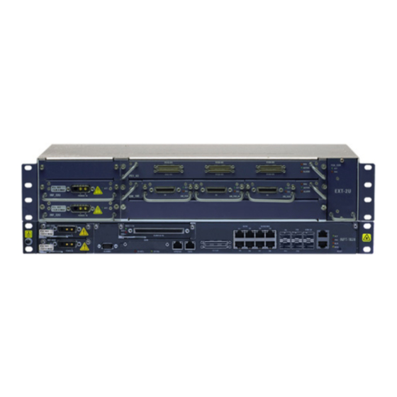
Eci Telecom NPT-1020 Installation And Maintenance Manual (216 pages)
Brand:
Eci Telecom
| Category:
Network Hardware
| Size: 12 MB
Table of Contents
Table of Contents
3
1 About this Manual
15
Document Organization
15
Intended Audience
15
Notes and Warnings
15
How to Obtain ECI Technical Documentation
16
Related Documentation
16
Technical Assistance
16
Figure 2-1: NPT-1020 Platform
18
EXT-2U Expansion Unit
19
2 Introduction
18
NPT-1020 Platform Layout
18
Figure 2-2: NPT-1020 Platform with Expansion Unit
19
Figure 2-3: EXT-2U Platform
19
Figure 2-4: EXT-2U Slot Layout
20
3 Before You Start
21
Overview
21
Outline of the Installation Procedure
21
Table 3-1: Typical NPT-1020 Equipment Installation Sequence
21
Table 3-2: Environmental Requirements
23
Power Sources
24
Site Preparation
23
Environmental Requirements
23
Physical Location
23
Table 3-3: Equipment Dimensions
24
Table 3-4: Recommended Coaxial Cable Assembly Tools
24
Figure 3-1: Typical Installation of Four NPT-1020 Platforms in an ETS
27
Preparing Cables and Fibers
27
Table 3-5: Traffic Cables Mating Connector Data for NPT-1020
30
Optical Fibers
31
Table 3-6: Traffic Cables Mating Connector Data for EXT-2U
31
Table 3-7: Optical Fibers and Mating Connector Data for NPT-1020
31
Grounding Requirements
32
Table 3-8: Optical Fibers and Mating Connector Data for EXT-2U
32
Work and Equipment Safety
32
DC Power Supply Requirements
33
AC Power Supply Requirements
34
Laser Safety Requirements
34
DC Power Cables
28
Grounding Cables
28
Alarm Cables
29
Management Cables
29
Timing (Clock) Cables
29
Electric Traffic Cables
30
TOD/1PPS Cable
30
Tools and Test Equipment
24
Cleaning Optical Connectors
25
Installing the NPT-1020 in Racks
25
Installation Plan
25
Integrating NPT-1020 Platforms and Other Equipment in One Rack
26
Typical NPT-1020 Installation
26
Table 3-9: NPT-1020 and EXT-2U Circuit Breaker Data
34
Table 3-10: NPT-1020 and EXT-2U Recommended Circuit Breakers
34
Figure 3-2: Laser Warning Label
35
Table 3-11: LC Transceivers Laser Information STM-4 SFP
36
Table 3-12: LC Transceivers Laser Information STM-1/100Basefx SFP
36
Figure 3-3: Basic ESD Warning Symbol
37
Table 3-13: LC Transceivers Laser Information Gbe SFP (OTGBE)
37
Personnel Training
38
Use of a Temporary EPA
38
Work Arrangements Within a Temporary EPA
39
Environmental and Health Concerns
40
Protection against Electrostatic Discharge
37
Figure 3-4: Pollution Control Logos
41
Figure 3-5: WEEE Recycling Symbol
41
4 Installing Equipment
42
Installation Sequence
42
Overview
42
Preliminary Preparations
42
Table 4-1: Outline of Typical NPT-1020 Equipment Installation Sequence
44
Unpacking and Performing Visual Inspection
44
Installation Options
45
Installing Ancillary Units in Racks
47
Installing the RAP-BG
47
Figure 4-3: Location of RAP-BG Grounding Stud
49
Figure 4-4: Identification of RAP-BG Cable Routes
49
Figure 4-5: Connecting DC Power Cables to the RAP-BG
50
Figure 4-6: RAP-BG Platform Power Cable Grounding Screws
51
Figure 4-7: RAP-BG Front Cover Removal
51
Figure 4-8: RAP-BG Circuit Breaker Installation
52
Figure 4-9: Platform DC Input Power Connector Pin Functions
52
Installing the RAP-4B
53
Figure 4-10: Locating RAP-4B Grounding Stud
54
Figure 4-11: RAP-4B with Grounding Cable
55
Figure 4-12: Identifying RAP-4B Cable Routes
55
Figure 4-13: Connecting DC Power Cables to the RAP-4B
56
Figure 4-14: RAP-4B Platform Power Cable Grounding Screws
57
Figure 4-15: RAP-4B Front Cover Removal
58
Figure 4-16: RAP-4B Circuit Breaker Installation
58
Figure 4-18: Threading Optical Fibers in the FST
60
Figure 4-19: Attaching Rack Mounting Brackets to the ODF
61
Figure 4-20: ODF Front Panel
61
Figure 4-21: ODF Open View
62
Figure 4-22: ODF Fiber Routes
62
Installing SM_10E/EM_10E Icps
63
Installing the Xddf-21 Patch Panel
63
Figure 4-23: Installing SM_10E/EM_10E Icps in the Rack
64
Installing the AC_CONV_UNIT
64
Figure 4-24: Installing the AC_CONV_UNIT in the Rack
65
Installing the NPT-1020 Shelf in the Rack
65
Installing the Rail Stiffeners
65
Attaching the NPT-1020 Shelf in the Rack
66
Grounding the NPT-1020 Shelf
66
Figure 4-25: Installing an INF-B1U in the NPT-1020
67
Installing Power Modules in the NPT-1020
67
Figure 4-26: Installing an INF-B1U-24V in the NPT-1020
68
Figure 4-27: Installing an INF-B1U-D in the NPT-1020
69
Figure 4-28: Installing an AC_PS-B1U in the NPT-1020
70
Installing Tslot Modules
70
Figure 4-29: Installing Tslot Modules in the NPT-1020
71
Installing SFP Modules
71
Figure 4-30: Installing an SFP in the NPT-1020
72
Installing the EXT-2U Platform in the Rack
72
Figure 4-31: Installing the H Connector in the NPT-1020
73
Installing the EXT-2U Shelf on the NPT-1020 Shelf
73
Installing the H Connector
73
Disassembling the EXT-2U from the NPT-1020
75
Figure 4-32: Removing the EXT-2U from the NPT-1020
75
Figure 4-33: Inserting the Thin Flat-Head Tool
75
Attaching the EXT-2U Shelf to the Rack
76
Figure 4-34: Raising the Rivet Cap
76
Figure 4-35: Removing the Rivet
76
Figure 4-36: EXT-2U Regular Slots Layout
77
Identifying Slots in the EXT-2U
77
Table 4-2: EXT-2U Modules
77
Figure 4-38: Installing an FCU_E2U in the EXT-2U
78
Installing an FCU_E2U in the EXT-2U
78
Installing Extension Cards in the EXT-2U
78
Figure 4-39: Installing an Extension Card in the EXT-2U
79
Figure 4-40: Installing a Power Module in the EXT-2U
80
Installing a Power Module in the EXT-2U
80
Installing Traffic Modules in the SM_10E/EM_10E
80
Connecting Fibers and Cables to the NPT-1020 Shelf
82
Connecting Power Cables to a DC Power Source
82
Connecting an AC Power Cable to the NPT-1020
83
Connecting Optical Fibers to Optical Modules
83
Routing and Connecting Electrical Interface Cables to the NPT-1020
84
Figure 4-42: PME1_63 Traffic Cable
86
Figure 4-43: PME1_63 Traffic Cable Installation
88
Routing and Connecting Data Interface Cables to Ethernet Interfaces
89
Routing and Connecting Electrical Cables for PCM Interfaces
90
Connecting the Timing (Clock) Cable
93
Connecting the TOD/1PPS Timing Cable
93
Figure 5-1: Wall-Mounted Cabinet General View
94
Installing the Interior Components
95
Installing the NPT-1020 in a Wall-Mounted Cabinet
95
Preparing the Rear Panel Holes
96
Installing the ODF
61
Figure 4-17: Platform DC Input Power Connector Pin Functions
59
Installing the FST
59
5 NPT-1020 Wall-Mounted Installations
94
Overview
94
Wall-Mounted Cabinet
94
Figure 5-2: Wall-Mounted Cabinet Interior Components
96
Figure 5-3: Preparing the Rear Panel Holes
97
Figure 5-4: Tools Required for Cabinet Installation
97
Figure 5-6: Installing the Support Rails
99
Figure 5-7: Installing the 19" Vertical Extrusions
99
Figure 5-8: Installing the C-Rail
100
Installing Cabling Accessories
100
Installing the C-Rail
100
Figure 5-9: Cabling Accessories Installed in the Cabinet
101
Installing Cable Guides
101
Figure 5-10: Cabling Accessories
102
Attaching Cable Clamping Bars
103
Attaching the Fiber Guide Tube
103
Installing Grounding Cables
103
Assembling the DDF
104
DDF 21 E1S Unit
104
Installing the 19" Vertical Extrusions
99
Figure 5-11: DDF General View
104
Figure 5-12: Installing the Brackets for ETSI Installation
105
Figure 5-13: Attaching the Connection Blocks
106
Figure 5-14: Installing an NPT-1020 Platform and Three Ddfs
107
Installing the NPT-1020 and Three Ddfs
107
Figure 5-15: Clip Nuts Distance in MM (NPT-1020 and Three Ddfs)
108
Installing Clip Nuts for the NPT and Ddfs
108
Installing the Ddfs
109
Installing the NPT-1020 Platform
109
Installing the NPT-1020, Two Ddfs, and an AC CONV Unit
109
Figure 5-16: Clip Nuts Distance in MM (NPT-1020, Two Ddfs, AC CONV Unit)
110
Connecting Cabinet Grounding
111
Installing Ddfs
111
Installing the AC CONV Unit
111
Installing the NPT-1020 Platform
111
Routing and Connecting Cables and Fibers in the Cabinet
112
Connecting Power Cables
113
Figure 5-17: Wall-Mounted Cabinet Cabling
113
Figure 5-18: Wall-Mounted Cabinet Cables Routing Front View
114
Connecting Alarm Cables
115
Figure 5-19: Wall-Mounted Cabinet Cables Routing Left Side View
115
Connecting Optical Fibers
116
Routing and Connecting Electrical Traffic Cables
116
Routing and Connecting Coaxial Cables
117
Connecting Fibers and Cables to the NPT-1020 in Wall-Mounted Cabinet
118
Connecting Management Cables
118
Connecting Timing (Clock) Cables
118
Figure 5-20: Installing Top and Bottom Covers
119
Installing the Top and Bottom Covers
119
Installing the Wall-Mounted Cabinet Covers and Door
119
Figure 5-21: Connecting Grounding Cables
120
Figure 5-22: Installing Side Covers
120
Installing the Side Covers
120
Figure 5-23: Connecting Grounding Cables
121
Figure 5-24: Installing the Front Door
121
Installing the Front Door
121
Figure 5-25: Connecting the Door Grounding Cable
122
Installing Cable Supports
122
Installing the Wall-Mounted Frame
122
Wall-Mounted Frame
122
Figure 5-26: Wall-Mounted Frame Installation
123
Attaching the Fiber Guide Tube
124
Figure 5-27: Attaching the Fiber Guide Tube
124
Preparing Installation Holes
124
Attaching the Wall-Mounted Frame
125
Installing the NPT-1020 and Accessories in the Wall-Mounted Frame
125
Figure 5-28: Installing a NPT-1020 and Three Ddfs
126
Installing the NPT-1020 and Three Ddfs (Option 1)
126
Installing the NPT-1020, a DDF, and a RAP-BG (Option 2)
127
Installing the NPT-1020, a DDF, and an AC/DC CONV (Option 4)
127
Installing the NPT-1020 and a DDF (Option 5)
128
Installing the Wall-Mounted Frame
128
Figure 5-29: Installing the Front Cover
129
Installing the Cover Holders
129
Attaching the Transparent Protection Cover
130
Connecting Wall-Mounted Frame Grounding
130
Figure 5-30: Routing and Connecting Cables and Fibers in the Wall-Mounted Frame
131
Routing and Connecting Cables and Fibers in the Frame
131
Connecting Power Cables
132
Figure 5-31: Wall-Mounted Frame Cable Routing - Left Side View
132
Connecting Alarm Cables
133
Connecting Optical Fibers
133
Routing and Connecting Coaxial Cables
134
Routing and Connecting Electrical Traffic Cables
134
Connecting Management Cables
135
Connecting Timing (Clock) Cables
135
Wiring the E1 Cables to the DDF
106
Figure 5-5: Installing the Rear Panel
98
Installing the Rear Panel
98
Attaching the Support Rails
99
6 Commissioning Tests
136
Site Commissioning Tests
136
Checking Cards and Modules Installed in each Shelf
136
Visual Inspection and Mechanical Checks
137
Test Equipment
136
Table 6-2: Visual Inspection and Mechanical Checks
137
Table 6-1: Card and Module Inventory
137
Table 6-4: 2 Mbps Tests
139
Table 6-5: 34 Mbps Tests
139
Network Timing Synchronization Test
140
Table 6-6: 45 Mbps Tests
140
Table 6-7: SDH Tests
140
Equipment Power-On Test
141
Input Sensitivity Test
141
Loss of Signal (LOS) Detection Test
141
Path Protection and Nonretrieval Test
142
Table 6-8: Traffic Stability Test Time Intervals
142
Traffic Stability Test
142
Severity Assignment Test
143
Transmission Alarm-Handling Test
143
Data Network Commissioning Tests
144
Maintenance Action Test
144
Throughput and Latency Tests
144
Frame Loss Rate Test
145
System Recovery and Reset Tests
145
Table 6-9: Throughput and Latency Test Results
145
Alarm-Handling Test
146
Stability Test
146
Table 6-10: Frame Loss Rate Test Results
146
Table 7-1: Preventive Maintenance Inspection and Checks
147
Onsite Troubleshooting
148
Troubleshooting Power Problems
149
Table 6-3: Measured Optical Levels
138
Platform Power-On Test Procedure
139
SDH Commissioning Tests
139
Test Equipment Setup
139
Measuring Optical Levels
138
7 Maintenance
147
Overview
147
Preventive Maintenance
147
Test Equipment, Tools, and Materials
147
Table 7-2: Troubleshooting Power Problems
149
Troubleshooting Using Component Indicators
150
Table 7-3: General Troubleshooting Procedures for NPT-1020 Power-On
151
Table 7-4: General Troubleshooting Procedures for NPT-1020
154
Table 7-5: General Troubleshooting Procedures for Optical Transceiver Plug-Ins
155
Table 7-8: General Troubleshooting Procedures for Extended Cards PE1_63/P345_3E
158
Table 7-7: Troubleshooting Procedures for SMD1B/SMS4 Cards
158
Figure 7-1: Inserting an SFP/CSFP/SFP+ Transceiver into a Module
164
Figure 8-2: AC Input Power Connector
165
Figure 8-1: POWER in Input Power Connector, Pin Functions
165
T3/T4 Timing Connector
166
Table 7-9: Special Troubleshooting Procedures for P345_3E Cards
159
Replacing Cards and Modules
160
Safety and Workmanship
160
Replacing Tslot Cards
161
Replacing Eslot Cards
162
Replacing Traffic Modules on the SM_10E/EM_10E
162
Replacing Icps for the SM_10E/EM_10E
163
Replacing Power Modules
163
Replacing SFP/CSFP/SFP+ Transceivers
164
8 Connection Data
165
AC_PS-B1U/AC_PS-E2U AC Input Power Connectors
165
INF-B1U/INF-B1U-D/INF-E2U DC Input Power Connectors
165
Overview
165
Table 8-1: T3/T4 Connector, PIN Identification
166
Figure 8-3: T3/T4 Connector, Pin Identification
166
1Pps/Tod Timing Connector
167
Alarms Connector
167
Figure 8-4: 1Pps/Tod Connector, Pin Identification
167
Table 8-2: 1Ppd/Tod Connector, PIN Identification
167
Table 8-3: Alarms Connector, Pin Assignment
168
Figure 8-5: Alarms Connector, Pin Identification
168
E1 Connectors on the PME1_21 and MSE1_16
174
Ethernet Interface Connectors
178
P345_3E Card Connection Data
179
PE1_63 Card Connection Data
179
PM345_3 Card Connection Data
179
SM_10E/EM_10E Card Connection Data
185
Connection Data for SM_EM_24W6E Interfaces
186
Connection Data for SM_V24E Interfaces
188
Connection Data for SM_V35_V11 Interfaces
191
Connection Data for SM_CODIR_4E Interfaces
193
ICP_VF Connection Data
196
ICP_V24 Connection Data
197
ICP_V35 Connection Data
199
ICP_V11_V24 Connection Data
200
ICP_DB37D Connection Data
202
RAP-4B Connectors
206
SHELF ALARM Connectors
206
ALARM IN/OUT Connector
207
Figure 8-17: RAP-4B ALARM IN/OUT Connector, Pin Identification
208
9 Rack Installation
211
Installing Equipment Racks
211
Marking Rack Floor
211
Installing the Rack on Concrete Floors
212
Installing the Rack on Wooden Floors
212
Figure 9-1: Mounting Diagrams for ETSI Racks
213
Figure 9-2: Mounting Diagrams for 19" and 23" Racks
214
Figure 9-3: Rack Mounting Diagram for Attachment to Suspended Overhead Tray
215
Grounding the Rack
215
Installing Extendable Rails
215
Installing the Rack on Suspended Overhead Trays
215
Figure 9-4: Example of an Approved European 19" Rack
216
Installing 19" Racks
216
Installing the Rack on Floating (Suspended) Floors
214
Advertisement
Advertisement
Related Products
Eci Telecom ONT B-FOCuS O-4F2PW
Eci Telecom ONT B-FOCuS O-4G2PW
Eci Telecom XDM-100
Eci Telecom Categories
Network Router
Network Hardware
IP Phone
Telephone
Fan
More Eci Telecom Manuals
Login
Sign In
OR
Sign in with Facebook
Sign in with Google
Upload manual
Upload from disk
Upload from URL