
Related Manuals for Eci Telecom XDM-100


Summary of Contents for Eci Telecom XDM-100
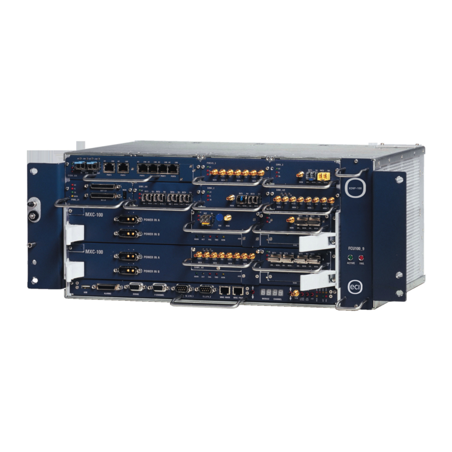
- Page 1 ® -100 Miniature MSPP for Metro-Access and Cellular Networks General Description=...
- Page 2 All trademarks mentioned herein are the property of their respective holders. ECI Telecom shall not be liable to you or to any other party for any loss or damage whatsoever or howsoever caused, arising directly or indirectly in connection with this documentation and/or disk, the information contained therein, its use or otherwise.
- Page 3 ® -100...
- Page 4 ® : XDM platforms are supplied in two versions, MPORTANT for SDH and SONET. The information contained in this document is applicable to both versions of the platforms...
-
Page 5: Table Of Contents
3.3.2 Multi-ADM and Multi-TM Modes ..........3-4 MXC Functionality ................3-5 Data Services ..................3-6 3.5.1 Benefits and Features............3-6 XDM-100 Traffic I/O Interface Modules ..........3-7 4. System Design ....................4-1 Control and Communication...............4-2 4.1.1 Internal Control and Processing ..........4-2 4.1.2 Communication with External Equipment and... - Page 6 6.5.1 Performance Management .............6-9 6.5.2 Alarm Management ..............6-10 6.5.3 Configuration and Inventory Management......6-10 6.5.4 Provisioning ................6-10 6.5.5 Security Management ............6-11 6.5.6 Interfaces and Management Transparency ......6-11 6.5.7 Auto-discovery ..............6-11 eCraft – An Advanced Web-based Craft Terminal ......6-12 ECI Telecom Ltd. Proprietary 417006-2005-013-A02...
- Page 7 Contents 7. Physical Description..................7-1 XDM-100 Shelf Configurations ............7-1 7.1.1 Basic XDM-100 Shelf..............7-1 7.1.2 Expanded XDM-100 Shelf with I/O Protection ......7-3 7.1.3 Nonredundant XDM-100 Shelf Layout ........7-5 Rack Installation .................7-6 Main Cross-Connect and Control (MXC) and External Connection Unit (ECU) Cards ............7-7 7.3.1 MXC Cards ................7-7...
- Page 8 Contents XDM® -100 ECI Telecom Ltd. Proprietary 417006-2005-013-A02...
- Page 9 Figure 6-1: ECI Telecom's layered architecture management concept ....6-1 Figure 6-2: eNM LightSoft main window ............... 6-4 Figure 6-3: XDM-100 shelf view as displayed in the EMS-XDM ......6-9 Figure 7-1: Basic XDM-100 shelf layout ............... 7-2 Figure 7-2: XDM-100 slot allocation..............7-3 Figure 7-3: Nonredundant XDM-100 shelf layout ..........
- Page 10 Contents XDM® -100 ECI Telecom Ltd. Proprietary 417006-2005-013-A02...
- Page 11 Table 7-2: I/O interface modules................7-9 Table 7-3: Aggregate interface modules............. 7-10 Table 8-1: I/O modules ..................8-6 Table 8-2: Mux/demux modules................8-7 Table 8-3: OADM modules ................... 8-7 Table 8-4: Splitter/Coupler modules ..............8-7 417006-2005-013-A02 ECI Telecom Ltd. Proprietary...
- Page 12 Contents XDM® -100 viii ECI Telecom Ltd. Proprietary 417006-2005-013-A02...
-
Page 13: Introduction
® In addition to the XDM -100 miniature Multiservice Provisioning Platform (MSPP) described in this document, ECI Telecom offers different types of XDM shelves, suitable for a variety of applications, topologies and configurations: ® -200 – a compact Coarse Wavelength Division Multiplexing ♦... -
Page 14: Xdm ® -100 - A Genuine Mspp In A Compact Package
ECI Telecom's XDM-100 miniature MSPP is the answer to all of these requirements – and more. -
Page 15: Features And Benefits
CWDM capability on the same single platform. This establishes a clear lead for metro-access applications with escalating bandwidth requirements. The XDM-100 is compact and resilient, making it perfectly suited for both ♦ indoor and outdoor enclosures. Due to its extended operating temperature range, it is also most suitable for harsh environmental conditions. - Page 16 Introduction XDM® -100 ECI Telecom Ltd. Proprietary 417006-2005-013-A02...
-
Page 17: Applications
This has brought about exceptional growth in the demand for more bandwidth at reduced costs. One of the XDM-100's key features is its Layer 2 Ethernet capabilities, which offer carriers a clear migration path from pure TDM-based, legacy services to new value-added data services. -
Page 18: Figure 2-1: Typical Ethernet Application
As many customers insist on a fully guaranteed QoS, the XDM-100 enables you to provide a range of QoS levels for different customers, as well as several service levels for the same customer, if required. -
Page 19: Metro-Access Applications
PDH/Async, SDH/SONET, Gigabit Ethernet (GbE), and Fast Ethernet services at local Points of Presence (POPs). The XDM-100 also provides a service layer, which terminates WAN links and consolidates Ethernet traffic arriving from the local access network. Traffic can be carried to local GbE interfaces or routed to the metro-core network. -
Page 20: Cellular Applications
♦ additional data services provided by cellular operators Functioning as both an ADM and a small cross-connect, the XDM-100 can easily convert from an aggregation component to a multi-ADM. This is performed once cellular operators decide to migrate from leased lines at the RAN to building their own infrastructure. - Page 21 The XDM-100 is designed to meet today’s growing network needs, such as the cost-reduction requirements needed in metropolitan and cellular applications. Optimized to meet the demands of today and tomorrow, the XDM-100 is the key building block for achieving highly competitive solutions. It enables operators to cater to unpredictable growth while avoiding the need to restructure their network.
- Page 22 Applications XDM® -100 ECI Telecom Ltd. Proprietary 417006-2005-013-A02...
-
Page 23: System Characteristics
Ethernet, and the QoS, scalability, and survivability of SDH/SONET. Used in many subnetwork topologies, the XDM-100 can handle a mixture of point-to-point, hubbed, and meshed traffic patterns. This combined functionality means operators can benefit from improved network efficiency and significant savings in terms of cost and footprint. -
Page 24: Metropolitan Transmission Networks
– the need for additional bandwidth to meet constantly increasing telecommunication requirements. Designed to meet the demands of metropolitan access markets, the XDM-100 is a reliable and scalable network platform that helps providers minimize initial investment and adjust their growth to future demands. -
Page 25: Tdm Configuration Options
It operates at the STM-1/4/16 or OC-3/12/48 line bitrates. To operate the XDM-100 as a TM, a single aggregate is required. To operate it as an ADM, two are used. Any service can then be provisioned by adding the relevant I/O modules. -
Page 26: Multi-Adm And Multi-Tm Modes
The multi-ADM configuration is ideal for hub sites that close several rings. When configured as a multi-TM, the XDM-100 replaces several TMs, terminating the SDH/SONET line and delivering lower-rate services to end-users. This configuration is suitable for dual or multiple homing applications. -
Page 27: Mxc Functionality
Figure 3-2: XDM-100 cross-connect scheme In the redundant configuration, MXC-A and MXC-B cards operate in parallel. Each XDM-100 matrix permits full nonblocking connectivity at all VC or STS levels. The matrices are connected to all I/O modules, providing 1.25 Gbps capacity to each of them. -
Page 28: Data Services
QoS demands. As a one-edge node platform, the XDM-100 supports data applications with Ethernet Layer 2 services via a special Ethernet module called the EIS-M (Ethernet Interface and Switching Module). -
Page 29: Xdm-100 Traffic I/O Interface Modules
♦ Data and other digital services ♦ The XDM-100 also supports a wide range of I/O interfaces and Ethernet Layer 2 services, enabling its deployment in transmission networks, as follows: SDH: E1, E3, DS-3, STM-1 electrical interface, STM-1 optical interface, ♦... - Page 30 System Characteristics XDM® -100 ECI Telecom Ltd. Proprietary 417006-2005-013-A02...
-
Page 31: System Design
Ethernet and SDH/SONET lines. Its modular architecture enables network operators to start small, and then simply and cost-effectively expand their systems to higher capacities as demand grows. This chapter describes the following XDM-100 component functions: Traffic and cross-connectivity, including: ♦... -
Page 32: Control And Communication
4.1.1 Internal Control and Processing The MXC card provides central control, alarm, maintenance, and communication functions for the XDM-100 network element. It also communicates with the control processors of the various cards using a master-slave control hierarchy. The MXC can be protected with an identical MXC card. A faulty MXC (control function) card does not affect traffic even if only a single card is installed. -
Page 33: Ne Software And Configuration Backup
The XDM-100's control subsystem is separate from the traffic subsystem. In case of a failure or extraction of the active MXC card, traffic is not impaired if an MXC protection card exists. -
Page 34: Timing And Synchronization
System Design XDM® -100 After the XDM-100 is switched on, a BIT program is automatically activated for both the initialization and normal operation phases. The operator can stop its execution (and also restart it) from eNM LightSoft™. BIT testing covers general tests, including module presence tests and periodic sanity checks of I/O module processors. -
Page 35: Figure 4-2: Timing Distribution Block Diagram
These outputs can be used to synchronize any peripheral equipment or switch. The operator can remotely manage network synchronization using the EMS-XDM, and can select and determine the priority of each XDM-100 timing source reference. These sources can include any external reference clock, PDH/Async line signal, SDH/SONET line signal or internal clock, as described previously. -
Page 36: Traffic And Cross-Connect Functionality
The link is fully redundant at intershelf levels. Figure 4-4 illustrates the simplified XDM-100 overall block diagram. It provides an overview of both the physical and functional partitioning of the system. ECI Telecom Ltd. Proprietary... -
Page 37: Figure 4-3: General Block Diagram
XDM® -100 System Design Figure 4-3: General block diagram 417006-2005-013-A02 ECI Telecom Ltd. Proprietary... -
Page 38: I/O And Data Traffic Functions
The XDM-100 supports PIM modules for different bitrates: 2 Mbps (E1), 34 Mbps (E3), 45 Mbps (DS-3), and 52 Mbps (STS-1). A PIM module occupies a single I/O slot in the XDM-100 shelf, providing all the functionality required to deploy a transport network, including Performance Monitoring (PM) for PDH/Async interfaces, 2 Mbps retiming (for PBAX synchronization), and 2 Mbps/45 Mbps frame for data applications. -
Page 39: Eis-M (Ethernet Interface And Switching Module)
♦ 4.4.3 EIS-M (Ethernet Interface and Switching Module) The EIS-M is used in the XDM-100 to provide Layer 2 Ethernet services. By simply plugging in the EIS-M, carriers are ready to roll out a new array of revenue-generating services. The EIS-M's Ethernet interfaces are connected to the end user’s Ethernet equipment. -
Page 40: Table 4-1: Eis-M Ports
Ethernet service. Each packet can be delivered through several EIS-Ms before arriving at its final destination. An XDM-100 shelf can accommodate up to four EIS-Ms, either working independently or protecting each other. There are three types of EIS-Ms with different types of ports, as described in the... -
Page 41: Overhead Unit (Ohu) Module
System Design 4.5 OverHead Unit (OHU) Module The XDM-100 OHU module provides orderwire functionality for field technicians, supporting conference calls between up to 10 participants. The OHU can be accommodated in any of the shelf’s I/O slots. In addition, the module supports: Interface overhead access bytes towards the MXC card ♦... -
Page 42: Power Feed
DC power source lines. The XDM-100 features a fully redundant power feed subsystem with two external power inputs available. A redundant xINF unit is located on each MXC card. The filter can be connected to both power inputs and distributes the -48 to -60 V DC battery plant inputs to all cards and modules via fully redundant power buses. -
Page 43: Tributary Protection Unit
The XDM-100 provides hardware protection to the electrical tributary modules with the Tributary Protection Unit (TPU). The TPU is an expansion shelf plugged on the top of the XDM-100. Connected to the control and power of the XDM-100 shelf, it becomes an integral part of the platform. - Page 44 System Design XDM® -100 4-14 ECI Telecom Ltd. Proprietary 417006-2005-013-A02...
-
Page 45: Protection And Redundancy
The system’s protection schemes comprise highly reliable trail protection arrangements, as well as equipment duplication on all units. The XDM-100 also provides protection for internal traffic paths. All traffic is fully redundant within the system and is routed via separate traffic paths and hardware units. -
Page 46: Dual Route Path Protection And Unidirectional Path Switched Ring (Upsr)
Path protection is supported by all aggregate and tributary I/O modules, and VC/STS trail protection may be selected from any two SIM/SAM interfaces. This flexibility enables the XDM-100 to integrate with other network nodes and provides end-to-end network path protection regardless of the network’s topology. This integrated path protection capability enables operators to smoothly integrate the XDM-100 into existing networks. -
Page 47: Figure 5-2: Path Diversity Protection Switching In A Mixed Equipment Ring
Route diversity protection ensures seamless protection integration and interoperability of XDM-100 systems with any other SDH/SONET equipment. Figure 5-1 shows a protection implementation when the XDM-100 is integrated with ECI Telecom's Optical Networks Division's XDM-1000, and Figure 5-2 shows another implementation with SYNCOM™ or third party SDH/SONET add/drop multiplexers. -
Page 48: Subnetwork Connection Protection (Sncp)
Protection and Redundancy XDM® -100 Dual route path protection also allows the XDM-100 to work in conjunction with other vendors’ SDH/SONET equipment at various transmission rates, regardless of topology and equipment (see Figure 5-3). Figure 5-3: Integration with other vendors’ SDH/SONET equipment 5.1.2 SubNetwork Connection Protection (SNCP) -
Page 49: Ethernet Protection/Rapid Spanning Tree Protocol (Rstp)
The XDM-100 supports MSP-L/APS in all optical or electrical SIM/SAM line modules (STM-1/OC-3, STM-4/OC-12, and STM-16/OC-48). MSP 1+1/APS 1+1 unidirectional and bidirectional modes are also supported. As in SNCP/UPSR and path protection, in the MSP/APS mode, the XDM-100 provides protection for both fiber and hardware faults. 417006-2005-013-A02... -
Page 50: Multiplex Section Shared Protection Ring (Ms-Spring) And Bidirectional Line Switched Ring (Blsr)
Protection and Redundancy XDM® -100 Figure 5-4 shows a four-fiber star XDM-100 with all links protected. This ensures uninterrupted service even in the case of a double fault. In this case, the system automatically performs MSP/APS switching within 50 ms. -
Page 51: Figure 5-5: Two-Fiber Ms-Sprring/Blsr Protection
In the example in Figure 5-5, if there is a fiber cut between sites A and D, traffic is transported through sites B and C on the black portion of the fiber that runs clockwise. Figure 5-5: Two-fiber MS-SPRring/BLSR protection 417006-2005-013-A02 ECI Telecom Ltd. Proprietary... -
Page 52: Table 5-1: Traffic Protection Schemes
Better service reliability SNCP (single and Mesh, ring, point-to-point ♦ Better reliability and network resilience as the dual node XDM-100 handles multiple failures over mesh interconnections) topologies Two-fiber Ring (within mesh topology) ♦ Better bandwidth utilization in case of uniform... -
Page 53: Management
Management 6.1 Layered Architecture ECI Telecom's Optical Networks Division's management concept is designed using layered architecture in accordance with applicable standards. Separate management layers make up this management structure. The lowest level, the Network Element Layer (NEL), constitutes the embedded agent software of the network elements. The... -
Page 54: Client/Server Architecture
6.3 Integration with Other Products The XDM has been designed to smoothly integrate its vast capabilities with networks that are not based on ECI Telecom products. This enables you to build real-world multivendor networks that ensure the free flow of management information between SDH/SONET and other complimentary access, radio, and switching products. -
Page 55: Management Interfaces
Both eNM LightSoft and the EMS-XDM user interfaces provide a powerful yet easy-to-use tool for managing your network. A single, user-friendly graphical interface combines configuration, maintenance, and performance management tools with fault handling, end-to-end trail definition, and fail-safe database backups for uninterrupted and reliable network operation. 417006-2005-013-A02 ECI Telecom Ltd. Proprietary... -
Page 56: Topology Management
Users move intuitively from an overall survey of the network landscape to detailed status and control views of any network element, transmission level, system card, or trail. ECI Telecom Ltd. Proprietary 417006-2005-013-A02... -
Page 57: Trail Configuration
For XDM NEs, eNM LightSoft supports both virtual and contiguous concatenation for the transport and cross-connection of VC-4/STS-3c signals. This is used for high-bitrate data services that require transport of payloads exceeding a single VC-4/STS-3c capacity. 417006-2005-013-A02 ECI Telecom Ltd. Proprietary... -
Page 58: Fault Management
LightSoft pre-filtered and sorted daily alarm logs. The eNM LightSoft fault management system is fully integrated and includes alarms for each NE, regardless of the layer being viewed (physical, SDH/SONET, or optical). ECI Telecom Ltd. Proprietary 417006-2005-013-A02... -
Page 59: Cut-Through
Should a failure occur in the active site, the operator can quickly switch over to the standby site and resume management of the network within minutes. The EMS-XDM database signature feature intelligently updates the standby site with all NE configuration data that has changed since the last replication. 417006-2005-013-A02 ECI Telecom Ltd. Proprietary... - Page 60 For system security, passwords, user action logs, and an optional keyboard lock feature are used to ensure system integrity. ECI Telecom Ltd. Proprietary 417006-2005-013-A02...
-
Page 61: Ems-Xdm
CORBA standard. The EMS-XDM may be co-located in the same platform, operate as a standalone, or be integrated under a non-ECI Telecom NMS or TMN umbrella system. The EMS-XDM can control scores of XDM NEs at a time and provides a wide range of XDM management functions, including alarms, configuration, inventory, provisioning, and security management (see Figure 6-3). -
Page 62: Alarm Management
A graphic display of the cross-connects makes editing easy. Simply point and click at cards and endpoints and then activate them. For additional ease of use, the cross-connection window is intuitive, and mass provisioning is possible on batch files. 6-10 ECI Telecom Ltd. Proprietary 417006-2005-013-A02... -
Page 63: Security Management
J0 byte. When activated, SIO-to-SIO or Optical Supervisory Channel (OSC) bidirectional links (in SDH/SONET networks) are automatically identified by the EMS-XDM and uploaded to the NMS layer via the MTNM interface. 417006-2005-013-A02 ECI Telecom Ltd. Proprietary 6-11... -
Page 64: Ecraft - An Advanced Web-Based Craft Terminal
The system provides the user with a clear view and control of NE internals – cards and objects, status, and configuration. Access from the eCraft is password-protected to ensure only authorized access to field-installed equipment. 6-12 ECI Telecom Ltd. Proprietary 417006-2005-013-A02... -
Page 65: Physical Description
7.1 XDM-100 Shelf Configurations 7.1.1 Basic XDM-100 Shelf The basic XDM-100 shelf is housed in a 231 mm deep, 443 mm wide, and 200 mm high equipment cage. The lower part of the shelf consists of the card cage and accommodates the MXC cards (main and protection) and the External Connection Unit (ECU). -
Page 66: Figure 7-1: Basic Xdm-100 Shelf Layout
Figure 7-1: Basic XDM-100 shelf layout The basic XDM-100 cage contains slots for I/O interface modules, and dedicated slots for the MXC cards and the ECU. The cage’s design and mechanical practice conform to international mechanical standards and specifications. -
Page 67: Expanded Xdm-100 Shelf With I/O Protection
Figure 7-2: XDM-100 slot allocation 7.1.2 Expanded XDM-100 Shelf with I/O Protection A TPU shelf can be mounted on top of the XDM-100 basic shelf to add protection of electrical I/O modules. The TPU is a single-shelf cage with slots for the Tributary Protection Modules (TPMs) and Tributary Control (TC) or Tributary Control and Fans (TCF) modules. -
Page 68: Table 7-1: Tpu Tributary Protection Modules
The TPMs provide protection to PIMs and electrical SIMs. Client traffic is connected directly to the TPM, and the TPM is connected by traffic cables to the XDM-100 main and protection modules. Power and control buses are connected to the TPM via the TPU backplane. -
Page 69: Nonredundant Xdm-100 Shelf Layout
DC voltages for the fans and the module circuits. 7.1.3 Nonredundant XDM-100 Shelf Layout The XDM-100 is also available in a nonredundant configuration. This shelf is equipped with only one MXC card. The second MXC position houses an MXC-BG card that bridges the buses of the second slot to the I/O modules. -
Page 70: Rack Installation
XDM® -100 7.2 Rack Installation The XDM-100 can be installed in either 2200 mm or 2600 mm ETSI racks, as well as in 19” and 23” racks. Figure 7-4 shows a typical installation of four shelves in a 2200 mm rack. -
Page 71: Main Cross-Connect And Control (Mxc) And External Connection Unit (Ecu) Cards
Physical Description 7.3 Main Cross-Connect and Control (MXC) and External Connection Unit (ECU) Cards The XDM-100 MXC and ECU cards were designed to facilitate simple installation and maintenance. They feature: Electrical interface connectors that are integrated into the I/O modules, ♦... -
Page 72: Ecu Cards
MXC card. This card also provides the physical connections for these interfaces. Two types of ECU cards are available for the XDM-100: ECU-F and ECU (reduced cost). The ECU-F supports the following management and alarm interfaces and functions: ®... -
Page 73: I/O And Aggregate Modules
7.4 I/O and Aggregate Modules 7.4.1 I/O Modules Eight slots are available in the XDM-100 shelf to accommodate the various types of I/O modules. Each type of module (PIM, SIM, or EIS_M) can be inserted in any of the I1 through I8 positions without limitation (the EIS_M occupies two slots). -
Page 74: Aggregate Modules
SAM are connected to both MXC cards. A variety of aggregate modules with electrical, optical and mixed interfaces, and at bitrates from STM-1 to STM-16/OC-3 to OC-48 are available. Table 7-3 details the XDM-100 aggregate module data configuration. Table 7-3: Aggregate interface modules Module... -
Page 75: Xdm ® -100H
The XDM-100H provides a clear lead for metro-access applications, taking full advantage of a varied infrastructure network, with vision toward expanding bandwidth requirements, at an unbeatably low price. This crossbreed option retains all the modularity of the original XDM-100 shelf. ® : The XDM -100H is a cost option and can only be implemented if your XDM-100 is licensed appropriately. -
Page 76: Protection
Due to the high capacity of traffic transmitted through CWDM systems, protection is of utmost importance. The XDM-100H incorporates two types of optical protection schemes: Optical Channel (OCH) 1+1 protection ♦ Optical Multiplex Section Protection (OMSP) for line protection ♦ ECI Telecom Ltd. Proprietary 417006-2005-013-A02... -
Page 77: Figure 8-2: Och Protection Scheme
The protected channels are user- selected. Figure 8-2: OCH protection scheme 417006-2005-013-A02 ECI Telecom Ltd. Proprietary... -
Page 78: Figure 8-3: Omsp Line Protection
This is a low cost, hardware-based implementation with a very small footprint. Switch-to- protection time is less than 5 ms. Figure 8-3: OMSP line protection ECI Telecom Ltd. Proprietary 417006-2005-013-A02... -
Page 79: Physical Description
Tributary Protection Unit/Optical CWDM Unit (TPU/OCU), mounted on top ♦ of the main XDM-100 shelf, with four slots (for supporting any mix of mux/demux, splitter/coupler, OADM, or TPM modules), and a Tributary Control (TC) module for carrying the power and control from the main shelf to the TPU/OCU backplane. -
Page 80: Tributary Protection Unit/Optical Cwdm Unit (Tpu/Ocu)
(TPU/OCU) TPU/OCU shelf layout The TPU/OCU shelf is installed on top of the main XDM-100 shelf and supports tributary protection, mux/demux, CWDM, OADM, splitter/coupler, and modules. The shelf connects to a connector on top of the main XDM-100 shelf, which provides the power and control buses required for its operation. -
Page 81: Table 8-2: Mux/Demux Modules
4 splitters and 4 couplers for optical protection for 850 nm, 50 µm, MM fiber MO_4CP4SMM62 4 splitters and 4 couplers for optical protection for 850 nm, 62.5 µm, MM fiber MO_4CP4SPSM 4 splitters and 4 couplers for optical protection for 1310/1550 nm, SM fiber 417006-2005-013-A02 ECI Telecom Ltd. Proprietary... - Page 82 XDM®-100H XDM® -100 ECI Telecom Ltd. Proprietary 417006-2005-013-A02...
-
Page 83: Reference Documents
11. ETSI ETS 300 462 (Parts 1, 2, 3, 4, 5) – Transmission and Multiplexing (TM) – Generic Requirements for Synchronization Networks; Synchronization Network Architecture; The Control of Jitter and Wander within Synchronization; Timing Characteristics of Slave Clocks Suitable for Operation in Synchronous Digital Hierarchy (SDH) Equipment. 417006-2005-013-A02 ECI Telecom Ltd. Proprietary... - Page 84 26. GR-63-CORE – Network Equipment Building System (NEBS) Requirements: Physical Protection. 27. IEC 917 – Modular Order for the Development of Mechanical Structures for Electronic Equipment Practices. 28. IEC/UL 60950 – Safety of Information Technology Equipment. ECI Telecom Ltd. Proprietary 417006-2005-013-A02...
- Page 85 42. ITU-T Recommendation G.681 – Functional Characteristics of Interoffice and Long-haul Line Systems Using Optical Amplifiers, Including Optical Multiplexing. 43. ITU-T Recommendation G.691 – Optical Interfaces for Single Channel SDH Systems with Optical Amplifiers and STM-64 systems (Draft). 417006-2005-013-A02 ECI Telecom Ltd. Proprietary...
- Page 86 57. ITU-T Recommendation G.811 – Timing Characteristics of Primary Reference Clocks. 58. ITU-T Recommendation G.812 – Timing Requirements of Slave Clocks Suitable for Use as Node Clocks in Synchronization Networks. 59. ITU-T Recommendation G.813 – Timing Characteristics of SDH Equipment Slave Clocks (SEC). ECI Telecom Ltd. Proprietary 417006-2005-013-A02...
- Page 87 75. RFC-1493 – Definition of Managed Objects for Bridges. 76. RFC-1662 – PPP in HDLC-life Framing. 77. RFC-1757 – Remote Network Monitoring Management Information Base. 78. RFC-2108 – Definitions of Managed Objects for IEEE 802.3 Repeater Devices using SMIv2. 417006-2005-013-A02 ECI Telecom Ltd. Proprietary...
- Page 88 Reference Documents XDM®-100 79. RFC-2615 – PPP over SONET/SDH. 80. RFC-2737 – Entity MIB (Version 2). 81. RFC-2823 – PPP over Simple Data Link (SDL) using SONET/SDH with ATM-like Framing. ECI Telecom Ltd. Proprietary 417006-2005-013-A02...
-
Page 89: Glossary
Base Station Transceiver Subsystem CAPEX CAPital EXpenditure Communication Control Panel Customer Located Equipment Central Office CORBA Common Object Request Broker Architecture Customer Premises Equipment Consolidation Unit Digital Communications Channel Data Communication Network XDM Data I/O card 417006-2005-013-A02 ECI Telecom Ltd. Proprietary... - Page 90 Desktop or laptop PC-based craft terminal EIS-M Ethernet Interface and Switching Module ElectroMagnetic Compatibility Element Management Layer Element Management System ECI Telecom Ltd.'s Network Manager eNM-XDM XDM element management system Engineering OrderWire ETSI European Telecommunication Standards Institute Fast Ethernet 100BaseT.
- Page 91 Optical Add/Drop Multiplexer OverHead Access OPEX OPerational EXpenditure Optical Supervisory Channel OSNR Optical Signal-to-Noise Ratio Orderwire channel Plesiochronous Digital Hierarchy PDH I/O Module PDH Input/Output Performance Monitoring Point of Presence Quality of Service Remote Access Network 417006-2005-013-A02 ECI Telecom Ltd. Proprietary...
- Page 92 Tributary Control and Fans Time Division Multiplexing Terminal Multiplexer TeleManagement Forum Telecommunications Management Network TiMing Unit Tributary Protection Module Tributary Protection Unit TVCXO Temperature Compensated Voltage Controlled Crystal Oscillator Unavailable Seconds UPSR Unidirectional Path Switched Ring ECI Telecom Ltd. Proprietary 417006-2005-013-A02...
- Page 93 XDM® -100 Glossary Universal Serial Bus Virtual Container Virtual Private Network Wide Area Network 417006-2005-013-A02 ECI Telecom Ltd. Proprietary...
- Page 94 Glossary XDM® -100 ECI Telecom Ltd. Proprietary 417006-2005-013-A02...
-
Page 95: Index
4-2 interfaces and management transparency, NE software and configuration backup, 4-3 6-11 Cut-through process, eNM LightSoft, 6-7 performance management, 6-9 CWDM, 1-1, 1-3, 3-1, 4-9, 8-1, 8-2, 8-4, 8-5, provisioning, 6-10 security management, 6-11 417006-2005-013-A02 ECI Telecom Ltd. Proprietary... - Page 96 Metro-Access Applications QoS, 2-1, 2-2, 3-1, 3-6, 6-9 Quality of Service. See QoS multirings, 2-2 point-to-point topologies, 2-2 STM-1/4/16 aggregation, 2-2 Rack Installation, 7-6 Metropolitan Transmission Networks, 3-2 Modular Architecture, 3-2 SAM (SDH Aggregate) Modules, 4-8 ECI Telecom Ltd. Proprietary 417006-2005-013-A02...
- Page 97 -2000, 1-1 MXC functionality, 3-4 ® -400, 1-1 TDM configuration options, 3-3 ® -500, 1-1 XDM-100 traffic I/O interface modules, XDM-100 cellular applications, 2-3 System Design, 4-1 client/server architecture, 6-2 control and communication, 4-2 data applications, 2-1 I/O and data traffic functions, 4-8...
- Page 98 Index XDM® -100 ECI Telecom Ltd. Proprietary 417006-2005-013-A02...
Need help?
Do you have a question about the XDM-100 and is the answer not in the manual?
Questions and answers