Table of Contents
Advertisement
Quick Links
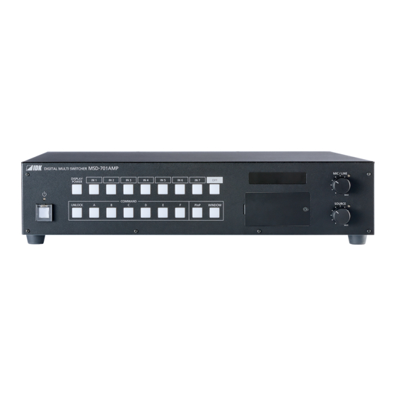
Digital Multi Switcher with Integrated Audio Power Amplifier
Thank you for choosing our product.
To ensure the best performance of this product, please read this user guide fully and carefully before
using it and keep this manual together with the product for future reference as needed.
IDK Corporation
MSD-701AMP
<User Guide>
Ver.1.1.0
Advertisement
Table of Contents

Related Manuals for IDK MSD-701AMP


Summary of Contents for IDK MSD-701AMP
- Page 1 Digital Multi Switcher with Integrated Audio Power Amplifier MSD-701AMP <User Guide> Ver.1.1.0 Thank you for choosing our product. To ensure the best performance of this product, please read this user guide fully and carefully before using it and keep this manual together with the product for future reference as needed.
- Page 2 Windows is either registered trademark or trademark of the Microsoft Corporation in the United States and other countries. The terms Anti-snow and Connection Reset are registered trademarks of IDK Corporation in Japan. All other company and product names mentioned in this manual are either registered trademarks or...
- Page 3 Some information contained in this User guide such as exact product appearance, diagrams, menu operations, and so on may differ depending on the product version. This User guide is subject to change without notice. You can download the latest version from IDK’s website at: http: //www.idkav.com...
- Page 4 MSD-701AMP User Guide Safety Instructions Read and understand all safety and operating instructions before using this product. Follow all instructions and heed all warnings/cautions. Enforcement Symbol Description Indicates the presence of a hazard that may result in death or serious...
- Page 5 ● Do not repair, modify or disassemble. Since the product includes circuitry that uses potentially lethal, high voltage levels, disassembly by unauthorized personnel may lead to the risk of fire or electric shock. For internal inspection or repair, contact your IDK Do not representative.
- Page 6 Unplug If you continue to use the product under these conditions, it may increase the risk of electrical shock or fire. For maintenance and repair, contact your IDK representative. ● Unplug immediately if water or other objects are directed inside.
- Page 7 MSD-701AMP User Guide Caution ■ For installing and connecting products: ● Do not place the product in a location where it will be subjected to high temperatures. If the product is subjected to direct sunlight or high temperatures while under operation, it may affect the product’s performance and reliability and may increase the risk of fire.
-
Page 8: Table Of Contents
MSD-701AMP User Guide Table of Contents 1 Included items ............................... 13 2 About MSD-701AMP ............................ 14 3 Features ................................ 15 4 Panels ................................16 4.1 Front/Side panels ........................... 16 4.2 Rear panel .............................. 18 5 System Configuration Example ........................20 6 Installation .............................. - Page 9 MSD-701AMP User Guide 8.4.6 Automatic reload ..........................54 8.4.7 Saving/Restoring settings ........................ 54 8.4.8 Initialization ............................56 9 Configuration and Control ..........................57 9.1 Menu ..............................57 9.1.1 Normal setting menu ........................57 9.1.2 Advanced setting menu ........................59 9.2 Input signal automatic detection ......................63 9.3 Channel switching mode ........................
- Page 10 MSD-701AMP User Guide 9.7.9 Automatic detection of video input interruption ................89 9.7.10 Fixing settings for each input signal ....................90 9.8 Input timing ............................. 91 9.8.1 Automatic measurement ......................... 93 9.8.2 The total number of horizontal pixels ....................95 9.8.3 Horizontal start position ........................
- Page 11 MSD-701AMP User Guide 9.12.3 Audio input reference level ......................117 9.12.4 Compressor ..........................117 9.12.5 Equalizer ............................119 9.12.6 Input Lip Sync ..........................119 9.12.7 MIC/LINE volume knob ....................... 120 9.13 EDID ..............................121 9.13.1 EDID selection ..........................122 9.13.2 Input resolution ..........................122 9.13.3 Copying EDID ..........................
- Page 12 MSD-701AMP User Guide 9.19 Bitmap ..............................153 9.19.1 Bitmap image output ........................154 9.19.2 Background color ........................154 9.19.3 Aspect ratio..........................155 9.19.4 Image position ..........................155 9.19.5 Assigning input channel ......................156 9.19.6 Start-up bitmap output ......................... 156 9.19.7 Dividing memory area ......................... 156 9.19.8 Input image capture ........................
-
Page 13: Included Items
MSD-701AMP User Guide 1 Included items Ensure that all items illustrated below are included in the package. If any items are missing or damaged, please contact IDK. One (1) main unit (MSD-701AMP) One (1) 8-pin captive screw Two (2) 6-pin captive screw... -
Page 14: About Msd-701Amp
The MSD-701AMP can be configured remotely from RS-232C and LAN. External devices can be controlled via RS-232C, LAN, CEC, or contact closure by registering control commands. -
Page 15: Features
・ HDBaseT: RS-232C, LAN and CEC are supported ・ Standby button For long reach mode, video signals up to 1080p (24 bit) can be transmitted to 492 ft. (150 m) at maximum if using with IDK's HDBaseT products supporting 328 ft. (100 m) transmission. -
Page 16: Panels
MSD-701AMP User Guide 4 Panels 4.1 Front/Side panels ● Front panel ② ⑫ ⑯ ⑧ ⑦ ⑥ ⑨ ③ ① ⑪ ⑩ ④ ⑤ ⑭ ⑬ ⑮ ● Side panels ⑰ ⑰ [Fig. 4.1] Front/side panel drawings... - Page 17 MSD-701AMP User Guide [Table 4.1] Front/side panel features Feature Description Standby button Powers on the MSD or sets the MSD to Standby state. ① Works when Main power switch (POWER) is powered on. Power indicator Shows power status. ② Lights green : Powered on...
-
Page 18: Rear Panel
MSD-701AMP User Guide 4.2 Rear panel ⑦ ⑪ ⑬ ⑭ ⑲ ⑧ ⑥ ⑮ ⑯ ⑰ ① ③ ⑨ ⑩ ⑱ ③ ② ⑫ ④ ⑤ [Fig. 4.2] Rear panel drawings [Table 4.2] Rear panel features [1/2] Feature Description Main power switch Controls the main power. - Page 19 MSD-701AMP User Guide [2/2] Feature Description LINE input connector Input connector for line audio ⑧ Connect audio mixer, CD player, or the like. Connector type is 5-pin captive screw connector. HDMI output connectors Output connectors for HDMI and DVI signals, interfaces sink devices ⑨...
-
Page 20: System Configuration Example
Up to 492 ft. (150 m) : 1080p (24 bit) in Long reach mode For long reach mode, video signals up to 1080p (24 bit) can be transmitted to 492 ft. (150 m) at maximum if using with IDK’s HDBaseT products supporting 328 ft. (100 m) transmission. [Fig. 5.1] System configuration example... -
Page 21: Installation
MSD-701AMP User Guide 6 Installation 6.1 Precautions When installing the MSD, observe the following precautions; otherwise, the internal temperature increases and it may affect the product lifetime and operation. ・ Do not stack or place one MSD directly on top of another MSD. -
Page 22: Connection Details
MSD-701AMP User Guide 7 Connection Details 7.1 Precautions When connecting the MSD to external devices, observe the following precautions. ・ Read manuals for the external devices. ・ Before connecting cables to the MSD or an external device, dissipate static electricity by touching grounded metal such as equipment racks before handling signal cables. -
Page 23: Securing Hdmi Cable
With long reach mode, video signals up to 1080p (24 bit) can be transmitted to 492 ft. (150 m) at maximum if using with IDK's HDBaseT products supporting 328 ft. (100 m) transmission. PoH enables DC power transmission to HDBaseT supported transmitters. -
Page 24: Category Cable
MSD-701AMP User Guide 7.2.3 Category cable To ensure the best performance with category cables, select a high quality category cable type, ensuring that proper pinning and pairing requirements are observed. ・ Cat5e UTP/STP and Cat6 UTP/STP can be used, but we recommend CAT.5E HDC cable* for optimal performance. -
Page 25: Dvi-I Input Connector
MSD-701AMP User Guide Note: If there is a problem in the transmission path, video or audio may be interrupted. Check the “[Table 7.1]” above. If the problem persists, it may be necessary to shorten the category cable. 7.2.4 DVI-I input connector Female DVI-I (29-pin) connectors are used for DVI inputs. -
Page 26: Connecting Audio Device
MSD-701AMP User Guide 7.3 Connecting audio device The MSD can be connected to the following audio devices: Source device : Blu-ray disc players, DVD players, wireless mic Receivers and the like. Sink devices : Speakers, recorder, and the like. High-impedance speakers can be connected to the SPEAKER 2 connector. -
Page 27: Audio/Line
MSD-701AMP User Guide 7.3.1 Audio/Line Connect the supplied 5-pin captive screw connector to the MSD. The MSD supports both balanced and unbalanced signals. 28 AWG to 16 AWG conductor gauge and a strip length of 0.28 in. (7 mm) are recommended. -
Page 28: Speaker
MSD-701AMP User Guide 7.3.3 Speaker ■ SPEAKER1 connector can be used for a 4 Ω to 16 Ω speaker Connect the supplied 4-pin captive screw connector (5.08 mm) to the MSD. 24 AWG to 12 AWG conductor gauge and a strip length of 0.28 in. (7 mm) are recommended. -
Page 29: Connecting Control Devices
MSD-701AMP User Guide 7.4 Connecting control devices The MSD can control devices that are connected to HDBaseT connectors can also be controlled via RS-232C or LAN. Screen Button switch Controller Power distributor Contact output HDMI Contact remote HDBaseT HDBaseT RS-232C... -
Page 30: Rs-232C Communication
MSD-701AMP User Guide 7.4.1 RS-232C communication The RS-232C connector, HDBaseT input connector, and HDBaseT output connector can communicate with control devices (communication commands) and external devices (control commands) over RS-232C communication. You can select TRANCEIVER mode or TRANSMITTER mode for each connector in “9.14.2 RS-232C operation mode”. -
Page 31: Lan Communication
MSD-701AMP User Guide 7.4.2 LAN communication The internal switching hub enables connections between the MSD’s LAN connector and LAN connectors of twisted pair cable transmitters and receivers that are connected to HDBaseT I/O connectors. Bidirectional communication is also available. Communication control command from PC to the MSD and control command output from the MSD to external devices can be executed from all LAN ports. -
Page 32: Remote Connector
MSD-701AMP User Guide 7.4.3 REMOTE connector The MSD includes two inputs for controlling MSD’s power status and one contact output for controlling external power distribution unit. Connect the supplied 8-pin captive screw connector to the MSD. 28 AWG to 16 AWG conductor gauge and a strip length of 0.28 in. (7 mm) are recommended. -
Page 33: Contact Closure
MSD-701AMP User Guide 7.4.4 Contact closure The MSD has a total of six independently controlled contact closure channels for external control. Each connector supports three channels. The maximum load is 1 A at 24 VDC per contact. Connect a cable to the 6-pin captive screw connector, and then insert into the appropriate connector on the MSD. -
Page 34: Operation
MSD-701AMP User Guide 8 Operation The following figures show how video and audio signals are converted and transmitted. IN 1 HDMI IN 2 HDMI IN 3 HDMI Scan converter IN 4 HDMI OUT A HDMI IN 5 HDMI Video OUT B... - Page 35 MSD-701AMP User Guide [Fig. 8.2] Audio signal transmission...
-
Page 36: Powering On/Off
MSD-701AMP User Guide 8.1 Powering on/off Turn on the “POWER” switch of the rear panel to power on or the MSD or change to standby state. Use the “Standby” button to switch standby state and powered on state. [Table 8.1] Power status... -
Page 37: Front Panel Operations
MSD-701AMP User Guide 8.3 Front panel operations 8.3.1 Selecting menu To select menu: 1. Remove the cover from the front panel. M3 screws Cover [Fig. 8.3] Removing cover 2. Press the “MENU/ENTER” button. 3. Select the desired menu using “arrow” buttons. -
Page 38: Selecting Input Channels
MSD-701AMP User Guide Notes: ・ The MSD menu consists of setting menus and advanced setting menus. 【See: 9.1 Menu】 ・ To avoid losing settings, do not interrupt power to the MSD while “NOW SAVING” is displayed; otherwise, the setting information may be lost. -
Page 39: Controlling Mic/Line Volume
MSD-701AMP User Guide 8.3.4 Controlling mic/line volume Rotate the “MIC/LINE” knob clockwise to increase the level or anticlockwise to decrease the volume. The front display shows the set volume level (dB). The MIC/LINE knob setting can be assigned to mic or line separately. -
Page 40: Controlling Source Audio Volume
MSD-701AMP User Guide 8.3.5 Controlling source audio volume Rotate the “SOURCE” knob clockwise to increase the level or anticlockwise to decrease the volume. The front display shows the set volume level (dB). 【See: 9.11 Output audio】 The SOURCE LED shows status of SPEAKERs. -
Page 41: Enabling Window Combination
MSD-701AMP User Guide 8.3.6 Enabling window combination PinP Side-by-side [Fig. 8.9] Pattern 1 and Pattern 5 To set window combination: 1. Select a layout pattern from 6 patterns below using the “PinP” button. Subwindow Main window ① ② ③ PinP disabled... - Page 42 MSD-701AMP User Guide 2. Assign a video using the “WINDOW” button and input channel selection buttons. “WINDOW” button does not light : Main window will be switched. “WINDOW” button light green : Subwindow will be switched. IN6 video is output.
- Page 43 MSD-701AMP User Guide 4. Set the following items as needed. [Table 8.3] Settable menus for video combination Applied for each Applied to all Menu Description pattern separately pattern Output position, size, Aspect ratio for sink device ✓ and masking Image position ✓...
-
Page 44: Registering/Executing Control Commands
MSD-701AMP User Guide 8.3.7 Registering/Executing control commands External devices that are connected to the MSD can be controlled by registering commands to the following buttons: ・ “Standby” button ・ “Input channel selection” button ・ “COMMAND” buttons ・ “DISPLAY POWER” button No control commands are registered by default. -
Page 45: Recalling Crosspoint
MSD-701AMP User Guide 8.3.8 Recalling crosspoint Up to nine crosspoint can be saved to crosspoint. 【See: 9.18 Preset memory】 Crosspoint memories No.1 to 6 (COMMAND “A” to “F”) are linked to “COMMAND” buttons. To recall crosspoint: 1. Press the “UNLOCK” button. The “UNLOCK” button light red. -
Page 46: Front Panel Security Lockout
MSD-701AMP User Guide 8.3.9 Front panel security lockout The front panel security lockout limits operation of the MSD from the front panel to prevent accidental changes to the controller settings. 【See: 9.21.1 Grouping front panel security lockout 】 【See: 9.20.4 Front panel security lockout 】... -
Page 47: Initialization
MSD-701AMP User Guide 8.3.10 Initialization All user configurable settings can be reset to their respective factory default values by powering the MSD on while simultaneously depressing the “BACK” button. Press and hold the “BACK” button until you hear a long beep tone. -
Page 48: Web Browser Operations
MSD-701AMP User Guide 8.4 WEB browser operations The MSD can be controlled, monitored, or configures remotely also via WEB browser. 8.4.1 Starting WEB menu To control the MSD from a WEB browser, enter the IP address that is programmed into the MSD in the address bar of the WEB browser. -
Page 49: Form Controls
MSD-701AMP User Guide 8.4.2 Form controls To set values from WEB menu: 1. Select the desired item from the menu to display setting items in the submenu. 2. If there is a setting item that can be set for each channel, channel tab will be displayed. -
Page 50: Normal/Advanced Menu
MSD-701AMP User Guide 8.4.3 Normal/Advanced menu The MSD menus consist of normal setting menus and advanced setting menus. To set advanced setting menus: 1. Select [SYSTEM SETTINGS] from [MENU]. 2. Set [ADVANCED MENU] to [ON]. It is set to [OFF] by default. -
Page 51: Editing Crosspoint Name
MSD-701AMP User Guide 8.4.4 Editing crosspoint name To edit crosspoint name: 1. Click the [NAME EDIT] button from [CROSS POINT] to open the [NAME EDIT] window. 2. Enter up to 10 one-byte characters. You can edit the following names Input channel name... -
Page 52: Registering Bitmap
MSD-701AMP User Guide 8.4.5 Registering bitmap To register output video to bitmap memory: 1. Select [SYSTEM SETTINGS] from [MENU]. 2. Set [ADVANCED MENU] to [ON]. 3. Select [BITMAP] > [MAIN]. 4. Set [FREEZE] to [ON] to freeze the output video temporarily. - Page 53 MSD-701AMP User Guide To register bitmap file to bitmap memory: 1. Select [SYSTEM SETTINGS] from [MENU]. 2. Set [ADVANCED MENU] to [ON]. 3. Select [BITMAP] > [MAIN]. 4. Select the desired bitmap file from [FILE]. 5. Click [SEND] to register the bitmap file to bitmap memory.
-
Page 54: Automatic Reload
MSD-701AMP User Guide 8.4.6 Automatic reload To set automatic reload interval of [CROSS POINT] and [VIEW STATUS] windows: 1. Select [SYSTEM SETTINGS] from [MENU]. 2. Select the desired interval in 1-second increments (1 to 10 seconds) for [AUTO RELOAD TIME]. - Page 55 MSD-701AMP User Guide To restore settings from PC: 1. Select [SYSTEM SETTINGS] from [MENU]. 2. Select a file from [Choose File]. 3. Click the [RESTORE] button of [BACKUP/RESTORE]. Do not perform other WEB operations or power off the MSD during the operation.
-
Page 56: Initialization
MSD-701AMP User Guide 8.4.8 Initialization To reset the MSD to factory defaults: 1. Select [SYSTEM SETTINGS] from [MENU]. 2. For initializing settings except RS-232C and LAN communication settings: Click the [NORMAL INITIALIZE] button. For initializing all settings including the communication settings: Click the [ALL INITIALIZE] button. -
Page 57: Configuration And Control
MSD-701AMP User Guide 9 Configuration and Control 9.1 Menu The MSD menus consist of normal setting menus and advanced setting menus. You can switch setting menu/advanced menu, using the “MENU/ENTER” button (“Top” → “SYSTEM SETTINGS” → “ADVANCED MENU”). 【8.4.3 Normal/Advanced menu】... - Page 58 MSD-701AMP User Guide │ │ │ ├─SPEAKER2 MIXING ├─USER PRESET P.148 │ │ (SPEAKER 2 output mixing) │ │(Preset memory) │ ├─SPEAKER OUT │ ├─RECALL CROSSPOINT │ │ (SPEAKER 2 output) │ │ (Recalling crosspoint) │ └─TEST TONE │ ├─STORE CROSSPOINT (Test tone) │...
-
Page 59: Advanced Setting Menu
MSD-701AMP User Guide 9.1.2 Advanced setting menu MSD-701AMP │ │ ├─SWITCHING MODE P.64 │ ├─EDID ERR. OUTPUT MODE │ (Channel switching mode) │ │ (Sink device EDID check) │ └─CEC CONNECTION │ ├─OUTPUT IMAGE P. 64 (CEC connection) │ │ │(Output position, size, and masking) │... - Page 60 MSD-701AMP User Guide │ │ ├─INPUT TIMING P.91 │ ├─INPUT HUE │ │(Input timing) │ │ (Input hue) │ ├─ANALOG MEASUREMENT │ ├─INPUT SATURATION │ │ (Automatic measurement) │ │ (Input saturation) │ ├─H TOTAL PIXELS │ ├─INPUT BLACK LEVEL │...
- Page 61 MSD-701AMP User Guide │ │ ├─EDID SETTINGS P.121 ├─CONTROL COMMAND P.133 │ │(Control command) │ │(EDID) │ ├─EDID SELECTION │ ├─COMMAND REGISTER/EDIT │ │ (EDID selection) │ │ (Registering/Editing control command) │ ├─REPLY REGISTER/EDIT │ ├─RESOLUTION │ │ (Input resolution) │...
- Page 62 MSD-701AMP User Guide │ │ ├─DIVIDE MEMORY │ │ (Dividing memory area) │ └─CAPTURE VIDEO (Input image capture) │ │ ├─POWER ON SETTINGS P.160 │ │(Startup) │ ├─START-UP MODE │ │ (Power state) │ ├─DISPLAY POWER CMD. EXE. │ │ (Command execution for DISPLAY POWER button) │...
-
Page 63: Input Signal Automatic Detection
MSD-701AMP User Guide 9.2 Input signal automatic detection The MSD continuously monitors its input signals. If a particular signal has previously been connected to the MSD’s input, the output signal will be presented in the same format as it was during the most recent session. -
Page 64: Channel Switching Mode
MSD-701AMP User Guide The following attributes are saved for each input signal. [Table 9.1] Attributes saved for each input signal 9.4 Output position, size, and 9.4.2 Aspect ratio for sink device masking 9.4.3 Image position 9.4.4 Image size 9.4.5 Cropping 9.6 Input position, size, and... -
Page 65: Output Position, Size, And Masking
MSD-701AMP User Guide 9.4 Output position, size, and masking Position, size, and masking attributes can be set for both the input ports and output ports of the MSD. Normally, it is preferable to set them for the input ports. If edges are cut off due to an enlarged display area by the sink device or if it is desired to modify the displayed area for all inputs at once, set the desired attributes for the output ports. -
Page 66: Aspect Ratio For Sink Device
MSD-701AMP User Guide [RESOLUTION] [RESOLUTION] AUTO-A(1080p59.94) AUTO-A(1080p59.94)* Outputting at optimal resolution EDID cannot be loaded or optimal resolution cannot be output 9.4.2 Aspect ratio for sink device Menu Top→OUTPUT IMAGE→ASPECT RATIO Setting for MAIN, PinP Setting value ・RESOLUTION* [Default] ・16:10 ・16:9... -
Page 67: Image Size
MSD-701AMP User Guide 9.4.4 Image size Menu Top→OUTPUT IMAGE→IMAGE SIZE Setting for MAIN, PinP Setting value Horizontal size : Horizontal output resolution ÷ 4 to Horizontal output resolution × 4 [by 1 pixel] Vertical size : Vertical output resolution ÷ 4 to Vertical output resolution × 4 [by 1 line] [Table 9.3] Default image size (at 1080p) -
Page 68: Cropping
MSD-701AMP User Guide 9.4.5 Cropping Menu Top→OUTPUT IMAGE→IMAGE CROP Setting for MAIN, PinP Setting value Left side cropping : Horizontal output position (0 or more) to Right side cropping [by 1 pixel] Right side cropping : Left side cropping to Horizontal output position + Horizontal output size... -
Page 69: Background Color
MSD-701AMP User Guide PinP settings can be set for each pattern memory. If PinP is set with PinP disabled, a message, “NOT AVAILABLE NOW”, appears. [Within output video] [Out of output video] Minimum left-side crop Maximum right-side crop Minimum left-side crop... -
Page 70: Test Pattern
MSD-701AMP User Guide 9.4.7 Test pattern Menu Top→OUTPUT IMAGE→TEST PATTERN Setting value HORIZONTAL VERTICAL HORIZONTAL OFF [Default] OUTPUT FRAME VERTICAL ZEBRA ZEBRA STRIPE STRIPE BLUE RASTER GREEN RASTER RED RASTER CROSS HATCH 50% WHITE 100% WHITE RASTER RASTER HORIZONTAL VERTICAL RAMP... -
Page 71: Image Initialization
MSD-701AMP User Guide 9.4.8 Image Initialization Menu Top→OUTPUT IMAGE→IMAGE INITIALIZATION Setting for ALL, MAIN, PinP [PinP OFF, PinP PATTERN1 to PinP PATTERN5] Setting value NO [Default], YES The following settings are initialized: ・ 9.4.3 Image position ・ 9.4.4 Image size ・... -
Page 72: Output
MSD-701AMP User Guide 9.5 Output Settings for video output and output connectors 9.5.1 Output signal Menu Top→OUTPUT SETTINGS→OUTPUT SIGNAL Setting for ALL, HDMI OUT A, HDMI OUT B, HDBT OUT C Setting value SOURCE [Default] : Input video signal BLACK : Black output Video can be distributed to HDMI/DVI outputs and an HDBaseT output simultaneously. -
Page 73: Hdcp Output
MSD-701AMP User Guide 9.5.3 HDCP output Menu Top→OUTPUT SETTINGS→HDCP OUTPUT MODE Setting for ALL, HDMI OUT A, HDMI OUT B, HDBT OUT C Setting value [Table 9.6] HDCP output mode Setting value Description ALWAYS [Default] Always outputs HDCP. HDCP INPUT ONLY Encrypts HDCP only if the input signal has HDCP. -
Page 74: Connection Reset
✓ HIGH High ✓ * IDK’s cable (24 AWG) was used Each HDMI output connector includes an equalizer that compensates for signal attenuation when long HDMI cables are connected. Note: If a cable equalizer, active cable, or the like is connected, the MSD may not equalize output correctly. In such... -
Page 75: Output Format
Up to 492 ft. (150 m) You can enable/disable long reach mode for HDBaseT output. With long reach mode, up to 1080p (24 bit)/dot clock 148 MHz is supported when using with IDK’s HDBaseT product. Select a supported output format. -
Page 76: Deep Color Output
MSD-701AMP User Guide 9.5.9 Deep Color output Menu Top→OUTPUT SETTINGS→DEEP COLOR Setting for ALL, HDMI OUT A, HDMI OUT B, HDBT OUT C Setting value 24-BIT COLOR [Default], 30-BIT COLOR You can select the color depth of HDMI signal. “30-BIT COLOR”: signals are output with “30-BIT COLOR” only if a sink device supporting Deep Color is connected. -
Page 77: Wipe Color
MSD-701AMP User Guide 9.5.12 Wipe color Menu Top→OUTPUT SETTINGS→WIPE EFFECT COLOR Setting value R/G/B: 0 to 255 [Default] R/G/B: 0 (Black) You can set the background color for when video input channel is switched. This menu can be set if “9.5.10 Window transition effect” is set to “WIPE”. -
Page 78: Cec Connection
MSD-701AMP User Guide 9.5.14 CEC connection Menu Top→OUTPUT SETTINGS→CEC CONNECTION Setting for HDMI OUT A, HDMI OUT B, HDBT OUT C Setting value [Table 9.10] CEC connection Setting value Input to be connected NOT CONNECTED [Default] Not connected CEC is not used. -
Page 79: Input Position, Size, And Cropping
MSD-701AMP User Guide 9.6 Input position, size, and cropping Image position, size, and cropping are set from input side and output side. The input-side settings are based on the output resolution. 【See: 9.4 Output position, size, and masking】 9.6.1 Aspect ratio Menu Top→INPUT IMAGE→ASPECT RATIO... -
Page 80: Aspect Ratio Control
MSD-701AMP User Guide 9.6.2 Aspect ratio control Menu Top→INPUT IMAGE→ASPECT RATIO CONTROL Setting for IN1 to IN7 for each input signal Setting value L-BOX/S-PANEL : Letter box/side panel [Default] Centers the input video and outputs the set background color on blank space. -
Page 81: Image Position
MSD-701AMP User Guide 9.6.4 Image position Menu Top→INPUT IMAGE→IMAGE POSITION Setting for IN1 to IN7 for each input signal Setting value Horizontal position : -Horizontal input size to + Horizontal output resolution [by 1 pixel] [Default] 0 Vertical position : -Vertical input size to + Vertical output resolution [by 1 line] [Default] 0 You can change the position of the displayed video image. -
Page 82: Cropping
MSD-701AMP User Guide 9.6.6 Cropping Menu Top→INPUT IMAGE→IMAGE CROP Setting for IN1 to IN7 for each input signal Setting value Left side cropping : Horizontal input position to Right side cropping [by 1 pixel] [Default] 0 Right side cropping : Left side cropping to Horizontal input position + Horizontal input size [by 1 pixel]... -
Page 83: Image Initialization
MSD-701AMP User Guide 9.6.7 Image initialization Menu Top→INPUT IMAGE→IMAGE INITIALIZATION Setting for ALL, IN1 to IN7 for each input signal Setting value NO [Default], YES The following settings are initialized: ・ 9.6.1 Aspect ratio ・ 9.6.3 Overscan ・ 9.6.4 Image position ・... -
Page 84: Input
MSD-701AMP User Guide 9.7 Input Settings for video input and input connectors 9.7.1 Input connector Menu Top→INPUT SETTINGS→INPUT CONNECTOR Setting value HDMI : HDMI input connector [Default] HDBaseT : HDBaseT input connector You can select an input of IN5 from HDMI connector or HDBaseT connector. -
Page 85: Signal Input Monitoring
MSD-701AMP User Guide 9.7.3 No-signal input monitoring Menu Top→INPUT SETTINGS→NO INPUT MONITORING Setting for ALL, IN1 to IN5, IN6 (Digital), IN7 (Digital) Setting value OFF, 2000ms to 15000ms (100ms steps) [Default] 10000ms If you change the EDID settings of the MSD or power the MSD off/on, the source device may not output a video signal. -
Page 86: Hdcp Input
MSD-701AMP User Guide 9.7.4 HDCP input Menu Top→INPUT SETTINGS→HDCP INPUT MODE Setting for ALL, IN1 to IN5, IN6 (Digital), IN7 (Digital) Setting value ENABLE : Enabling HDCP 1.4 [Default] DISABLE : Disabling HDCP Some source devices negotiate with the connected device to determine if HDCP encryption is supported. -
Page 87: Hdbaset Input Long Reach Mode
ON : Long reach mode enabled. Up to 492 ft. (150 m) With long reach mode, up to 1080p (24 bit)/dot clock 148 MHz is supported when using with IDK’s HDBaseT product. Set the HDC’s EDID to 1080p or less or set the connected device’s output to a supported signal format. -
Page 88: Analog Input Signal Parameters
MSD-701AMP User Guide 9.7.8 Analog input signal parameters Menu Top→INPUT SETTINGS→ANALOG INPUT FORMAT Setting for IN6 (Analog), IN7 (Analog) for each input signal Setting value [Table 9.13] Analog input signal parameters Setting value Analog input signal parameters AUTO [Default] Automatic... -
Page 89: Automatic Detection Of Video Input Interruption
MSD-701AMP User Guide 9.7.9 Automatic detection of video input interruption Menu Top→INPUT SETTINGS→INTERRUPTION DETECTION Setting for ALL, IN1 to IN7 Setting value ON [Default], OFF The MSD stops outputting video immediately after input video signal is disconnected even for a moment. -
Page 90: Fixing Settings For Each Input Signal
MSD-701AMP User Guide 9.7.10 Fixing settings for each input signal Menu Top→INPUT SETTINGS→SIGNAL SETTING MODE Setting for IN1 to IN7 Setting value [Table 9.14] Input signal for output video Setting mode Setting value Remarks SELECTED ASPECT OFF, ON(FIXED) Aspect ratio, analog input signal type and audio... -
Page 91: Input Timing
MSD-701AMP User Guide 9.8 Input timing You can set the timing parameters for analog signal inputs. The MSD recalls the optimal table from its built-in library of tables and adjusts the input timing automatically, you typically will not need to change settings in this menu. However, if signals which are not registered in the MSD tables are introduced to the input or if part of the video image is cut off while relying on the standard table registered in the MSD, you may optimize the input timing parameters manually. - Page 92 MSD-701AMP User Guide Vertical direction Vertical sync signal (V SYNC) Horizontal active area Video to be displayed to sink device Horizontal direction The total number of horizontal pixels Horizontal active area Horizontal sync signal (H Sync) Horizontal start position [Fig. 9.13] Input area...
-
Page 93: Automatic Measurement
MSD-701AMP User Guide 9.8.1 Automatic measurement Menu Top→INPUT TIMING→ANALOG MEASUREMENT Setting for IN6 (Analog), IN7 (Analog) for each input signal Setting value ・NORMAL MODE [Default] ・16:10 ・16:9 ・5:3 ・NEXT ASPECT ・5:4 ・4:3 Analog RGB/analog YPbPr input video is measured to set the following menu automatically. - Page 94 MSD-701AMP User Guide If the total number of horizontal pixels is not correct, the aspect ratio is not matched even though automatic measurement is set to “NORMAL MODE”. In this case, select “NEXT ASPECT” (Auto measurement taking into account aspect ratio) for the measurement function. If you know the aspect ratio of the input signal, you can directly specify the aspect ratio to correctly perform automatic measurement.
-
Page 95: The Total Number Of Horizontal Pixels
MSD-701AMP User Guide 9.8.2 The total number of horizontal pixels Menu Top→INPUT TIMING→H TOTAL PIXELS Setting for IN6 and IN7 Setting value [Table 9.17] The total number of horizontal pixels Input signal Setting value (Analog RGB/Analog YPbPr) Interlaced signal 400DOT to 4125DOT [Default] varies depending on the input signal The sampling clock is within the range of 13 MHz to 81 MHz. -
Page 96: Horizontal Active Area
MSD-701AMP User Guide 9.8.4 Horizontal active area Menu Top→INPUT TIMING→H ACTIVE Setting for IN1 to IN7 for each input signal Setting value 64DOT to 2900DOT (The total number of horizontal pixels - 64 or less) [Default] Varies depending on the input signal. -
Page 97: Automatic Measurement Of Start Position
MSD-701AMP User Guide 9.8.7 Automatic measurement of start position Menu Top→INPUT TIMING→START POSITION DETECT. Setting for IN6 (Analog), IN7 (Analog) for each input signal Setting value ALL OFF : Not measuring all inputs from the input automatically : Not measuring the current input signal automatically... -
Page 98: Automatic Setting Of Input Timing
MSD-701AMP User Guide 9.8.8 Automatic setting of input timing Menu Top→INPUT TIMING→UNREGISTERED SIGNAL Setting value AUTO SETUP ON [Default], AUTO SETUP OFF The MSD recalls the optimal table from the library of built-in tables and sets the input timing automatically. -
Page 99: Recalling Analog Input Timing
MSD-701AMP User Guide 9.8.10 Recalling analog input timing Menu Top→INPUT TIMING→RECALL ANALOG SETTINGS Setting for IN6 (Analog), IN7 (Analog) for each input signal You can recall device information of registered analog RGB/analog YPbPr input video. Perform this menu when the synchronous signal frequency is the same and multiple device data having different input timings are registered or you want to set the input timing again. -
Page 100: Tracking
MSD-701AMP User Guide 9.8.12 Tracking Menu Top→INPUT TIMING→ANALOG SIGNAL TRACKING Setting for IN6 (Analog), IN7 (Analog) for each input signal Setting value 0 to 63 [Default] 0 You can adjust the tracking of analog RGB/analog YPbPr input video. If no signal is input, “NOT AVAILABLE NOW” will appear on the front display. -
Page 101: Input Channel Automatic Switching
MSD-701AMP User Guide 9.9 Input channel automatic switching When signal input status changes by such as removing or inserting cables, the MSD can switch the input channel automatically. The switching priority can be set for each input. 9.9.1 Signal ON priority Menu Top→AUTO SETTING→SIGNAL ON PRIORITY... -
Page 102: Signal Off Priority
MSD-701AMP User Guide 9.9.2 Signal OFF priority Menu Top→AUTO SETTING→SIGNAL OFF PRIORITY Setting for ALL, MAIN, PinP Setting value [Table 9.19] Automatic signal OFF priority Setting value Windows Input connector (IN) Priority IN1 to IN7 OFF (Disabled) [Default], 1 (Highest) to 7 (Lowest) -
Page 103: Channel Switching Mode Of Automatic Switching
MSD-701AMP User Guide 9.9.4 Channel switching mode of automatic switching Menu Top→AUTO SETTING→SWITCHING MODE Setting value V&A : Video & Audio [Default] VIDEO : Video AUDIO : Audio You can set the channel switching mode when automatic switching is executed. -
Page 104: Picture Controls
MSD-701AMP User Guide 9.10 Picture controls Setting items for input channels are for correcting color bias. Image quality to be output can be set for each input channel and output channel as follows: Input settings Output settings Saturation Brightness Brightness... -
Page 105: Output Video Correction Initialization
MSD-701AMP User Guide 9.10.4 Output video correction initialization Menu Top→PICTURE ADJUSTMENT→OUTPUT SETTING INIT. Setting for ALL, MAIN, PinP Setting value NO [Default], YES: Initializes the following settings of output video: 9.10.1 Output brightness 9.10.2 Output contrast 9.10.3 Output gamma Press the “MENU/ENTER” button to apply the setting, and you will hear a long beep sound. -
Page 106: Input Hue
MSD-701AMP User Guide 9.10.8 Input hue Menu Top→PICTURE ADJUSTMENT→INPUT HUE Setting for IN1 to IN7 for each input signal Setting value 0° to 359° [Default] 0° You can set the color HUE for each input signal. 9.10.9 Input saturation Menu Top→PICTURE ADJUSTMENT→INPUT SATURATION... -
Page 107: Input Video Correction Initialization
MSD-701AMP User Guide 9.10.11 Input video correction initialization Menu Top→PICTURE ADJUSTMENT→INPUT SETTING INIT. Setting for ALL, IN1 to IN7 for each input signal Setting value NO [Default], YES: Initializes the following settings of output video: 9.10.5 Input sharpness 9.10.6 Input brightness 9.10.7 Input contrast... -
Page 108: Output Audio
MSD-701AMP User Guide 9.11 Output audio The following audio formats are supported: Digital audio input/output: Multi-channel audio Digital audio output, analog audio output, and speaker output: Downmixed audio ■ If multi-channel LPCM signal is input to digital audio: For sink device, analog audio, and speaker output that do not support multi-channel LPCM signal, 2-channels (ch) that are set in “9.11.11 Multi-channel audio output”... -
Page 109: Audio Output
MSD-701AMP User Guide 9.11.1 Audio output Menu Top→OUTPUT AUDIO SETTINGS→OUTPUT SIGNAL Setting for OUT A, OUT B, OUT C, ANALOG, SPEAKER1, SPEAKER2 Setting value ON [Default], OFF You can set audio output control independently for each output connector. 9.11.2 Audio output level Menu Top→OUTPUT AUDIO SETTINGS→OUTPUT LEVEL... -
Page 110: Tone Control
MSD-701AMP User Guide 9.11.3 Tone control Menu Top→OUTPUT AUDIO SETTINGS→TONE CONTROL Setting for SPEAKER1, SPEAKER2 Setting value [Table 9.21] Tone control Setting item Setting value TREBLE -10dB to 10dB [Default] 0dB BASS -10dB to 10dB [Default] 0dB You can adjust treble and bass values. -
Page 111: Sampling Frequency
MSD-701AMP User Guide 9.11.6 Sampling frequency Menu Top→OUTPUT AUDIO SETTINGS→SAMPLING FREQUENCY Setting value ・192kHz ・48kHz ・AUTO-C ・96kHz ・44.1kHz ・AUTO-B ・AUTO-A [Default] ・88.2kHz ・32kHz You can set the sampling frequency of digital audio output. ■ “AUTO-A” or “AUTO-B” or “AUTO-C” Outputting digital audio at the maximum sampling frequency supported by the sink device that is connected to OUT A (HDMI for AUTO-A) or OUT B (HDMI for AUTO-B) or OUT C (HDBaseT for AUTO-C). -
Page 112: Analog Output Mixing
MSD-701AMP User Guide 9.11.8 Analog output mixing Menu Top→OUTPUT AUDIO SETTINGS→ANALOG OUT MIXING Setting for DIGITAL INPUT, ANALOG INPUT, LINE INPUT, MIC INPUT Setting value ON [Default], OFF You can set input audio to be mixed into analog audio output. -
Page 113: Speaker 2 Output Mixing
MSD-701AMP User Guide 9.11.10 SPEAKER 2 output mixing Menu Top→OUTPUT AUDIO SETTINGS→SPEAKER2 MIXING Setting for DIGITAL INPUT, ANALOG INPUT, LINE INPUT, MIC INPUT Setting value ON [Default], OFF You can set input audio to be mixed into SPEAKER 2. 9.11.11 Multi-channel audio output Menu Top→OUTPUT AUDIO SETTINGS→DOWNMIX... -
Page 114: Multi-Channel Audio Output Priority
MSD-701AMP User Guide 9.11.12 Multi-channel audio output priority Menu Top→OUTPUT AUDIO SETTINGS→OUTPUT PRIORITY Setting value MULTI (Multi-channel) [Default], 2CH (Downmix) If outputting multi-channel LPCM to a sink device, the MSD checks whether the sink device supports multi-channel LPCM. If the sink device supports multi-channel LPCM, the MSD outputs audio with the format. -
Page 115: Test Tone
MSD-701AMP User Guide 9.11.14 Test tone Menu Top→OUTPUT AUDIO SETTINGS→TEST TONE Setting value [Table 9.23] Test tone Setting value Speaker OFF [Default] ― 400Hz ・ALL [Default] ・LOW FREQUENCY EFFECT 1kHz ・REAR RIGHT CENTER ・FRONT RIGHT ・REAR LEFT CENTER ・FRONT LEFT ・REAR RIGHT... -
Page 116: Input Audio
MSD-701AMP User Guide 9.12 Input audio 9.12.1 Audio input Menu Top→INPUT AUDIO SETTINGS→INPUT SIGNAL Setting for ALL, IN1 to IN7 Setting value DIGITAL [Default], ANALOG1, ANALOG2, ANALOG3 You can select audio input for each input channel. 【See: 9.7.2 DVI input connector】... -
Page 117: Audio Input Reference Level
MSD-701AMP User Guide 9.12.3 Audio input reference level Menu Top→INPUT AUDIO SETTINGS→REFERENCE LEVEL Setting for LINE, MIC Setting value [Table 9.24] Audio input reference level Setting for Setting value Device LINE 0dBu to -40dBu (by -10dBu) Line-level devices, such as mixtures,... - Page 118 MSD-701AMP User Guide Tip: If setting “COMPRESSOR RATIO” to “LIMIT” and setting “THRESHOLD” value, it can be used as a limiter. ■Compressor ■Expander Threshold Threshold ∞:1 (LIMIT) ∞:1 (LIMIT) Input signal level (dB) Input signal level (dB) [Fig. 9.22] Compressor and Expander ■Release time (Compressor)
-
Page 119: Equalizer
MSD-701AMP User Guide 9.12.5 Equalizer Menu Top→INPUT AUDIO SETTINGS→EQUALIZER Setting for LINE, MIC Setting value [Table 9.26] Equalizer Setting item Setting value Description FREQ 25Hz, 40Hz, 63Hz, 100Hz, 160Hz, The MSD has a 7-band equalizer; center 250Hz, 400Hz, 630Hz, 1k, 1.6k, frequency can be set for each channel. -
Page 120: Mic/Line Volume Knob
MSD-701AMP User Guide 9.12.7 MIC/LINE volume knob Menu Top→INPUT AUDIO SETTINGS→FRONT VOLUME Setting value LINE&MIC : Adjusting line and mic [Default], : Adjusting only mic LINE : Adjusting only line You can set which volume is adjusted by the front panel “MIC/LINE” volume knob. -
Page 121: Edid
MSD-701AMP User Guide 9.13 EDID EDID can be set using the following data: BUILT-IN EDID Changing input resolution Input video frequency Changing Deep Color input Changing audio format Changing speaker configuration EXTERNAL EDID Blu-ray player COPY DATA [Fig. 9.24] Setting EDID... -
Page 122: Edid Selection
MSD-701AMP User Guide 9.13.1 EDID selection Menu Top→EDID SETTINGS→EDID SELECTION Setting for ALL, IN1 to IN5, IN6 (Digital), IN7 (Digital) Setting value ・BUILT-IN EDID [Default] ・EXTERNAL EDID OUT C ・EXTERNAL EDID OUT B ・EXTERNAL EDID OUT A ・COPY DATA1 to COPY DATA8 You can set the EDID that will be sent to source device. - Page 123 MSD-701AMP User Guide [Table 9.27] Supported resolution Supported resolution Input resolution setting 800x600 1024x768 1280x720 1280x768 1280x800 1280x960 1280x1024 1360x768 1366x768 1400x1050 1440x900 1600x900 1600x1200 1680x1050 1920x1080i 1920x1080p 1920x1200 2048x1152 Y: Supported, N: Not supported...
-
Page 124: Copying Edid
MSD-701AMP User Guide 9.13.3 Copying EDID Menu Top→EDID SETTINGS→SINK DEVICE EDID COPY Setting for OUT A, OUT B, OUT C Setting value No.1 to No.8 EDID of sink device is loaded and registered to the MSD. Up to eight EDID profiles can be registered. -
Page 125: Deep Color
MSD-701AMP User Guide 9.13.6 Deep Color Menu Top→EDID SETTINGS→DEEP COLOR Setting for ALL, IN1 to IN5, IN6 (Digital), IN7 (Digital) Setting value 24-BIT COLOR [Default], 30-BIT COLOR You can set the color depth to be output from the source device. -
Page 126: Dolby Digital Audio
MSD-701AMP User Guide 9.13.9 Dolby Digital audio Menu Top→EDID SETTINGS→Dolby Digital Setting for ALL, IN1 to IN5, IN6 (Digital), IN7 (Digital) Setting value ・OFF [Default] ・48kHz ・44.1kHz ・32kHz You can set the maximum Dolby Digital audio sampling frequency that is output from the source device. -
Page 127: Dts Audio
MSD-701AMP User Guide 9.13.12 DTS audio Menu Top→EDID SETTINGS→DTS Setting for ALL, IN1 to IN5, IN6 (Digital), IN7 (Digital) Setting value ・OFF [Default] ・96kHz ・48kHz ・44.1kHz ・32kHz You can set the maximum DTS audio sampling frequency that is output from the source device. - Page 128 MSD-701AMP User Guide You can set the speaker configuration for multi-channel audio. This setting will be valid only if “BUILT-IN EDID” is selected for EDID in “9.13.1 EDID selection” and “HDMI” is selected for “9.13.4 HDMI/DVI”. If you select “AUTO” for the setting mode and set the number of speakers, the speaker configuration will be set to the default setting that is shown in “[Table 9.29] Default speaker configuration”.
-
Page 129: Rs-232C
MSD-701AMP User Guide 9.14 RS-232C 9.14.1 RS-232C communication Menu Top→RS-232C SETTINGS→PARAMETERS Setting for ALL, RS1, RS2, HDBT OUT, IN5 Setting value [Table 9.30] RS-232C communication Connector Parameter Setting value Default ALL, Baud rate [bps] 4800, 9600, 14400, 19200, 9600 38400, 57600, 115200... -
Page 130: Lan
MSD-701AMP User Guide 9.15 LAN 9.15.1 IP address Menu Top→LAN SETTINGS→IP ADDRESS Setting value 192.168.1.199 [Default] You can set the IP address. Press the “MENU/ENTER” button to apply the setting. 9.15.2 Subnet mask Menu Top→LAN SETTINGS→SUBNET MASK Setting value 255.255.255.0 [Default] You can set the subnet mask Press the “MENU/ENTER”... -
Page 131: Mac Address
MSD-701AMP User Guide 9.15.4 MAC address Menu Top→LAN SETTINGS→MAC ADDRESS You can display the MSD’s MAC address. 9.15.5 TCP port number Menu Top→LAN SETTINGS→PORT NUMBER Setting for CONNECTION1 to CONNECTION8 Setting value [Table 9.32] TCP port number Setting value Communication command control... -
Page 132: Lan Operation Mode
MSD-701AMP User Guide 9.15.6 LAN operation mode Menu Top→LAN SETTINGS→COMMUNICATION MODE Setting for CONNECTION1 to CONNECTION8 Setting value [Table 9.33] LAN operation mode Setting value Items Receiver mode Transmitter mode Operation mode RECEIVER [Default] TRANSMITTER Destination IP address 0.0.0.0 to 255.255.255.255 [Default] 192.168.1.198... -
Page 133: Control Commands
MSD-701AMP User Guide 9.16 Control commands You can control external devices (for example, turning ON/OFF projectors) via RS-232C, LAN, or CEC. You can register up to 32 commands (CMD 1 to CMD32) in the MSD. Registered control commands will be associated with 40 execution conditions such as “COMMAND”... - Page 134 MSD-701AMP User Guide ■ Screen display during control command execution When a control command is executed, “MEMO” text registered for a control command is displayed (1). If the reply command is received, the “MEMO” text registered for the reply command is also displayed (2) for one second (when the control command that is used for checking the reply command is executed).
-
Page 135: Registering/Editing Control Command
MSD-701AMP User Guide 9.16.1 Registering/Editing control command Menu Top→CONTROL COMMAND→COMMAND REGISTER/EDIT Setting for CMD 1 to CMD32 Setting value [Table 9.34] Setting control command You can register and edit up to 32 control commands. Press the “MENU/ENTER” button to apply the setting. - Page 136 MSD-701AMP User Guide [Table 9.35] Setting control command (Cont’d) Setting item Description Range RECV DISPLAY Set whether received data is displayed or OFF [Default] not. ASCII DELIMITER Set the delimiter to be sent at the end of NONE : Not checking the received data.
- Page 137 MSD-701AMP User Guide If you set “RECV DISPLAY” to “OFF”, you cannot set this item. If you set “RECV DISPLAY” to “ASCII” or “HEX”, you cannot set this item. If you set only “LOOP BACK” for communication ports to “ON”, you do not need to set this item.
- Page 138 MSD-701AMP User Guide [Table 9.36] PJLink command (class1) Command Description R (SP) (CR) Power off (Standby) R (SP) (CR) Power on (Lamp on) R (SP) (CR) Get power status T (SP) (CR) Switch input to RGB T (SP) (CR) Switch input to VIDEO...
- Page 139 MSD-701AMP User Guide [Table 9.38] Individual reply command of status acquisition commands Command Description Reply command to power status commands (CR) Standby (CR) Power ON (CR) Cooling (CR) Warming up Reply command to input status commands (CR) RGB selected (CR)
-
Page 140: Registering/Editing Reply Command
MSD-701AMP User Guide 9.16.2 Registering/Editing reply command Menu Top→CONTROL COMMAND→REPLY REGISTER/EDIT Setting for CMD 1 to CMD32 Setting value [Table 9.39] Setting reply command You can register and edit up to 32 reply commands. Press the “MENU/ENTER” button to apply the setting. - Page 141 MSD-701AMP User Guide ■ Setting loop back function If the MSD sends a communication command back to the MSD itself using the loop back function, the MSD replies “OK” if processed normally while it replies “NG” if parameter or command is incorrect. (This differs from reply commands to communication commands received externally;...
- Page 142 MSD-701AMP User Guide ■ Mask data Each bit of the received data is ANDed to each bit of mask data, and the result will be compared with the reply command data. Since “FF” is set by factory default, you do not need to change the mask data normally.
-
Page 143: Command Link
MSD-701AMP User Guide 9.16.3 Command link Menu Top→CONTROL COMMAND→COMMAND LINK Setting for [Table 9.46] Control command execution condition Setting value OFF [Default], CMD 1 to CMD32 The MSD has 40 command execution conditions as shown below. If these execution conditions are met, control commands which are associated beforehand will be executed. -
Page 144: Command Execution
MSD-701AMP User Guide 9.16.4 Command execution Menu Top→CONTROL COMMAND→EXECUTE CTRL COMMAND Setting value CMD 1 to CMD 32, COMMAND A to COMMAND I You can execute registered control commands (COMMAND A to COMMAND I) that can also be executed by specifying a command number (CMD 1 to CMD 32). -
Page 145: Invalid Duration At Control Command Execution
MSD-701AMP User Guide 9.16.6 Invalid duration at control command execution Menu Top→CONTROL COMMAND→INVALID DURATION Setting value 0s000ms to 999s999ms [Default] 0s000ms You can set the wait time that starts at control command execution and must elapse prior to accepting user input to resend the command. -
Page 146: Blinking At Command Button
MSD-701AMP User Guide 9.16.8 Blinking at command button Menu Top→CONTROL COMMAND→BLINKING DURATION Setting for COMMAND A to COMMAND F, DISPLAY POWER Setting value [Table 9.43] Blinking at command button Setting for Setting value Default COMMAND A 1sec. to 1000sec.: Blinks for the specified time (1 sec. to 1000sec.) -
Page 147: Remote Connector
MSD-701AMP User Guide 9.17 REMOTE connector 9.17.1 Power control mode Menu Top→REMOTE→STANDBY CONTROL Setting value [Table 9.44] Power control mode Setting value Description FRONT [Default] Powers on the MSD or sets the MSD to Standby state from the front panel button, “standby” button. -
Page 148: Preset Memory
MSD-701AMP User Guide 9.18 Preset memory All settings, including I/O channel settings of video and audio and image position are saved to preset memory: I/O channel settings of video and audio are saved to the MSD memory as crosspoint. Up to eight preset memories and nine crosspoints can be saved. -
Page 149: Editing Crosspoint
MSD-701AMP User Guide 9.18.3 Editing crosspoint Menu Top→USER PRESET→EDIT CROSSPOINT Setting for No.1 to No.9 Setting value [Table 9.45] Editing crosspoint Setting item Setting value Default Output channel (OUT) MAIN, PinP MAIN Video combination (PinP) --- (not control), OFF, PATTERN1 to PATTERN5... -
Page 150: Recalling All Settings
MSD-701AMP User Guide 9.18.4 Recalling all settings Menu Top→USER PRESET→RECALL ALL SETTINGS Setting value No.1 to No.8 You can recall all settings saved in the preset memory. For PinP, the following settings will be recalled: ・ PinP enabled/disabled ・ Input channel setting ・... -
Page 151: Saving All Settings
MSD-701AMP User Guide 9.18.5 Saving all settings Menu Top→USER PRESET→STORE ALL SETTINGS Setting value No.1 to No.8 You can save up to 8 preset memories and name these memories up to 10 characters from ASCII 20 to 7D. You can skip the naming procedure. -
Page 152: Start-Up Setting
MSD-701AMP User Guide 9.18.6 Start-up setting Menu Top→USER PRESET→START-UP Setting value [Table 9.47] Start-up setting Setting value Description LAST CHANNEL [Default] Starts with the settings last time the MSD powered off. CHANNEL OFF Turns channel OFF. For settings other than channel setting, settings last time the MSD powered off will be applied. -
Page 153: Bitmap
You can set the bitmap image to be displayed on the sink device. Up to four bitmaps can be registered. IDK’s logo is output by default. Bitmaps can be enlarged but cannot be reduced. The larger the resolution is, the longer the output time will be, and it may take a maximum of approximately six seconds to output a bitmap. -
Page 154: Bitmap Image Output
MSD-701AMP User Guide 9.19.1 Bitmap image output Menu Top→BITMAP→BITMAP OUTPUT Setting for ALL, MAIN, PinP Setting value OFF [Default] ON (BITMAP1 ON to BITMAP4 ON) [Fig. 9.31] Default bitmap image You can enable/disable the bitmap image output. If multiple bitmaps are registered, select the bitmap number you want to output. -
Page 155: Aspect Ratio
MSD-701AMP User Guide 9.19.3 Aspect ratio Menu Top→BITMAP→ASPECT RATIO Setting for ALL, MAIN, PinP Setting value [Fig. 9.32] Setting aspect ratio You can set the aspect ratio of bitmap. If you select “AUTO”, the aspect ratio is kept. However, if bitmap is larger than output resolution, only a portion of the bitmap is displayed. -
Page 156: Assigning Input Channel
MSD-701AMP User Guide 9.19.5 Assigning input channel Menu Top→BITMAP→INPUT ASSIGN Setting for Each input of output window (ALL, MAIN, PinP) Setting value OFF [Default], ON (BITMAP1 ON to BITMAP4 ON) A bitmap can be treated as an input video source by assigning the bitmap to any input that is not currently being used. - Page 157 MSD-701AMP User Guide ■ Dividing mode ● ● ● AUTO RESIZE DELETE 2MByte 2MByte 2MByte ① ① ① 2MByte 2MByte 2MByte ② ② ② 8MByte 8MByte 8MByte ① ① ① Into four Into four Into four 2MByte 2MByte 2MByte ③...
- Page 158 MSD-701AMP User Guide ■ Displaying method “BLOCK” If you select “BLOCK” for “DISPLAY”, the current start and end block positions are displayed on the left of the front panel display. If a bitmap is registered, the final block position is displayed in parentheses. The start and end block positions after divide are displayed on the right.
-
Page 159: Input Image Capture
MSD-701AMP User Guide 9.19.8 Input image capture Menu Top→BITMAP→CAPTURE VIDEO Setting value [Table 9.51] Setting input image capture Setting item Setting value Register number No.1 to No.4 [Default] No.1 Can be set if memory area is divided. An input video can be treated as a bitmap by capturing and registering it. The maximum resolution is [Horizontal resolution ×... -
Page 160: Startup
MSD-701AMP User Guide 9.20 Startup 9.20.1 Power state Menu Top→POWER ON SETTINGS→START-UP MODE Setting value [Table 9.52] Power state when POWER is on Setting value Power state AUTO [Default] Power state before main [POWER] switch is powered off Powered on Standby You can set the MSD’s standby state for when the main [POWER] switch on the rear panel is turned on. -
Page 161: Unlock Button Mode
MSD-701AMP User Guide 9.20.3 UNLOCK button mode Menu Top→POWER ON SETTINGS→UNLOCK BUTTON MODE Setting value [Table 9.54] UNLOCK button status Setting value Description AUTO As it was before powering off the [Default] MSD or entering standby mode. LOCK Locks “COMMAND” buttons. -
Page 162: Configuring Msd
MSD-701AMP User Guide 9.21 Configuring MSD 9.21.1 Grouping front panel security lockout Menu Top→SYSTEM SETTINGS→BUTTON LOCK TARGET Setting for CHANNEL, MENU, PRESET LOAD, COMMAND, COMMAND MODE, DISPLAY POWER, PinP, VOLUME Setting value [Table 9.56] Target buttons of security lockout Setting for... -
Page 163: Beep
MSD-701AMP User Guide 9.21.2 Beep Menu Top→SYSTEM SETTINGS→BEEP SOUND Setting value ON [Default], OFF You can enable/disable the beep tone function (sounding every time you press a front panel button). 9.21.3 Alarm Menu Top→SYSTEM SETTINGS→ALARM Setting value ON : Enabling [Default] OFF : Disabling You can enable/disable the alarm function for abnormal internal temperature or cooling fan. -
Page 164: Displaying Advanced Menu
MSD-701AMP User Guide 9.21.4 Displaying advanced menu Menu Top→SYSTEM SETTINGS→ADVANCED MENU Setting value OFF : Displays normal setting menu [Default] ON : Displays advanced setting menu You can switch menu display mode: Normal setting menu or Advanced setting menu. 9.21.5 Automatic lockout of COMMAND button Menu Top→SYSTEM SETTINGS→COMMAND BUTTON LOCK... -
Page 165: Top Page
MSD-701AMP User Guide 9.21.8 Top page Menu Top→SYSTEM SETTINGS→TOP PAGE Setting value NORMAL [Default] SINK DEVICE STATUS OUT A B C P MSD-701AMP [ V&A ] INPUT STATUS AUDIO VOLUME You can mute/unmute by IN1 2 3 4 5 6 7... -
Page 166: Status
MSD-701AMP User Guide 9.22 Status 9.22.1 Sink device status Menu Top→VIEW STATUS→SINK DEVICE STATUS Values to be displayed [Table 9.58] Sink device status All video output connector Each video output connector Display [OUTA STATUS] H24 OUT A B C HDCP SUPPORT... - Page 167 MSD-701AMP User Guide ■ Error code From the left to right, status of video output, digital audio output, and analog audio output is displayed. [Table 9.60] Error code Code Video output Audio output If any number or character is not displayed, video or audio is output correctly.
-
Page 168: Viewing Sink Device Edid
MSD-701AMP User Guide 9.22.2 Viewing sink device EDID Menu Top→VIEW STATUS→SINK DEVICE EDID Values to be displayed [Table 9.61] Sink device EDID Display [OUTA] [OUTA]xxxx [OUTA] HDMI 24/30/36BIT COLOR RGB/YCbCr422/444 1920x1080 148.50MHz [OUTA] Upper Monitor name HDMI or nothing is displayed -... -
Page 169: Input Signal Status
MSD-701AMP User Guide 9.22.3 Input signal status Menu Top→VIEW STATUS→INPUT STATUS Values to be displayed [Table 9.62] Input signal status All input channels Video status of each input channel Audio status of each input channel Display IN1 2 3 4 5 6 7... - Page 170 MSD-701AMP User Guide ■ Input video signal format [Table 9.64] Input video signal format Signal type Description Example 1080p 59.94Hz SDTV/HDTV signal Format type, vertical sync frequency Horizontal/vertical resolution, 800 x 600 60.00Hz RGB signal vertical sync frequency NTSC Composite video signal or...
-
Page 171: System Status
MSD-701AMP User Guide 9.22.4 System status Menu Top→VIEW STATUS→SYSTEM STATUS [SYSTEM STATUS] [SYSTEM STATUS] FAN TEMP No abnormality is detected Abnormality in fan is detected [Fig. 9.38] System status [Table 9.66] System error Displayed value Description Abnormality in rotation speed is detected. -
Page 172: Factory Default List
MSD-701AMP User Guide 9.23 Factory default list [1/5] Menu Factory default SWITCHING MODE V&A - OUTPUT IMAGE RESOLUTION AUTO-A ASPECT RATIO OUT, PinP: RESOLUTION IMAGE POSITION [MAIN] -, P1 to P5: 0/0 [PinP] - : - (N/A), P1: 80/45, 1360/45... - Page 173 MSD-701AMP User Guide [2/5] Menu Factory default INPUT IMAGE ASPECT RATIO AUTO-1 ASPECT RATIO CONTROL L-BOX/S-PANEL OVERSCAN NTSC/PAL/SDTV : 105% HDTV/PC : 100% IMAGE POSITION H/V: 0 IMAGE SIZE H/V: Output resolution pixels IMAGE CROP L/T: 0, R/B: Output resolution pixels...
- Page 174 MSD-701AMP User Guide [3/5] Menu Factory default PICTURE ADJUSTMENT OUTPUT BRIGHTNESS 100% OUTPUT CONTRAST R/G/B: 100% OUTPUT GAMMA OUTPUT SETTING INIT. INPUT SHARPNESS INPUT BRIGHTNESS 100% INPUT CONTRAST R/G/B: 100% INPUT HUE 0° INPUT SATURATION 100% INPUT BLACK LEVEL 0.0% INPUT SETTING INIT.
- Page 175 MSD-701AMP User Guide [4/5] Menu Factory default EDID SETTINGS EDID SELECTION BUILT-IN EDID RESOLUTION 1080p(1920x1080) SINK DEVICE EDID COPY All 8 COPY DATA is not registered. SIGNAL FORMAT HDMI FRAME RATE 60Hz DEEP COLOR 24-BIT COLOR Linear PCM 48kHz Dolby Digital...
- Page 176 MSD-701AMP User Guide [5/5] Menu Factory default USER PRESET RECALL CROSSPOINT No preset is registered. STORE CROSSPOINT - EDIT CROSSPOINT Output channel (OUT) : MAIN Video combination (PinP) : - Video input channel (VIDEO) : - Audio input channel (AUDIO) : -...
-
Page 177: Specification
MSD-701AMP User Guide 10 Specification 10.1 DVI input connector 15 16 23 24 [Fig. 10.1] Female DVI-I (29-pin) [Table 10.1] Pin-assignments Input signal Pin# HDMI/DVI Analog RGB Analog YPbPr Composite video TMDS Data2- N.C. N.C. N.C. N.C. TMDS Data2+ N.C. -
Page 178: Product Specification
MSD-701AMP User Guide 10.2 Product specification Item Description 7 inputs Switch-selectable between HDBaseT and HDMI/DVI (IN5 only) DVI connectors: Switch-selectable between digital and analog HDMI Deep Color (*1)/DVI 1.0 HDMI/DVI TMDS single link, HDCP 1.4 TMDS clock: 25 MHz to 225 MHz, TMDS data rate: 0.75 Gbps to 6.75 Gbps... - Page 179 MSD-701AMP User Guide Item Description 2 outputs Video can be distributed to HDMI/DVI outputs and an HDBaseT output simultaneously. HDMI Deep Color (*1)/DVI 1.0 TMDS single link, HDCP 1.4 HDMI/DVI TMDS clock: 27 MHz to 202.5 MHz, TMDS data rate: 0.81 Gbps to 6.075 Gbps...
- Page 180 The maximum transmission distance is the shorter distance of connected HDBaseT product or sink device’s maximum transmission distance. Up to 492 ft. (150 m): 1080p (24 bit) in Long reach mode. For Long reach mode, use IDK’s HDBaseT Products that supports 328 ft. (100 m) or longer.
-
Page 181: Troubleshooting
MSD-701AMP User Guide 11 Troubleshooting This chapter provides recommendations in case difficulties are encountered during MSD setup and operation. In case the MSD does not work correctly, please check the following items first. ・ Are the MSD and all devices connected to power and powered on? ・... - Page 182 If the error is solved by replacing the cable, the signal may have been degraded due to excessive attenuation or crosstalk. IDK offers high-quality cables, cable boosters and extenders. Please contact us as needed. [6] When high-speed signals (high resolution: such as UXGA, WUXGA, QWXGA, 1080p;...
- Page 183 MSD-701AMP User Guide Problem Cause/Check item/Solution Page Video from analog input Change the input signal type. is displayed in black-and-white or green. VHS reproduction or Automatic detection of input signal failed. Set the input signal type fast-forward is manually to “VIDEO AUTO”, “VIDEO”, or “Y/C”.
- Page 184 MSD-701AMP User Guide Problem Cause/Check item/Solution Page Black is displayed at [13] Does the PC resolution (you can check it in “Properties” of the PC) top, bottom, right and match the resolution that is output from the PC (you can check it in left on PC video or only “9.22.3 Input signal status”.
- Page 185 MSD-701AMP User Guide Problem Cause/Check item/Solution Page Part of the bitmap is cut Set the total number of horizontal dots. off, or bitmap is not If you change the total number of horizontal dots, you may sometimes displayed on the full need to set the start position of scanning and the active area manually.
- Page 186 MSD-701AMP User Guide Problem Cause/Check item/Solution Page Audio is not output from [14] Is video being output correctly? If not, check [1], [2], [5] and [6]. - digital input. [15] Is DVI signal output from the source device? - You can check the input signal type in “9.22.3 Input signal status”.
- Page 187 MSD-701AMP User Guide Problem Cause/Check item/Solution Page Speaker output is Does the “MIC/LINE” or “SOURCE” LED light red? intermittent. Speaker output stops abnormally. Decrease the speaker output level. Speaker output Does the “SOURCE” LED light amber? distorted Decrease the speaker output level.
- Page 188 MSD-701AMP User Guide Problem Cause/Check item/Solution Page ● Sending control command function Control command is not Ensure that the registered control command data and the number of bytes sent. are both correct. Devices requiring delimiters may not execute commands correctly if the delimiters are not sent. If the set number of bytes is not correct, the control command may not be sent completely or unnecessary data may follow the control command.
- Page 189 7-9-1 Chuo, Yamato-shi, Kanagawa-pref. 242-0021 JAPAN TEL: +81-46-259-6920 FAX: +81-46-259-6930 Email: info@arvanics.com URL: http: //www.arvanics.com Information in this document is subject to change without notice. ©2020 IDK Corporation, all rights reserved. All trademarks mentioned are the property of their respective owners.
Need help?
Do you have a question about the MSD-701AMP and is the answer not in the manual?
Questions and answers