Table of Contents
Advertisement
Quick Links
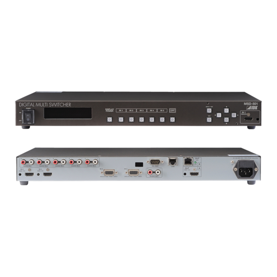
DIGITAL MULTI SWITCHER
POWER
ON
OFF
DIGITAL MULTI SWITCHER
POWER
ON
OFF
● Thank you for choosing our presentation switcher.
● To ensure the best performance of this product, please read this User's Guide fully and carefully before
using it and keep this manual beside the product.
DISPLAY
IN 1
IN 2
POWER
DISPLAY
POWER
1
2
DIGITAL MULTI SWITCHER
POWER
ON
OFF
DIGITAL MULTI SWITCHER
POWER
ON
OFF
MSD-501/502/701/702
MENU / SET
IN 3
IN 4
IN 5
OFF
ESC
IN 1
IN 2
IN 3
IN 4
IN 5
OFF
OUT 1
OUT 2
DISPLAY
IN 1
IN 2
IN 3
IN 4
POWER
DISPLAY
DISPLAY
IN 1
IN 1
IN 2
IN 2
POWER
POWER
1
2
IDK Corporation
Presentation Switcher
MSD-501
IN 1
HDMI/DVI
MSD-502
MENU / SET
IN 1
HDMI/DVI
ESC
MENU / SET
IN 5
IN 6
IN 7
OFF
ESC
IN 3
IN 3
IN 4
IN 4
IN 5
IN 5
IN 6
IN 6
IN 7
IN 7
OFF
OFF
MENU / SET
OUT 1
OUT 2
<User's Guide>
Ver.1.0.0
MSD-701
IN 1
HDMI/DVI
MSD-702
IN 1
HDMI/DVI
ESC
ESC
Advertisement
Table of Contents


Need help?
Do you have a question about the MSD-501 and is the answer not in the manual?
Questions and answers