Table of Contents
Advertisement
Quick Links
Download this manual
See also:
Command Manual
DIGITAL
DISPLAY
POWER
MULTI
SWITCHER
1
2
POWER
3
ON
OFF
4
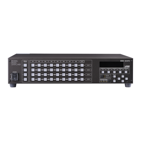
●Thank you for choosing our presentation switcher.
●To ensure the best performance of this product, please read this Users Guide and Command Guide fully and
carefully before using your switcher and keep this manual beside the product.
IN1
IN2
IN3
IN4
IN5
MSD-804FD
IN6
IN7
IN8
OFF
IDK Corporation
Presentation Switcher
<User's Guide>
OUT1
COMMAND
COMMAND
A
B
OUT2
OUT3
COMMAND
PRESET LOAD
OUT4
SWITCHING MODE
V&A
VIDEO
AUDIO
Ver. 1.0.0
MSD-804FD
COMMAND
COMMAND
COMMAND
C
D
E
MENU/SET
ESC
Advertisement
Table of Contents

Subscribe to Our Youtube Channel
Related Manuals for IDK msd-804fd


Summary of Contents for IDK msd-804fd
- Page 1 Presentation Switcher MSD-804FD <User’s Guide> Ver. 1.0.0 DIGITAL MSD-804FD DISPLAY POWER MULTI SWITCHER OUT1 COMMAND COMMAND COMMAND COMMAND COMMAND OUT2 POWER OUT3 MENU/SET COMMAND PRESET LOAD OUT4 SWITCHING MODE V&A VIDEO AUDIO ●Thank you for choosing our presentation switcher. ●To ensure the best performance of this product, please read this Users Guide and Command Guide fully and carefully before using your switcher and keep this manual beside the product.
- Page 2 MSD-804FD User’s Guide Trademarks ● The terms HDMI and HDMI High-Definition Multimedia Interface, and the HDMI Logo are trademarks or registered trademarks of HDMI Licensing, LLC in the United States and other countries. ● PJLink is a trademark in Japan, the United States, and other countries/regions.
- Page 3 ● Some of the contents in this user’s guide such as appearance diagrams, menu operations, communication commands, and so on may differ from the MSD depending on the version. ● This Users guide is subject to change without notice. You can download the latest version from IDK’s website at: http://www.idk.co.jp/en/index.html...
-
Page 4: Safety Instructions
MSD-804FD User’s Guide Safety instructions Read and understand all safety and operating instructions before using this product. Follow all instructions and cautions as detailed in this document. Enforcement Symbol Description Indicates the presence of a hazard that may result in death or serious... - Page 5 The product is intended to be installed by skilled technicians. For installation, please contact a system integrator or IDK. Otherwise, it may cause fire, electric shock, injury, or property damage. Set the power plug in a convenient place to unplug easily.
- Page 6 MSD-804FD User’s Guide Caution Do not place the product in any place where it will be subjected to high temperatures. If the product is subjected to direct sunlight or high temperatures, it may cause fire. Do not place the product in humid, oil smoke, or dusty place.
- Page 7 MSD-804FD User’s Guide Altitude: Do not place the product at elevations of 2,000 meters (6562 feet) or higher above sea level. Failure to do so may shorten the life of the internal parts and result in malfunctions. Instruction...
-
Page 8: Table Of Contents
MSD-804FD User’s Guide Table of Contents 1 Product outline ............................12 2 Features ..............................13 3 Application example ........................... 14 4 Panels ................................ 15 Front panel ............................15 Rear panel ............................16 5 Installation ..............................18 Connecting digital input/output devices..................... 18 RS-232C communication specification ..................... - Page 9 MSD-804FD User’s Guide 7.3.11 Output size [OUTPUT SIZE] ....................... 67 7.3.12 Output masking [OUTPUT MASKING] ..................68 7.3.13 Output automatic sizing [OUTPUT AUTO SIZING] ..............69 7.3.14 Background color [BACKGROUND COLOR] ................70 7.3.15 Test pattern [TEST PATTERN] ....................71 7.3.16 Multi display mode [MULTI DISPLAY] ..................
- Page 10 MSD-804FD User’s Guide 7.8.5 Output lip sync [OUTPUT LIP SYNC] ..................115 7.8.6 Input lip sync [INPUT LIP SYNC] ....................116 7.8.7 Sampling frequency of analog audio input [SAMPLING FREQUENCY] ........117 7.8.8 Audio output connector [OUTPUT CONNECTOR] ..............118 7.8.9...
- Page 11 MSD-804FD User’s Guide 7.14.6 Input bitmap channel assignment [CHANNEL ASSIGN] ............194 7.14.7 Bitmap output at startup [POWER ON BITMAP] ..............195 7.14.8 Dividing memory area [DIVIDE MEMORY] ................196 7.14.9 Input image capture [VIDEO CAPTURE] ................. 199 7.15 Startup Settings ..........................202 7.15.1 DISPLAY POWER keys [DISPLAY POWER] ................
-
Page 12: Product Outline
MSD-804FD User’s Guide 1 Product outline MSD-804FD (hereafter referred to as “the MSD”) is a presentation switcher having a built-in scan converter. For video output, 8 digital inputs are mounted, and HDMI and DVI signals are supported. Input video signal is converted up to QWXGA or 1080p and HDMI/DVI signal can be output. -
Page 13: Features
MSD-804FD User’s Guide 2 Features ■ Video ・ Up to QWXGA(Reduced Blanking), 1080p ・ Digital cable EQ Input: up to 32.8 ft. to 98.43 ft. approx. (10 m to 30 m) Output: up to 32.8 ft. to 164 ft. approx. (10 m to 50 m) ・... -
Page 14: Application Example
MSD-804FD User’s Guide 3 Application example External Audio input control Video/Audio input CD player RS-232C Video/Audio output DIGITAL MSD-804FD DISPLAY POWER MULTI SWITCHER HDMI OUT1 COMMAND COMMAND COMMAND COMMAND COMMAND OUT2 POWER OUT3 M ENU/SET COM MA ND PRESET L OAD... -
Page 15: Panels
MSD-804FD User’s Guide 4 Panels Front panel ② ④ ⑦ ⑥ DIGITAL MSD-804FD DISPLAY POWER MULTI SWITCHER OUT1 ⑤ COMMAND COMMAND COMMAND COMMAND COMMAND OUT2 POWER ⑩ OUT3 MENU/SET COMMAND PRESET LOAD OUT4 SWITCHING MODE V&A VIDEO AUDIO ① ③... -
Page 16: Rear Panel
When a DVI display device is connected, DVI signals are output automatically. ④ HDBaseT output connectors (HDBaseT OUT1 B to OUT4 B) Output connectors for extension (for receivers of HDC series, IDK’s twisted pair cable). HDBaseT output is an optional extra. - Page 17 MSD-804FD User’s Guide ⑪ Frame ground (FG) For indoor ground terminal. *The HDMI I/O connectors support HDCP (High-bandwidth Digital Content Protection), which is a copy protection technique developed by Intel. If DVDs or other contents with copyright protection are played, both source devices (such as DVD players connected to input connectors) and display devices (connected to output connectors) are required to be HDCP compliant.
-
Page 18: Installation
For digital input, HDMI connector is used while HDMI connecter and RJ-45 connector are employed for digital output. These connectors can input/output HDMI signals and DVI signals. HDBaseT output: connected to IDK’s twisted pair cable receiver (HDC series) and can be extended up to 328 ft. approx. (100 m). - Page 19 Note: HDBaseT output does not support DVI signals whose content is protected by HDCP. If you need to extend DVI signal with HDCP, please use the IDK’s HDC-RD100 as a receiver. For HDMI I/O, please use the cable with HDMI Type A (male) connector. For cables longer than 16.4 ft. (5 m), use our recommended cable, AWG24*.
- Page 20 MSD-804FD User’s Guide The HDMI cable does not have lock mechanism, but the provided cable clamp prevents the cable from falling off. [Fig. 5.2] Cable clamp ■ Attaching cable clamp 1. Remove the ring from the clamp and pass it through the clamp as indicated below.
- Page 21 MSD-804FD User’s Guide 3. Attach the HDMI cable and ring to the bar and plug the cable.
-
Page 22: Rs-232C Communication Specification
MSD-804FD User’s Guide RS-232C communication specification External control via RS-232C is available. Connect control devices such as PCs and the MSD with a serial communication cable, and then control the MSD and acquire status using commands. For character notations of commands and configuring communication of serial terminal, see ASCII codes and “7.10 RS-232C”, respectively. -
Page 23: Lan Communication Specification
MSD-804FD User’s Guide LAN communication specification External control via LAN is available. Use a serial communication cable to connect control devices such as PCs and the MSD, and then control the MSD and get its status using commands. For character notation of commands, refer to the ASCII codes or control using commands, use ports 6000 to 6999, 1100, and 23. - Page 24 MSD-804FD User’s Guide Your PC software MSD-804FD → (1 port is occupied → 7 TCP-IP connection ports free) → Sending command (@xxx) ← Sending reply command (@xxx) → (1 port is released → 8 Closing TCP-IP ports are free) [Table 5.3] Increasing connections...
-
Page 25: Basic Operations
MSD-804FD User’s Guide 6 Basic operations Selecting input channels Step 1: Select the desired mode by the SWITCHING MODE key. Every time you press the key, the mode changes sequentially as follows: V&A (video & audio simultaneously; set by default) -
Page 26: Menu Operation
MSD-804FD User’s Guide Menu operation VFD screen MSD-804FD COMMAND COMMAND COMMAND COMMAND COMMAND Menu operation keys M ENU/SET COM MA ND PRESET L OAD SWITCHING MODE V&A VIDEO A UDIO [Fig. 6.2] Menu operation keys MENU/SET key: Displays menus and sets values “ESC”... -
Page 27: Turning On/Off Display Devices
MSD-804FD User’s Guide Turning ON/OFF display devices Use the “DISPLAY POWER” keys to turn on/off the connected display devices. DIGITAL DISPLAY POWER MULTI SWITCHER Controlling power supply switches of display devices POWER [Fig.6.3] DISPLAY POWER keys for display devices Since no values are registered at the factory, in order to use the front panel DISPLAY POWER keys, the settings for those keys must be first registered into system memory (“7.12.3 Control command association... -
Page 28: Command Control
MSD-804FD User’s Guide Command control You can register up to nine control commands in MSD (COMMANDs A to I), but you can execute only five commands (COMMANDs A to E) with control front panel command execution keys. To execute COMMANDs F to I, perform “7.12.4 Command execution [COMMAND EXECUTION]”... -
Page 29: Loading Cross Point
MSD-804FD User’s Guide Loading cross point You can register up to eight cross points in the MSD, but the MSD can only load cross points 1 to 5 by cross point load keys. To load cross points 6 to 8, use menu settings in the “Load cross point” section (“7.13.1 Loading cross point [LOAD CROSS POINT]”) or use RS-232C, or LAN. -
Page 30: Web Browser Control
MSD-804FD User’s Guide Web browser control The MSD connected through LAN can be controlled from a WEB browser such as Microsoft Internet Explorer. To open the operation window, open a WEB browser in the PC through the same LAN network and enter the MSD’s IP address into the address bar. - Page 31 MSD-804FD User’s Guide ① SWITCHING MODE Sets and displays channel switching mode. Does not affect switching mode of the front panel. V&A (switching video & audio simultaneously), VIDEO (switching only video), AUDIO (switching only audio) ② Selecting input channel (OFF, IN1 to IN8) Selects video and audio output.
- Page 32 MSD-804FD User’s Guide [Fig.6.7] Window for editing names ① Input channel name (INPUT1 to INPUT8) Enter the desired input names which will be displayed in “CROSS POINT” on “WEB browser control window”. IN1 to 9 are set by factory default.
- Page 33 MSD-804FD User’s Guide ③ Control command name (COMMAND A to COMMAND I) Enter the desired input names which will be displayed in “COMMAND EXECUTE” on “WEB browser control window”. “A” to “I” are set by factory default. ④ SEND Saves the names entered above (1 to 3).
-
Page 34: Factory Reset
MSD-804FD User’s Guide Factory reset You can restore settings of “6.1 Selecting input channels”, ”6.6 Locking/unlocking front keys”, and “7 Settings” to the factory default by turning on the MSD while pressing the ESC key. Hold the ESC key until you hear long-tone buzzer sound. The sound stops when the initialization is completed, and the MSD starts its normal operation. - Page 35 MSD-804FD User’s Guide [Table 6.2] Factory default (2/5) Set for each Function Factory default I/O/bmp* INPUT VIDEO DETECT 10000 ms. (10 seconds) HDCP INPUT ENABLE ENABLE INPUT EQUALIZER INPUT OFF CHECK H START 0 (when signals are detected, it is set automatically)
- Page 36 MSD-804FD User’s Guide [Table 6.3] Factory default (3/5) Set for each Function Factory default I/O/bmp* OUTPUT LEVEL ±0 dB OUTPUT MUTE AUTO (For HDMI signals, digital audio is effective; for AUDIO INPUT SELECT other signals, analog audio is effective) INPUT OFFSET ±0 dB...
- Page 37 MSD-804FD User’s Guide [Table 6.4] Factory default (4/5) Set for Function Factory default each I/O/bmp* COMMAND EDIT All 32 commands are not registered. RECV COMMAND EDIT All 32 commands are not registered. COMMAND LINK All 90 commands are not registered.
-
Page 38: Startup Time
MSD-804FD User’s Guide [Table 6.4] Factory default (5/5) Set for Function Factory default each I/O/bmp* BITMAP OUTPUT BACKGROUND COLOR R/G/B: 255 (white) ASPECT AUTO POSITION CENTER CHANNEL ASSIGN NONE (Not assigned) POWER ON BITMAP Divide: None DIVIDE MEMORY Memory size: Assigns 128 blocks to 1 bitmap... -
Page 39: Settings
MSD-804FD User’s Guide 7 Settings Menu list MSD-804FD [FUNCTION SELECT] [OUTPUT TIMING] [OUT1 RESOLUTION] →Output resolution [RESOLUTION] OUTPUT TIMING RESOLUTION AUTO-A(1080i 59.94) ▲ [OUTPUT TIMING] [OUT1 MONITOR] →Aspect ratio control of output video MONITOR ASPECT RESOLUTION [MONITOR ASPECT] ▲ [OUTPUT TIMING] [IN1 ASPECT] →... - Page 40 MSD-804FD User’s Guide [FUNCTION SELECT] [IMAGE EFFECT] [IN1 BRIGHTNESS] →Input brightness [INPUT BRIGHTNESS] IMAGE EFFECT INPUT BRIGHTNESS 100% ▲ [IMAGE EFFECT] [IN1 CONT] LINK:ON →Input contrast [INPUT CONTRAST] INPUT CONTRAST R:100 G:100 B:100 ▲ [IMAGE EFFECT] [IN1 HUE] →Hue [INPUT HUE] INPUT HUE 0°...
-
Page 41: Video Output
MSD-804FD User’s Guide [FUNCTION SELECT] [OUTPUT SETTING] [OUT1A EQUALIZER] →Output equalizer [OUTPUT OUTPUT SETTING OUTPUT EQUALIZER EQUALIZER] ▲ [OUTPUT SETTING] [OUT1A MODE] →Output mode [OUTPUT MODE] OUTPUT MODE HDMI YCbCr4:4:4 MODE ▲ [OUTPUT SETTING] [OUT1 SYNC OUTPUT] →Synchronous signal output... - Page 42 MSD-804FD User’s Guide [FUNCTION SELECT] [AUDIO] [OUT1 AUDIO VOLUME] →Audio output level [OUTPUT LEVEL] AUDIO OUTPUT LEVEL ▲ [AUDIO] [OUT1 MUTE] →Mute [OUTPUT MUTE] OUTPUT MUTE ▲ [AUDIO] [IN1 AUDIO SELECT] →Audio input selection [AUDIO AUDIO INPUT SELECT AUTO(DIGITAL) INPUT SELECT] ▲...
-
Page 43: Gateway Address
MSD-804FD User’s Guide →RS-232C communication [FUNCTION SELECT] [COM PORT] [CH1 PARAMETERS] COM PORT PARAMETERS 9600 8 NONE settings [PARAMETERS] ▲ [COM PORT] [CH1 FUNCTION] →RS-232C operation mode ▲ FUNCTION RECIEVER [FUNCTION] ▲ [FUNCTION SELECT] [LAN] [LAN IP ADDRESS] →IP address [IP ADRESS] IP ADDRESS 192.168. - Page 44 MSD-804FD User’s Guide [FUNCTION SELECT] [PRESET MEMORY] [LOAD CROSS POINT] →Loading cross point PRESET MEMORY LOAD CROSS POINT No.1 [LOAD CROSS POINT] ▲ [PRESET MEMORY] [SAVE CROSS POINT] →Saving cross point SAVE CROSS POINT No.1 [SAVE CROSS POINT] ▲ [PRESET MEMORY] [EDIT CROSS POINT] →Editing cross point...
- Page 45 MSD-804FD User’s Guide [FUNCTION SELECT] [OTHERS] [KEY LOCK MODE] →Setting key lock mode [KEY LOCK MODE] OTHERS KEY LOCK MODE CHANNEL :LOCK ▲ [OTHERS] [BUZZER] →Key buzzer [BUZZER] BUZZER ▲ →Automatic key lock for control command [OTHERS] [COMMAND AUTO LOCK]...
- Page 46 MSD-804FD User’s Guide You can set the menu for each digital input and analog input For each digital input/analog input/input signals only digital input) separately. Menus which can be set for each OUTA and OUTB separately, is displayed differently depending on whether HDBaseT output (optional extra) is mounted or not.
-
Page 47: Input Signal Automatic Detection
MSD-804FD User’s Guide Input Signal Automatic Detection The MSD continuously monitors input signals. If input signals that have been input before, they are output with the same size and quality of view used previously. If input signals are not matched with any signal settings that have been input before, only settings of input timing is initialized and other settings are not changed. -
Page 48: Setting Position, Size, And Masking
MSD-804FD User’s Guide Setting Position, Size, and Masking Position, size, and masking can be set for each input and output. Normally, set them for each input. If edges are cut off due to enlarged display in the display device side or if enlarging output video for all inputs at once, set them for the output side. - Page 49 MSD-804FD User’s Guide [If edges are cut off due to enlargement in the display device side] If video is input to a wide TV or the like, the video is automatically enlarged and displayed, and sometimes edges are cut off. In this case, change the display size (such as “Full display”, “Wide display”). If the problem is still not resolved, set “7.3.10 Output position [OUTPUT POSITION]”...
-
Page 50: Output Resolution [Resolution]
QWXGA@60 are output with Reduced Blanking. Note 1: If connecting an IDK’s distribution amplifier between the MSD and display device and set the resolution to “AUTO”, set the EDID of the distribution amplifier to “EXTERNAL” which enables the MSD to load the EDID from the display device. - Page 51 MSD-804FD User’s Guide 1. To set output resolution using menu: MSD-804FD ↓ SET key keys: Select “OUTPUT TIMING”. [FUNCTION SELECT] OUTPUT TIMING ↓ SET key keys: Select “RESOLUTION”. [OUTPUT TIMING] RESOLUTION ↓ SET key ▲▼keys: Select the desired resolution. [OUT1 RESOLUTION] AUTO-A(1080i 59.94)
-
Page 52: Aspect Ratio Control Of Output Video [Monitor Aspect]
MSD-804FD User’s Guide For each output (common to OUTA and OUTB 7.3.2 Aspect ratio control of output video [MONITOR ASPECT] This setting will be used to restore the aspect ratio to the normal ratio in “7.3.3 Aspect ratio control of input video [INPUT ASPECT]”. -
Page 53: Aspect Ratio Control Of Input Video [Input Aspect]
MSD-804FD User’s Guide For each input port/input signal 7.3.3 Aspect ratio control of input video [INPUT ASPECT] ・AUTO-1 [Default] ・14:9 ・14:9 SIDE PANEL ・AUTO-2 ・16:9 LETTER BOX ・FULL ・4:3 ・14:9 LETTER BOX ・THROUGH ・16:9 ・4:3 SIDE PANEL If you select “AUTO-1” or “AUTO-2”, the aspect ratio will be restored automatically to the original ratio according to the settings of “7.3.2 Aspect ratio control of output video [MONITOR ASPECT]”... - Page 54 MSD-804FD User’s Guide [Selecting “LETTER BOX/SIDE PANEL” for aspect ratio restoration processing] Aspect ratio of destination display device* Input signal 16:9 16:10 AUTO-1 Cut: top&bottom Cut: top&bottom Cut: top&bottom Cut: top&bottom Cut: top&bottom BC: top&bottom BC: top&bottom BC: top&bottom BC: top&bottom...
- Page 55 MSD-804FD User’s Guide [Selecting “SIDE CUT/TOP BOTTOM CUT” for aspect ratio restoration processing] Aspect ratio of destination display device* Input signal 16:9 16:10 16:10 video signal Cut: right&left Cut: right&left Cut: top&bottom Cut: top&bottom 14:9 video signal Cut: right&left Cut: right&left Cut:top&bottom...
- Page 56 MSD-804FD User’s Guide Even with “AUTO-1” or “AUTO-2”, the aspect ratio is not restored if recognition signals with valid aspect ratio is not input. If HDMI signals (SDTV) is input, the MSD performs in the same way as when the input aspect ratio is 4:3;...
- Page 57 MSD-804FD User’s Guide Note: If you select “THROUGH”, the input video is displayed with pixel ratio of 1:1 regardless of settings of “7.3.2 Aspect ratio control of output video [MONITOR ASPECT]” and “7.3.4 Aspect ratio control [ASPECT PROCESS]”. 1. To set the aspect ratio control using menu: MSD-804FD ↓...
-
Page 58: Aspect Ratio Control [Aspect Process]
MSD-804FD User’s Guide 7.3.4 For each input port/input signal Aspect ratio control [ASPECT PROCESS] You can select a processing of aspect ratio control. ・Letter box/Side panel: L-BOX/S-PANEL [Default] ・Side cut/Top bottom cut: S-CUT/TB-CUT “L-BOX/S-PANEL”: The input video is displayed in the center, and the background color set in ”7.3.14 Background color [BACKGROUND COLOR]“... -
Page 59: Overscan [Input Over Scan]
MSD-804FD User’s Guide For each input port/input signal 7.3.5 Overscan [INPUT OVER SCAN] ・The enlargement rate: 100% to 115% [Default values]: 105% for SDTV 100% for HDTV/VESA: On the full screen The effective display areas of SDTV are narrowed slightly during edit. If they are displayed without any change, areas without videos (usually black bars) are displayed on edges. -
Page 60: Input Position [Input Position]
MSD-804FD User’s Guide For each input port/input signal 7.3.6 Input position [INPUT POSITION] You can set the position for each input video by using this menu or for each output by following “7.3.10 Output position [OUTPUT POSITION]”. Normally, set the position, size, and masking of each input in settings of each input. -
Page 61: Input Size [Input Size]
MSD-804FD User’s Guide Keys: Set the vertical position of IN1. [IN1 POSITION] 0 V: ↓ ESC key: Returns to the previous screen 2. To set the input video position (pixel position) using commands: @SNP: Set input position @GNP: Get input position For each input port/input signal 7.3.7... - Page 62 MSD-804FD User’s Guide The set range and default value depend on settings of ”7.3.1 Output resolution [RESOLUTION]”, and the range is quarter to quadruple of the output resolution. Default is the same as the resolution setting, and the video is displayed on the full screen of the display device.
-
Page 63: Input Masking [Input Masking]
MSD-804FD User’s Guide For each input port/input signal 7.3.8 Input masking [INPUT MASKING] Any unnecessary area (top/bottom and right/left) can be hidden by using the masking setting. You can set the masking amount for each input by using this menu or for each output by following “7.3.12 Output masking [OUTPUT MASKING]”. -
Page 64: Input Automatic Sizing [Input Auto Sizing]
MSD-804FD User’s Guide keys: Set the top side masking of IN1. [IN1 MASKING] L: R:1920 T: B:1080 ↓ keys keys : : Set the bottom side masking of IN1. [IN1 MASKING] L: R:1920 T: B:1080 ↓ ESC key: Returns to the previous screen 2. - Page 65 MSD-804FD User’s Guide [Horizontal position] [Vertical position] [Fig. 7.11] Output size The settable range depends on settings of “7.3.1 Output resolution [RESOLUTION]” and “7.3.11 Output size [OUTPUT SIZE]”. Values can be set unless video disappears from the top, bottom and right, left of the screen.
- Page 66 MSD-804FD User’s Guide 1. To set the output position on the output screen (pixel position) using menu: MSD-804FD ↓ SET key [FUNCTION SELECT] ▲▼keys: Select “OUTPUT TIMING”. OUTPUT TIMING ↓ SET key [OUTPUT TIMING] ▲▼keys: Select “OUTPUT POSITION”. OUTPUT POSITION ↓...
-
Page 67: Output Size [Output Size]
MSD-804FD User’s Guide For each output (common to OUTA and OUTB) 7.3.11 Output size [OUTPUT SIZE] Output video size is scalable in reference to the upper left of video set in “7.3.10 Output position [OUTPUT POSITION]”. You can set the size for each output by using this menu or for each input by using “7.3.7 Input size [INPUT SIZE]”. -
Page 68: Output Masking [Output Masking]
MSD-804FD User’s Guide If you set “LINK” to ON”, only horizontal size can be set. If you set the horizontal size, the current aspect ratio is kept and vertical size is also set. If either horizontal or vertical size reaches the limit, you cannot set the larger values. -
Page 69: Output Automatic Sizing [Output Auto Sizing]
MSD-804FD User’s Guide [OUTPUT TIMING] ▲▼keys: Select “OUTPUT MASKING”. OUTPUT MASKING ↓ SET key [OUT1 MASKING]L: ▲▼keys: Set the left side masking of OUT1. R:1920 T: 0 B:1080 ↓ ◄►keys [OUT1 MASKING]L: ▲▼keys: Set the right side masking of OUT1. -
Page 70: Background Color [Background Color]
MSD-804FD User’s Guide For each output (common to OUTA and OUTB) 7.3.14 Background color [BACKGROUND COLOR] You can select a color from an approximately 16.7-million combinations of Red, Green, and Blue. ▪ Background color: Red, Green, and Blue: 0 to 255 [Default]: all colors: 0 1. -
Page 71: Test Pattern [Test Pattern]
MSD-804FD User’s Guide For each output (common to OUTA and OUTB) 7.3.15 Test pattern [TEST PATTERN] You can scroll at a speed of 3 to 30 pixels/a frame by using ”COLOR BAR”, “GRAY SCALE”, “LAMP”, and “ZEBRA”. ・OFF [Default] ・V-COLOR BAR ・100% WHITE RASTER... - Page 72 MSD-804FD User’s Guide 1. To set the test pattern using menu: MSD-804FD ↓ SET key [FUNCTION SELECT] ▲▼keys: Select “OUTPUT TIMING”. OUTPUT TIMING ↓ SET key [OUTPUT TIMING] ▲▼keys: Select “TEST PATTERN”. TEST PATTERN ↓ SET key [OUT1 PATTERN] ▲▼keys: Select the desired test pattern for OUT1.
-
Page 73: Multi Display Mode [Multi Display]
MSD-804FD User’s Guide 7.3.16 Multi display mode [MULTI DISPLAY] You can set Multi display mode. Once this mode is set to ON, settings of the following menus will be applied to all outputs; they cannot be set separately. ・Multi display mode: OFF [Default] ・Multi display mode: ON... - Page 74 MSD-804FD User’s Guide 1. To set the multi display mode using menu: MSD-804FD ↓ SET key keys: Select “OUTPUT TIMING”. [FUNCTION SELECT] OUTPUT TIMING ↓ SET key keys: Select “MULTI DISPLAY”. [OUTPUT TIMING] MULTI DISPLAY ↓ SET key keys: Set “MULTI DISPLAY” to “OFF” or “ON”.
-
Page 75: Video Correction
MSD-804FD User’s Guide Video Correction You can set output video quality. Items that are set for each input: Correct deviation in color and others. Items that are set for each output: Correct brightness according to the connected display device and others. - Page 76 MSD-804FD User’s Guide 1. To set the input contrast using menu: MSD-804FD ↓ SET key [FUNCTION SELECT] ▲▼keys: Select “IMAGE EFFECT”. IMAGE EFFECT ↓ SET key [IMAGE EFFECT] ▲▼keys: Select “INPUT CONTRAST”. INPUT CONTRAST ↓ SET key [IN1 CONT] LINK:ON ▲▼keys: Set “LINK”...
-
Page 77: Hue [Input Hue]
MSD-804FD User’s Guide 7.4.3 Hue [INPUT HUE] For each input port/input signal You can set the hue of input video: ▪ HUE: 0° to 359° [Default]: 0° 1. To setting the hue using menu: MSD-804FD ↓ SET key [FUNCTION SELECT] ▲▼keys: Select “IMAGE EFFECT”. -
Page 78: Saturation [Input Saturation]
MSD-804FD User’s Guide 7.4.4 For each input port/input signal Saturation [INPUT SATURATION] You can set the saturation of input video: ▪ Saturation: 0% to 200% [Default]: 100% If you reduce the value, the color becomes weaker and goes to monochrome. (0%: full monochrome) If you increase the value, the color becomes more vivid. -
Page 79: Black Level [Input Setup Level]
MSD-804FD User’s Guide For each input port/input signal 7.4.5 Black level [INPUT SETUP LEVEL] You can set the black level of the input video: ▪ Setup level: -10.0% to +10.0% by 0.5% step [Default]: ±0.0% If black level of output video is low (light black), set the level toward the minus direction. -
Page 80: Input Default Color [In Default Color]
MSD-804FD User’s Guide For each input port/input signal 7.4.6 Input default color [IN DEFAULT COLOR] You can initialize settings of the following menus: “7.4.1 Input brightness [INPUT BRIGHTNESS]”, “7.4.2Input contrast [INPUT CONTRAST]”, “7.4.3 Hue [INPUT HUE]”, “7.4.4 Saturation [INPUT SATURATION]”, and “7.4.5 Black level [INPUT SETUP LEVEL]”. -
Page 81: Output Brightness [Output Brightness]
MSD-804FD User’s Guide 7.4.7 For each output (common to OUTA and OUTB) Output brightness [OUTPUT BRIGHTNESS] ▪ Brightness: 80% to 120% [Default]: 100% If you increase the value, the whole level will be increased as well; if you reduce the value, the whole level will be reduced. -
Page 82: Output Contrast [Output Contrast]
MSD-804FD User’s Guide 7.4.8 For each output (common to OUTA and OUTB) Output contrast [OUTPUT CONTRAST] You can set Red, Green, and Blue separately. ・Contrast (Red): 0% to 200% [Default]: 100% ・Contrast (Green): 0% to 200% [Default]: 100% ・Contrast (Blue): 0% to 200% [Default]: 100% If you reduce the set value, the amplitude decreases and if you increase the value, the amplitude increases. -
Page 83: Output Default Color [Out Default Color]
MSD-804FD User’s Guide For each output (common to OUTA and OUTB) 7.4.9 Output default color [OUT DEFAULT COLOR] You can initialize the settings of “7.4.7 Output brightness [OUTPUT BRIGHTNESS]” and “7.4.8 Output contrast [OUTPUT CONTRAST]”. 1. To initialize the settings of output default color using menu: MSD-804FD ↓... -
Page 84: Input Settings
MSD-804FD User’s Guide Input Settings For each input 7.5.1 No-signal input monitoring [INPUT VIDEO DETECT] If you change the settings of EDID or turn off/on the MSD while HDMI or DVI devices (hereafter referred to as “source devices”) that are connected to the MSD are turned on, only a few source devices stop outputting signals. - Page 85 MSD-804FD User’s Guide 1. To set the No-signal input monitoring time using menu: MSD-804FD ↓ SET key [FUNCTION SELECT] ▲▼ keys: Select “INPUT SETTING”. INPUT SETTING ↓ SET key [INPUT SETTING] ▲▼ keys: Select “INPUT VIDEO DETECT”. INPUT VIDEO DETECT ↓...
-
Page 86: Hdcp Input Enabled/Disabled [Hdcp Input Enable]
MSD-804FD User’s Guide 7.5.2 For each input HDCP input enabled/disabled [HDCP INPUT ENABLE] Some source devices check whether the connected device supports HDCP and then determine whether they encrypt HDCP signals or not. Since the MSD is HDCP compliant, if it is connected to a display device that is not HDCP compliant, the display device may not display video. -
Page 87: Input Equalizer [Input Equalizer]
MSD-804FD User’s Guide For each input 7.5.3 Input equalizer [INPUT EQUALIZER] HDMI input connector has an equalizer circuit to correct attenuated signals caused when a long cable is connected. If you set this menu to “ON”, signals are corrected automatically according to the amount of the attenuation. -
Page 88: Automatic Detection Of Input Video Interruption [Input Off Check]
MSD-804FD User’s Guide 7.5.4 For each input Automatic detection of input video interruption [INPUT OFF CHECK] The MSD can stop outputting video immediately after input video signals are disconnected for a moment. Use this function to reduce distorted output video occurred at the time of switching if an external switcher is connected for input of the MSD. -
Page 89: Input Timing Settings
MSD-804FD User’s Guide Input Timing Settings The MSD monitors signals at all times and sets the input timing automatically. Only if part of the video is cut off, adjust the input timing finely by using this menu. For each input port/input signal 7.6.1... -
Page 90: Horizontal Start Position [H Start]
MSD-804FD User’s Guide For each input port/input signal 7.6.2 Horizontal start position [H START] ・Starting position of horizontal reading: 64 to 2900 (Must be equal or less than [The total number of horizontal dots - Horizontal display period]) [Default]: Depends on input signals... -
Page 91: Horizontal Display Period [H Display]
MSD-804FD User’s Guide For each input port/input signal 7.6.3 Horizontal display period [H DISPLAY] ・Horizontal display period: 64 to 2900 (Equal or less than [The total number of horizontal dots - 64]) [Default]: Depends on input signals Total horizontal dots... -
Page 92: Vertical Start Position [V Start]
MSD-804FD User’s Guide For each input port/input signal 7.6.4 Vertical start position [V START] ・Vertical start position: 10 to 2048 (Equal or less than [Total vertical lines-vertical display period]) [Default]: Depends on input signals Total vertical lines Vertical display period... -
Page 93: Vertical Display Period [V Display]
MSD-804FD User’s Guide For each input port/input signal 7.6.5 Vertical display period [V DISPLAY] ・Vertical display period: 10 to 2048 (Equal or less than [The total number of vertical lines – 10]) [Default]: Depends on input signals Total vertical lines... -
Page 94: Initialization [Initialize]
MSD-804FD User’s Guide For each input port/input signal 7.6.6 Initialization [INITIALIZE] The MSD initializes the input timing that were set manually. 1. To initialize the input timing using menu: MSD-804FD ↓ SET key keys: Select “INPUT TIMING”. [FUNCTION SELECT] INPUT TIMING ↓... -
Page 95: Output Settings
MSD-804FD User’s Guide Output Settings For each output (only OUTA) 7.7.1 Output equalizer [OUTPUT EQUALIZER] HDMI input connector has an equalizer circuit to correct attenuated signals caused when a long cable is connected. Set the output equalizer according to the cable length. -
Page 96: Output Mode [Output Mode]
MSD-804FD User’s Guide For each output (OUTA and 7.7.2 Output mode [OUTPUT MODE] OUTB separately) You can select the output mode of HDMI output connectors manually. Set the mode to “HDMI YCbCr4:4:4 MODE” to output video with the optimal mode automatically even if a display device that does not support HDMI component signals or DVI signals is connected. -
Page 97: Synchronous Signal Output With No Input Video [Sync Output]
MSD-804FD User’s Guide For each output (common to 7.7.3 Synchronous signal output with no input video [SYNC OUTPUT] OUTA and OUTB) You can set whether synchronous signals are output when no video signal is input from the selected input, or when ”OFF”... -
Page 98: Output Video With No Input Video [Video Output]
MSD-804FD User’s Guide For each output (common to OUTA and OUTB) 7.7.4 Output video with no input video [VIDEO OUTPUT] You can set the color of the video to be output when no video signal is input from the selected input.* ・Black screen: BLACK... -
Page 99: Window Transition Effect [Video Switching]
MSD-804FD User’s Guide For each output (common to OUTA and OUTB) 7.7.5 Window transition effect [VIDEO SWITCHING] You can select a window transition effect for when the video input is switched. Switching speed of effect other than “CUT” can be set in “7.7.6 Window transition speed [SWITCHING SPEED]”. -
Page 100: Window Transition Speed [Switching Speed]
MSD-804FD User’s Guide For each output (common to OUTA and OUTB) 7.7.6 Window transition speed [SWITCHING SPEED] You can set the window transition speed for “FADE OUT-IN”, “DISSOLVE”, or “WIPE OUT/IN” when input channel is switched. These options are not available when “7.7.5 Window transition effect [VIDEO SWITCHING]” is set to “CUT”. -
Page 101: Wipe Color [Wipe Color]
MSD-804FD User’s Guide For each output (common to OUTA and OUTB) 7.7.7 Wipe color [WIPE COLOR] You can set the wipe color while switching video input. Valid only if you set “7.7.5 Window transition effect [VIDEO SWITCHING]” to “WIPE”. ・Wipe color Red: 0 to 255 [Default]: 0 ・Wipe color Green: 0 to 255 [Default]: 0... -
Page 102: Video Output Connector [Output Connector]
MSD-804FD User’s Guide For each output (OUTA and OUTB separately) 7.7.8 Video output connector [OUTPUT CONNECTOR] The MSD distributes the same video to 2 outputs, and you can enable or disable video output from each connector. You can check or preview the video by setting this menu to ON for an output. When you decide which video to be displayed for both outputs, then set the other to ON. -
Page 103: Hdcp Output [Hdcp Output Mode]
MSD-804FD User’s Guide For each output (OUTA and OUTB separately) 7.7.9 HDCP output [HDCP OUTPUT MODE] You can set the HDCP output for when a display device that supports HDCP is connected. “ALWAYS”: HDCP is output at all times regardless of status of input signals. -
Page 104: The Number Of Hdcp Retries [Hdcp Error Retry]
MSD-804FD User’s Guide For each output (OUTA and OUTB separately) 7.7.10 The number of HDCP retries [HDCP ERROR RETRY] If a display device with HDCP is connected and you set “7.7.9 HDCP output [HDCP OUTPUT MODE]” to “HDCP INPUT ONLY” or “ALWAYS”, HDCP is authorized regardless of the status of input signals. Normally, set “HDCP ERROR RETRY”... -
Page 105: Deep Color [Deep Color Output]
MSD-804FD User’s Guide For each output (OUTA and OUTB separately) 7.7.11 Deep Color [DEEP COLOR OUTPUT] “30-BIT COLOR”: signals are output with “30-BIT COLOR” only if a display device supporting Deep Color is connected. If a display device that does not support Deep Color is connected, signals are output with “24-BIT COLOR”... -
Page 106: Cec (Consumer Electronics Control) [Cec Connection]
MSD-804FD User’s Guide 7.7.12 CEC (Consumer Electronics Control) [CEC CONNECTION] You can select the channel for connecting CEC when a CEC-supported device with CEC is connected to HDMI input connector, HDMI output connector, and HDBaseT output connectors. CEC can be used only in HDMI connector (HDMI input connector IN1 to IN8, HDMI output connector OUT1A to OUT4A) or when HDC-RH100 is connected to HDBaseT output connector OUT1B to OUT4B. - Page 107 MSD-804FD User’s Guide Note 2: CEC connection is a one-on-one basis; it cannot connect multiple inputs and outputs. If you set multiple outputs to connect to the same input, only a smaller output number is connected preferentially and other outputs are not connected. For example, if you set both OUT1 and OUT2 to IN2, OUT1 is connected to IN2, while OUT 2 is not connected.
-
Page 108: Hdcp Re-Authentication [Hdcp Authorization]
MSD-804FD User’s Guide For each output (OUTA and OUTB separately) 7.7.13 HDCP re-authentication [HDCP AUTHORIZATION] If a display device supporting HDCP is connected, HDCP is authorized automatically. You can re-authorize HDCP manually using this menu. (Connection Reset is performed automatically, but it can be performed manually using this menu.) -
Page 109: Frame Lock Mode [Frame Lock]
MSD-804FD User’s Guide 7.7.14 Frame lock mode [FRAME LOCK] You can set the frame lock mode. ・OFF [Default] ・ON: Synchronous signals of all outputs will be output at the same timing. This mode is for multiple windows configuration and others. Settings of “7.3.1 Output resolution [RESOLUTION]”... -
Page 110: Audio Settings
MSD-804FD User’s Guide Audio settings HDMI digital audio supports the following formats. For audio output of devices connected to the HDMI input connectors (such as DVD players), set a format supported by both the MSD and display device connected to HDMI output connector (such as display devices and AV amplifier). -
Page 111: Audio Output Level [Output Level]
MSD-804FD User’s Guide If bit stream signals (compressed audio) such as Dolby Digital are input to HDMI digital audio, these input audio signals are output to digital audio as they are. They are not output to analog audio, and audio volume cannot be adjusted. -
Page 112: Mute [Output Mute]
MSD-804FD User’s Guide For each output (common to OUTA and OUTB) 7.8.2 Mute [OUTPUT MUTE] ・ Mute OFF: OFF [Default] ・ Mute ON: ON If you set “7.16.6 Top VFD screen [TOP DISPLAY]” to “AUDIO VOLUME,” you can set this menu on the top screen. -
Page 113: Audio Input Selection [Audio Input Select]
MSD-804FD User’s Guide For each input 7.8.3 Audio input selection [AUDIO INPUT SELECT] If you select “AUTO,” digital audio is output automatically when HDMI signals with audio signals are input; analog audio is output in other cases. ・AUTO [Default] ・ANALOG ・DIGITAL... -
Page 114: Audio Input Level [Input Offset]
MSD-804FD User’s Guide For each digital input/analog 7.8.4 Audio input level [INPUT OFFSET] input/input signals only digital input) You can correct the gap in audio input levels of each input signal, because audio input level can be set for each input connector. -
Page 115: Output Lip Sync [Output Lip Sync]
MSD-804FD User’s Guide For each output (common to OUTA and OUTB) 7.8.5 Output lip sync [OUTPUT LIP SYNC] Since video signals and audio signals are processed on different circuits, time lag between the lip movement and audio is developed. The time lag can be corrected by the lip sync correction function. -
Page 116: Input Lip Sync [Input Lip Sync]
MSD-804FD User’s Guide For each input port/input signal 7.8.6 Input lip sync [INPUT LIP SYNC] Normally, audio is delayed depending on the video delay amount of the display device in ”7.8.5 Output lip sync [OUTPUT LIP SYNC]“. If the video source itself includes the gap between video and audio or if video is delayed by connecting a frame synchronizer for the input, set the lip-sync frames individually for each input. -
Page 117: Sampling Frequency Of Analog Audio Input [Sampling Frequency]
MSD-804FD User’s Guide For each output 7.8.7 Sampling frequency of analog audio input [SAMPLING FREQUENCY] (common to OUTA and OUTB) You can set the sampling frequency for when analog audio input signals (you set “7.8.3 Audio input selection [AUDIO INPUT SELECT]” to “ANALOG”) are output to digital audio. If you set it to “AUTO-A” or “AUTO-B”, the maximum sampling frequency supported by the connected display device is output. -
Page 118: Audio Output Connector [Output Connector]
MSD-804FD User’s Guide For each output (common to OUTA 7.8.8 Audio output connector [OUTPUT CONNECTOR] and OUTB) You can select audio output connectors. For digital output, the settings of HDMI output connector and HDBaseT output connector are common. If you want to set them separately, set the audio output connector in “7.8.9 Digital audio output connector... -
Page 119: Digital Audio Output Connector [Digital Output]
MSD-804FD User’s Guide For each output (OUTA and OUTB separately) 7.8.9 Digital audio output connector [DIGITAL OUTPUT] You can enable/disable digital audio output connector. This menu is available only if HDBaseT output option is mounted. ・Digital audio output OFF: OFF ・Digital audio output ON: ON [Default]... -
Page 120: Multi-Channel Audio Output [Multi Audio]
MSD-804FD User’s Guide For each output (common to OUTA and OUTB) 7.8.10 Multi-channel audio output [MULTI AUDIO] You can set audio to be output to a display device that does not support multi-channel linear PCM or analog audio for when multi-channel linear PCM audio is input from an HDMI input connector. -
Page 121: Test Tones [Test Tone]
MSD-804FD User’s Guide For each output (common to OUTA and OUTB) 7.8.11 Test tones [TEST TONE] Since test tone can be output only to specific speakers, you can check the position of the speakers. ・Test tones ・OFF [Default] ・1kHz ・400Hz ・Speaker... - Page 122 MSD-804FD User’s Guide 1. To set the test tone using menu: MSD-804FD ↓ SET key [FUNCTION SELECT] ▲▼keys: Select “AUDIO”. AUDIO ↓ SET key ▲▼keys: Select ”TEST TONE”. [AUDIO] TEST TONE ↓ SET key [OUT1 TEST TONE] ▲▼keys: Select the desired test tone of OUT1.
-
Page 123: Edid (Extended Display Identification Data)
MSD-804FD User’s Guide EDID (Extended Display Identification Data) You can select the EDID from either the built-in data or the data loaded from the connected display device. The MSD can load EDID that conforms to VESA DDC2B/EDID standard ver. 1.0 to 1.3. - Page 124 MSD-804FD User’s Guide 1. To set the EDID using menu: MSD-804FD ↓ SET key [FUNCTION SELECT] ▲▼keys: Select “EDID”. EDID ↓ SET key [EDID] ▲▼keys: Select “EDID DATA”. EDID DATA ↓ SET key ▲▼keys: Select the EDID. [IN1 EDID] INTERNAL EDID ◄►keys: Select the desired input (IN1 to IN8).
-
Page 125: Pc Resolutions [Pc Resolution]
MSD-804FD User’s Guide For each input 7.9.2 PC resolutions [PC RESOLUTION] You can set the resolution to be output from source devices. This menu is valid only if you select “INTERNAL EDID” for “7.9.1 EDID setting [EDID DATA]“. Normally, set the resolution when connecting DVI devices such as PCs. -
Page 126: Input Resolution For Av Devices [Av Resolution]
MSD-804FD User’s Guide 1. To set the PC resolution using menu: MSD-804FD ↓ SET key [FUNCTION SELECT] ▲▼keys: Select “EDID”. EDID ↓ SET key [EDID] ▲▼keys: Select “PC RESOLUTION”. PC RESOLUTION ↓ SET key ▲▼keys: Set the resolution for the PC. - Page 127 MSD-804FD User’s Guide [Table 7.5] Input resolutions with “AUTO” 1024 1280 1280 1280 1280 1280 1360 1366 1400 1440 1600 1600 1680 1920 1920 1920 2048 PC resolution 1024 1050 1200 1050 1080i 1080 1200 1152 AV resolution 480p 720p...
-
Page 128: Deep Color [Deep Color Input]
MSD-804FD User’s Guide For each input 7.9.4 Deep Color [DEEP COLOR INPUT] This menu is valid only all conditions below are met: if you select “INTERNAL EDID” for “7.9.1 EDID setting [EDID DATA]“, you select a resolution other than “UNUSED” for ”7.9.3 Input resolution for AV devices [AV RESOLUTION]”, and you connect an HDMI device such as a Blu-ray recorder. -
Page 129: Audio Format [Audio Format]
MSD-804FD User’s Guide For each input 7.9.5 Audio format [AUDIO FORMAT] You can set the audio format and maximum sampling frequency to be output from a source device. This menu is valid only all conditions below are met: if you select “INTERNAL EDID” for “7.9.1 EDID setting [EDID DATA]“, you select a resolution other than “UNUSED”... - Page 130 MSD-804FD User’s Guide 2. To set the audio format using commands: @SAF: Set audio format @GAF: Get audio format...
-
Page 131: Speaker Configuration [Speaker]
MSD-804FD User’s Guide For each input 7.9.6 Speaker configuration [SPEAKER] This menu is valid only all conditions below are met: if you select “INTERNAL EDID” for “7.9.1 EDID setting [EDID DATA]“, you select a resolution other than “UNUSED” for ”7.9.3 Input resolution for AV devices [AV RESOLUTION]”, and you connect an HDMI device such as a Blu-ray recorder. - Page 132 MSD-804FD User’s Guide 1. To set the speaker configuration using menu: MSD-804FD ↓ SET key [FUNCTION SELECT] ▲▼keys: Select “EDID”. EDID ↓ SET key [EDID] ▲▼keys: Select “SPEAKER”. SPEAKER ↓ SET key ▲▼keys: Select the setting mode of IN1 (AUTO, MANUAL).
-
Page 133: Edid Copy [Monitor Edid Copy]
MSD-804FD User’s Guide 7.9.7 EDID Copy [MONITOR EDID COPY] You can load the EDID of display devices and save it in the MSD. To use the copied EDID, select “COPY DATA” for ”7.9.1 EDID setting [EDID DATA]“. After that, the copied data can be used as the same as that of the built-in data. -
Page 134: Rs-232C
MSD-804FD User’s Guide 7.10 RS-232C The MSD has two kinds of connectors that control the MSD or peripheral devices: 1. RS-232C connectors (RS-232C CH1, CH2): controlling the MSD or peripheral devices externally 2. HDBaseT output connectors (OUT1B to OUT4B): controlling peripheral devices via twisted pair cable receiver (HDC series) of connected devices. -
Page 135: Rs-232C Communication Settings [Parameters]
MSD-804FD User’s Guide 7.10.1 RS-232C communication settings [PARAMETERS] You can set up the RS-232C communication settings for each connector. ・Baud rate: 4800, 9600, 19200, 38400 [bps] [Default]: 9600 [bps] ・Data length: 8, 7 [bit] [Default]: 8 [bit] ・Parity: NONE, EVEN, ODD [Default]: NONE ・Stop bits: 1, 2[bit] [Default]: 1[bit]... -
Page 136: Rs-232C Operation Mode [Function]
MSD-804FD User’s Guide 7.10.2 RS-232C operation mode [FUNCTION] You can set the operation mode to “RECEIVER” mode in which the MSD is controlled externally or “TRANSMITTER” mode in which the MSD controls external devices. ・RECEIVER [Default] ・TRANSMITTER [Table 7.8] RS-232C operation Controlling external devices using “7.12”... -
Page 137: Lan Settings
MSD-804FD User’s Guide 7.11 LAN settings The MSD does not support automatic acquisition of IP address using DHCP (Dynamic Host Configuration Protocol). If you use the MSD in a network with DHCP, keep a fixed IP address. If controlling external devices connected over LAN from the MSD, keep several fixed IP addresses. -
Page 138: Ip Address [Ip Adress]
MSD-804FD User’s Guide 7.11.1 IP address [IP ADRESS] You can set the IP address of the MSD. [Default]: LAN port: 192.168.001.199 OUTB connector: 192.168.001.200 1. To set the IP address using menu: MSD-804FD ↓ SET key keys: Select “LAN”. [FUNCTION SELECT] ↓... -
Page 139: Subnet Mask [Subnet Mask]
MSD-804FD User’s Guide 7.11.2 Subnet mask [SUBNET MASK] You can set the subnet mask. [Default: 255.255.255.000 1. To set the subnet mask using menu: MSD-804FD ↓ SET key keys: Select “LAN”. [FUNCTION SELECT] ↓ SET key keys: Select “SUBNET MASK”. -
Page 140: Gateway Address [Gateway Address]
MSD-804FD User’s Guide 7.11.3 Gateway address [GATEWAY ADDRESS] You can set the gateway address. [Default]: 192.168.001.201 1. To set the gateway address using menu: MSD-804FD ↓ SET key keys: Select “LAN”. [FUNCTION SELECT] ↓ SET key keys: select “GATEWAY ADDRESS”. -
Page 141: Lan Operation Mode [Function]
MSD-804FD User’s Guide 7.11.4 LAN operation mode [FUNCTION] Set the LAN operation mode consisting of “RECEIVER” mode that controls the MSD externally and “TRANSMITTER” mode that controls external devices from the MSD. If you select “TRANSMITTER” mode, you need to set the IP address of the device and the port number to be connected. - Page 142 MSD-804FD User’s Guide [All connections: “RECEIVER” mode (Default)] Connection 1 Communication command control Connection 2 Connection 3 Port No.: 1100 DIGITAL DISPLAY MSD-804FD POWER MULTI S WITCHE R OUT1 COMMAND COMMAND COMMAND COMMAND COMMAND OUT2 POWER OUT3 MENU/SET COMMAND PRESET LOAD...
- Page 143 MSD-804FD User’s Guide OUT1B to OUT3B: PJLink protocol: OFF; OUT4B: ON IP address: 192.168.1.1 OUT1B Control peripheral PJLink:OFF devices Port number: 1000 IP address: 192.168.1.2 OUT2B Control peripheral PJLink:OFF devices Port number: 1100 DIGITAL MSD-804FD DISPLAY MULTI POWER S WITCHE R...
- Page 144 MSD-804FD User’s Guide *1 *2 keys: Set destination port no. of CONNECTION 2 (1 to 65535). [CONNECTION2] PORT: 1100 keys: Set the password of CONNECTION 2 (30 to 39, 41 to 5A, 61 to [CONNECT2 PASSWORD] *1 *2 *3 7A of ASCII codes).
- Page 145 MSD-804FD User’s Guide Note: If you do not press the “SET” key, the LAN operation mode is not changed. Make sure to press the “SET” key. 2. To set the LAN operation mode using commands: @SLF: Set LAN operation mode...
-
Page 146: Tcp Port Number [Port Number]
MSD-804FD User’s Guide 7.11.5 TCP port number [PORT NUMBER] You can set the TCP port number to control the MSD externally. The MSD supports up to eight connections at once. Connections are assigned either communication command control or browser control according to the set port numbers. By factory default, six connections are assigned for communication command control while two connections are for browser control. -
Page 147: Displaying Mac Address [Mac Address]
MSD-804FD User’s Guide 7.11.6 Displaying MAC address [MAC ADDRESS] You can display the MAC address of the MSD. 1. To display the MAC address using menu: MSD-804FD ↓ SET key [FUNCTION SELECT] ▲▼keys: Select “LAN”. ↓ SET key [LAN] ▲▼keys: Select “MAC ADDRESS”. -
Page 148: Control Command Function
MSD-804FD User’s Guide 7.12 Control command function You can control external devices (for example, turning ON/OFF projectors) using RS-232C, LAN, or CEC. You can register up to 32 commands in the MSD. Associate registered commands with one of 98 operating conditions (for example, switching control command execution keys, COMMANDs A to I, and switching video/audio). - Page 149 MSD-804FD User’s Guide The received data is displayed (Example 3) for two seconds (when the control command that is used for displaying the received data is executed). However, if you configure several control commands, or if you display data received from several com ports, the display time may be shortened by one to two seconds while control commands are being successively executed.
- Page 150 MSD-804FD User’s Guide Control command is executed “DELAY” is set to a value other than “0”? CEC is controlled. The execution of control command is Past time t = 0 delayed until the set time passes. Response from device? t >= the set “DELAY”? Processing continues? “PORT”...
- Page 151 MSD-804FD User’s Guide For details of the settings below, see ”7.12.1 Editing control commands [COMMAND EDIT]“. If you set “DELAY” to a value other than “0”, command execution is delayed according to the set value. Control command number to be executed and remaining time before the command execution are displayed by 100 ms.
-
Page 152: Editing Control Commands [Command Edit]
MSD-804FD User’s Guide 7.12.1 Editing control commands [COMMAND EDIT] You can register up to 32 control commands. [Table 7.11] Setting items of control commands Item Description Range Select “COM” or “CEC”. COM: Communication PORT command [Default] CEC: HDMI CEC Set the waiting time of the control command. Use this 0 ms. - Page 153 MSD-804FD User’s Guide Set the delimiter to be sent at the end of the received NONE [Default] data. 00 to FF (Hex) “NONE”: delimiter is not checked and all received data DELIMITER *1 *2 within the set timeout will be valid.
- Page 154 MSD-804FD User’s Guide 1. To edit the control command using menu: MSD-804FD ↓ SET key keys: Select “PRESET COMMAND”. [FUNCTION SELECT] PRESET COMMAND ↓ SET key keys: Select “COMMAND EDIT”. [PRESET COMMAND] COMMAND EDIT ↓ SET key ▲▼keys: Select the desired control command (CMD 1 to CMD 32).
- Page 155 MSD-804FD User’s Guide [Step I. When setting “PORT” to “COM”] keys: Set the size of send command data (1 to 30). PORT:COM SIZE: 0BYTE DELAY: 0s000ms If not registered, “0” is displayed. ↓ keys keys: Set the delay time in seconds (0 to 999).
- Page 156 MSD-804FD User’s Guide [Step I-i. When setting “COMMAND INPUT MODE” to “ASCII”] You can set 30 bytes in total on the front panel VFD screen. A (LF) and 0D (CR) are displayed as shown below, and for 20 to 7D, codes corresponding to ASCII codes are displayed. If a code other than 0A, 0D, 20 to 7D is detected, an “=”...
- Page 157 MSD-804FD User’s Guide [Step I-iv. Reply command] ▲▼keys: Set whether to check reply command 1 (NOT CHECK, RCV 1: NOT CHECK CHECK). Memo is displayed at the right of the command number. ↓◄►keys ▲▼keys: Set whether to check reply command 2. (NOT CHECK,...
- Page 158 MSD-804FD User’s Guide [Setting loop back] If the MSD sends a communication command back to the MSD itself using the loop back function, the MSD replies “OK” if processed normally while replying “NG” if parameter or command is incorrect. (These commands differ from reply commands to communication commands received externally;...
- Page 159 MSD-804FD User’s Guide T (SP) CR Switch off video mute T (SP) CR Switch on video mute CR Switch off audio mute T (SP) T (SP) CR Switch on audio mute T (SP) CR Video+audio mute off T (SP) CR Video+audio mute on...
- Page 160 MSD-804FD User’s Guide [Table 7.15] Reply commands to PJLink command (class1) (ASCII codes) Command Description Terminated normally Mistake in command itself (Undefined command) Invalid parameter Currently not acceptable Malfunction of projector xxxx: Command itself [Table 7.16] Individual reply command of status acquisition commands (text)
- Page 161 MSD-804FD User’s Guide Input number, which is any of “1” to “9”, but types and the numbers of selectable input connectors differ depending on connected projectors. Fan error, which is any of 0 to 2. 0: Error not detected or no detect error function...
- Page 162 MSD-804FD User’s Guide [Step II. When setting “PORT” to CEC] keys: Set the delay time in seconds (0 to 999). PORT:CEC DELAY: 0s000ms ↓ keys keys: Set the delay time in seconds in milliseconds (0 to 999). PORT:CEC DELAY: 0s000ms ↓...
-
Page 163: Reply Commands [Recv Command Edit]
MSD-804FD User’s Guide 7.12.2 Reply commands [RECV COMMAND EDIT] You can register up to 32 commands. [Table 7.17] Setting items of reply commands Item Description Range Set the number of bytes from the first byte to be 0 to 30 bytes SIZE compared. - Page 164 MSD-804FD User’s Guide Note: If the MSD sends a communication command back to the MSD itself using the loop back function, the MSD replies “OK” if processed normally while it replies “NG” if parameter or command is incorrect. (This differs from reply commands to communication commands received externally;...
- Page 165 MSD-804FD User’s Guide [Step I-i. When setting “COMMAND INPUT MODE” to “ASCII”] You can set the command up to 30 bytes in total on an VFD screen. 0A (LF) and 0D (CR) are displayed as follows. For 20 to 7D, the corresponding codes in ASCII codes are displayed. If a code other than 0A, 0D, 20 to 7D is detected, “=”...
- Page 166 MSD-804FD User’s Guide The received data without mask data and “AND” of each bit is compared with the reply command data. Set “MASK” to “FF”. Since “FF” is set by factory default, you do not need to change the mask data normally. Only to determine the status using bits of the received data, change the setting.
- Page 167 MSD-804FD User’s Guide [PJLink] The MSD supports PJLink (class1), which is the standard protocol to control projectors. If you set “PJLink” to “ON”, the PJLink command can be selected at the time of inputting the reply command data. You can select PJLink command by pressing ▲▼keys when the cursor is at the first byte of the data or right of the delimiter (CR).
-
Page 168: Control Command Association [Command Link]
MSD-804FD User’s Guide 7.12.3 Control command association [COMMAND LINK] The MSD has 90 command execution conditions as shown below. If these execution conditions are met, control commands which are associated beforehand will be executed. One execution condition can be associated to up to 10 commands. If several commands are associated, commands are executed in order of registration. - Page 169 MSD-804FD User’s Guide Execution condition Control commands COMMAND A COMMAND B COMMAND C Associating COMMAND 3 commands COMMAND 4 COMMAND 1 Execution order 10th COMMAND 1 to 32 [Figure 7.37] Associating control command For association of control command execution keys (COMMANDs A to I), each execution condition has two planes.
- Page 170 MSD-804FD User’s Guide 1. To associate the control command using menu: MSD-804FD ↓ SET key [FUNCTION SELECT] ▲▼keys: Select “PRESET COMMAND”. PRESET COMMAND ↓ SET key [PRESET COMMAND] ▲▼keys: Select “COMMAND LINK”. COMMAND LINK ↓ SET key ▲▼keys: Select the execution condition (COMMAND A to...
-
Page 171: Command Execution [Command Execution]
MSD-804FD User’s Guide 2. To associate the control command using commands: @SCC: Set command link @GCC: Get command link @STG: Set toggle operation @GTG: Get toggle operation @SUP: Set execution plane at starting up @GUP: Get execution plane at starting up 7.12.4 Command execution [COMMAND EXECUTION]... -
Page 172: Invalid Time [Invalid Time]
MSD-804FD User’s Guide 7.12.5 Invalid time [INVALID TIME] During control command execution, other operations from a port (any of front panel, RS-232C CH1, RS-232C CH2, LAN communication command, and LAN browser) that executes control commands will be invalid. Since the execution time of some control commands is short, you can set the waiting time from starting control command execution to receiving the next command. -
Page 173: Initializing Registered Commands And Associations [Initialize]
MSD-804FD User’s Guide 7.12.6 Initializing registered commands and associations [INITIALIZE] You can initialize the following commands and associations: ▪ Control commands registered in “7.12.1 Editing control commands [COMMAND EDIT]“ ▪ Reply commands registered in “7.12.2 Reply commands [RECV COMMAND EDIT]”... - Page 174 MSD-804FD User’s Guide *[Table 7.20] Association conditions of control commands Execution condition Function Execution condition Function COMMAND A–PLANE A VIDEO:OUT2-IN1 COMMAND A–PLANE B Selecting video input Control command channel of OUT2 VIDEO:OUT2-IN8 execution key COMMAND I–PLANE A VIDEO:OUT2-OFF COMMAND I–PLANE B...
-
Page 175: Command Execution Key: Lighting Condition [Command Tally]
MSD-804FD User’s Guide 7.12.7 Command execution key: Lighting condition [COMMAND TALLY] You can set the lighting condition of COMMANDs A to E on the front panel and COMMANDs A to I of Tally output separately. ・Lights if a control command is registered: REGISTERED [Default] *1 *2 ・Lights while a control command is executed... -
Page 176: Flash Time (Control Command Keys) [Flash Time]
MSD-804FD User’s Guide * If you set “LINK” to “ON”, you can change all registered conditions at the same time. 2. To set the lighting condition of command keys using commands: @STL: Set command ley lighting @GTL: Get command ley lighting 7.12.8 Flash time (Control command keys) [FLASH TIME]... -
Page 177: Preset Memory
MSD-804FD User’s Guide 7.13 Preset memory 7.13.1 Loading cross point [LOAD CROSS POINT] You can load the video and audio channel settings that have been saved in the cross point memory. 1. To load the cross point using menu: MSD-804FD ↓... -
Page 178: Saving Cross Point [Save Cross Point]
MSD-804FD User’s Guide 7.13.2 Saving cross point [SAVE CROSS POINT] You can save the current settings of video and audio channels into the cross point memory. Note: Do not turn off the MSD while “NOW SAVING...” is displayed. Otherwise, setting data may be lost. - Page 179 MSD-804FD User’s Guide 2. To save the cross point using commands: @SCM: Overwrite video and audio channel setting in cross point memory @SCV: Overwrite video channel setting in cross point memory @SCA: Overwrite audio channel setting in cross point memory...
-
Page 180: Editing Cross Point [Edit Cross Point]
MSD-804FD User’s Guide 7.13.3 Editing cross point [EDIT CROSS POINT] You can edit the setting of cross point memory. Note: Do not turn off the MSD while “NOW SAVING...” is displayed. Otherwise, setting data may be lost. 1. To edit the cross point using menu: MSD-804FD ↓... - Page 181 MSD-804FD User’s Guide OUT 1 = Input channel 1 OUT 2 = Input channel 2 Not changed OUT 3 = Input channel 3 OUT 4 = Input channel 4 OUT 1 = Input channel 3 Current input channel setting OUT 2 = Input channel 2...
-
Page 182: Loading All Settings [Load All Setting]
MSD-804FD User’s Guide 7.13.4 Loading all settings [LOAD ALL SETTING] Once you perform this operation, all settings related to video and audio I/O except for some environmental settings will be updated. (For settings to be loaded, see the next page) Operate this menu with great attention. -
Page 183: Saving All Settings [Save All Setting]
MSD-804FD User’s Guide 7.13.5 Saving all settings [SAVE ALL SETTING] You can save up to 8 settings of the following settings: 6.1 Selecting input channels 7.7 Output Settings 7.3 Setting Position, Size, and Masking 7.7.1 Output equalizer [OUTPUT EQUALIZER] 7.3.1 Output resolution [RESOLUTION] 7.7.2 Output mode [OUTPUT MODE]... - Page 184 MSD-804FD User’s Guide 1. To save all settings using menu: MSD-804FD ↓ SET key [FUNCTION SELECT] ▲▼keys: Select “PRESET MEMORY”. PRESET MEMORY ↓ SET key [PRESET MEMORY] ▲▼keys: Select “SAVE ALL SETTING”. SAVE ALL SETTING ↓ SET key ↑ ESC key: Cancels the setting and returns to the previous screen.
-
Page 185: Startup Settings [Startup]
MSD-804FD User’s Guide 7.13.6 Startup settings [STARTUP] ・Cross point memories: CROSS POINT1 to 8 Starts up with the channel settings saved in the selected cross point memory. For settings other than channel settings, starts up with the settings of the last MSD power off. -
Page 186: Bitmap
[CHANNEL ASSIGN]”, or setting ”7.14.7 Bitmap output at startup [POWER ON BITMAP]“ to “ON”. IDK’s logo is displayed by factory default, but you can change it to the bitmap you want to display. You can register up to four images, and you can capture input videos to register it as bitmap images. - Page 187 MSD-804FD User’s Guide [Transferring bitmap file via browser] *IDK evaluated the operation on Microsoft Internet Explorer 6.0, 7.0 and 8.0 for Windows. It may not operate correctly on other versions or on other browsers. Open the WEB browser on a PC using the same LAN and enter the IP address of the MSD followed by “/bitmap.html”...
- Page 188 MSD-804FD User’s Guide If a bitmap file is not valid, one of the following error messages will be displayed. FILE NAME INVALID: The file name is not valid. FILE DATA INVALID: The MSD does not support the file. FILE DATA SIZE OVER: Exceeds the maximum resolution.
-
Page 189: Bitmap Output [Bitmap Output]
MSD-804FD User’s Guide For each output (common to OUTA and OUTB) 7.14.2 Bitmap output [BITMAP OUTPUT] ・To output the normal image: OFF [Default] ・To output a bitmap image: ON 1. To set bitmap output using menu: MSD-804FD ↓ SET key [FUNCTION SELECT] ▲▼keys: Select “BITMAP”. -
Page 190: Background Color [Background Color]
MSD-804FD User’s Guide For each output/bitmap 7.14.3 Background color [BACKGROUND COLOR] You can select the background color from approx. 16.7 million color combinations of red, green, and blue. ・BACKGROUND COLOR (R): 0 to 255 [Default]: 255 ・BACKGROUND COLOR (G): 0 to 255 [Default]: 255 ・BACKGROUND COLOR (B): 0 to 255 [Default]: 255... -
Page 191: Aspect Ratio [Aspect]
MSD-804FD User’s Guide For each output/bitmap 7.14.4 Aspect ratio [ASPECT] ・AUTO [Default] ・FULL ・THROUGH [“AUTO”] [“THROUGH”] Bitmap (1024x768) Output screen (1920x1080) Output screen (1920x1080) Aspect ratio is kept, and the image If the image is output as it is, it... - Page 192 MSD-804FD User’s Guide 1. To set bitmap aspect using menu: MSD-804FD ↓ SET key [FUNCTION SELECT] ▲▼keys: Select “BITMAP”. BITMAP ↓ SET key [BITMAP] ▲▼keys: Select “ASPECT”. ASPECT ↓ SET key [OUT1 ASPECT] ▲▼keys: Select the desired bitmap number. (1 to 4) No.1...
-
Page 193: Display Position [Position]
MSD-804FD User’s Guide 7.14.5 Display position [POSITION] For each output/bitmap ・CENTER [Default] ・BOTTOM-LEFT ・BOTTOM-RIGHT ・TOP-LEFT ・TOP-RIGHT 1. To set bitmap position using menu: MSD-804FD ↓ SET key [FUNCTION SELECT] ▲▼keys: Select “BITMAP”. BITMAP ↓ SET key [BITMAP] ▲▼keys: Select “POSITION”. -
Page 194: Input Bitmap Channel Assignment [Channel Assign]
MSD-804FD User’s Guide 7.14.6 Input bitmap channel assignment [CHANNEL ASSIGN] A bitmap can be treated as an input video source by assigning the bitmap to any input that is not currently being used. A bitmap can be assigned to an output or input separately. -
Page 195: Bitmap Output At Startup [Power On Bitmap]
MSD-804FD User’s Guide For each output (common to OUTA and 7.14.7 Bitmap output at startup [POWER ON BITMAP] OUTB) You can enable or disable bitmap output at the time of startup. ・OFF: Bitmap is not output. [Default] ・ON: Bitmap is output. -
Page 196: Dividing Memory Area [Divide Memory]
MSD-804FD User’s Guide 7.14.8 Dividing memory area [DIVIDE MEMORY] You can register up to four bitmaps within the available memory area by dividing the memory. You can select one of three dividing modes or specify the size you want to divide manually. - Page 197 MSD-804FD User’s Guide 1. To divide memory area using menu: MSD-804FD ↓ SET key [FUNCTION SELECT] ▲▼keys: Select “BITMAP”. BITMAP ↓ SET key [BITMAP] ▲▼keys: Select “DIVIDE MEMORY”. DIVIDE MEMORY ↓ SET key [DIVIDE MEMORY] ▲▼keys: Select the desired divide mode (AUTO, RESIZE, DELETE).
- Page 198 MSD-804FD User’s Guide [BLOCK] [BYTE] [BITMAP1 BLOCK] [BITMAP1 SIZE] 0- 63( 23) 4194(1572)KB 4194KB ① ② ③ ④ ⑤ ⑥ ⑦ ⑧ ① Current block position ⑥ Current memory size ② Current end block position ⑦ Memory size of registered bitmap ③...
-
Page 199: Input Image Capture [Video Capture]
MSD-804FD User’s Guide 7.14.9 Input image capture [VIDEO CAPTURE] An input video can be treated as a bitmap by capturing the input video. The maximum resolution has to be [Horizontal resolution x Vertical resolution x 3 (the number of bytes per pixel; “3” is fixed)] = 8,388,608 bytes or less. - Page 200 @CAP: Capture input image Capturing input video using browser IDK evaluated the operation on Microsoft Internet Explorer 6.0, 7.0 and 8.0 of Windows. It may not be performed correctly on other versions and browsers. Open the WEB browser on a PC using the same LAN and enter the IP address of the MSD followed by “/capture.html”...
- Page 201 MSD-804FD User’s Guide [Fig. 7.49] Capture error of input video using browser...
-
Page 202: Startup Settings
MSD-804FD User’s Guide 7.15 Startup Settings You can set status of the MSD at the time of its start up. For each output (common to OUTA and OUTB) 7.15.1 DISPLAY POWER keys [DISPLAY POWER] You can set whether display devices will be turned on or not when the MSD is powered on. -
Page 203: Control Command Keys [Command Key]
MSD-804FD User’s Guide 7.15.2 Control command keys [COMMAND KEY] You can set the operation mode of the control command execution keys for when MSD is turned on. ・AUTO [Default] ・COMMAND ・PRESET LOAD ・LOCK If you select “AUTO” and turn on the MSD, the previous mode (when you turned off the MSD last time) of control command execution key will be applied. -
Page 204: Key Lock [Key Lock]
MSD-804FD User’s Guide 7.15.3 Key lock [KEY LOCK] You can enable or disable key lock for when MSD is turned on. ・AUTO [Default] ・UNLOCK ・LOCK If you select “AUTO” and turn on the MSD, the previous mode (when you turned off the MSD last time) will be applied. -
Page 205: Others
MSD-804FD User’s Guide 7.16 Others 7.16.1 Setting key lock mode [KEY LOCK MODE] You can set the key lock mode for each key group on the front panel. The front panel consists of six groups of keys as shown below. If you set ”6.6 Locking/unlocking front keys”... -
Page 206: Key Buzzer [Buzzer]
MSD-804FD User’s Guide ▲▼keys: Select “UNLOCK” or “LOCK” for “Cross point loading keys”. [KEY LOCK MODE] PRESET LOAD : LOCK ↓◄►keys ▲▼keys: Select “UNLOCK” or “LOCK” for “Control command [KEY LOCK MODE] COMMAND : LOCK execution keys”. ↓◄►keys ▲▼keys: Select “UNLOCK” or “LOCK” for “Command operation mode... -
Page 207: Automatic Key Lock For Control Command Keys [Command Auto Lock]
MSD-804FD User’s Guide 7.16.3 Automatic key lock for control command keys [COMMAND AUTO LOCK] You can enable or disable the key lock function to automatically control the command execution keys if no operation is performed for 30 seconds during the unlocked mode. -
Page 208: Display Power Key Pressing Time Length [Power Switch On]
MSD-804FD User’s Guide 7.16.4 DISPLAY POWER key pressing time length [POWER SWITCH ON] You can set the pressing response time of the DISPLAY POWER keys to prevent the device from being turned off when the switch is pressed accidentally: 0 ms. (starts the operation immediately after you press the power switch) to 5000 ms. (5 seconds);... -
Page 209: Input Channel Automatic Linking [Input Channel Link]
MSD-804FD User’s Guide 7.16.5 Input channel automatic linking [INPUT CHANNEL LINK] Menus to be adjusted for each channel can be adjusted after the input number is selected. With this menu, you can select input to be adjusted automatically by switching input in ”6.1 Selecting input channels”. This function is convenient to adjust each input channel based on specific display devices or AV amplifiers. - Page 210 MSD-804FD User’s Guide 1. To set input channel automatic linking using menu: MSD-804FD ↓ SET key [FUNCTION SELECT] ▲▼keys: Select “OTHERS”. OTHERS ↓ SET key [OTHERS] ▲▼keys: Select “INPUT CHANNEL LINK”. INPUT CHANNEL LINK ↓ SET key ▲▼keys: Select the automatic selection of video adjustment channel...
-
Page 211: Top Vfd Screen [Top Display]
MSD-804FD User’s Guide 7.16.6 Top VFD screen [TOP DISPLAY] You can select the top screen mode. ・NORMAL [Default] ・INPUT STATUS ・AUDIO VOLUME ・MONITOR STATUS “NORMAL” “AUDIO VOLUME” MSD-804FD [OUT1 AUDIO] “INPUT STATUS” “MONITOR STATUS” IN1 2 3 4 5 6 7 8... -
Page 212: Input Signal Status [Input Status]
MSD-804FD User’s Guide 7.16.7 Input signal status [INPUT STATUS] You can display the input signal status that is from HDMI input connectors. 1. To display input status using menu: MSD-804FD ↓ SET key [FUNCTION SELECT] ▲▼keys: Select “OTHERS”. OTHERS ↓ SET key [OTHERS] ▲▼keys: Select “INPUT STATUS”. - Page 213 MSD-804FD User’s Guide [Formats of video input signals] Resolution Description SDTV/HDTV signals are input. Format type and vertical synchronous frequency are 1080i 59.94 Hz displayed. RGB signals are input. Value of [Horizontal resolution x Vertical resolution] and 800 x 600 60.00 Hz vertical synchronous frequency are displayed.
-
Page 214: Display Device Status [Monitor Status]
MSD-804FD User’s Guide 7.16.8 Display device status [MONITOR STATUS] You can display the status of display device connected to video output connectors. 1. To display status of display device using menu: MSD-804FD ↓ SET key [FUNCTION SELECT] ▲▼keys: Select “OTHERS”. - Page 215 MSD-804FD User’s Guide If it is displayed for each output connector and if a display device is connected, output signal type is displayed on the upper right, and color depth is displayed only if HDMI is output. H24: HDMI signals of 24-BIT COLOR are output.
-
Page 216: Edid Of Display Device [Edid Status]
MSD-804FD User’s Guide 7.16.9 EDID of display device [EDID STATUS] You can display the EDID loaded from the display device that is connected to the video output connector. 1. To display EDID using menu: MSD-804FD ↓ SET key [FUNCTION SELECT] ▲▼... - Page 217 MSD-804FD User’s Guide EDID information is displayed into five screen pages at a maximum. screen page: [OUT1A] MSD-804FD Monitor name is displayed on the upper row. Resolution is displayed on the lower 1920x1080 148.50MHz left and pixel clock is displayed on the lower right.
-
Page 218: Version Information [Version]
MSD-804FD User’s Guide 7.16.10 Version information [VERSION] 1. To display firmware version using menu: MSD-804FD ↓ SET key [FUNCTION SELECT] ▲▼ keys: Select “OTHERS”. OTHERS ↓ SET key [OTHERS] ▲▼ keys: Select “VERSION”. VERSION ↓ SET key [VERSION] Displays the firmware version. -
Page 219: Ascii Codes
MSD-804FD User’s Guide 8 ASCII codes [Table 8.1] ASCII codes Abbrev. Abbrev. Abbrev. Abbrev. " & < ¥ >... - Page 220 MSD-804FD User’s Guide [Table 8.2] ASCII codes Abbrev. Hex Description NULl Start Of Heading Start of TeXt End of TeXt End Of Transmission ENQuiry ACKnowledge BELl Back Space Horizontal Tabulation Line Feed Vertical Tabulation Form Feed Carriage Return Shift Out...
-
Page 221: Specification
MSD-804FD User’s Guide 9 Specification Specifications and appearance are subject to change without notice. Item Description Input Video HDMI/DVI 8 inputs TMDS single link, HDCP, TMDS clock: 25 MHz to 225 MHz HDMI Deep Color (*1)/DVI 1.0 Cable equalization, EDID emulation... - Page 222 Only HDBaseT does not support DVI signal protected by HDCP. Use HDC-RD100 for the receiver to transmit those DVI signal. RJ-45 (HDBaseT output connector) is only for extending video, audio, power for a receiver, control signal using a Cat5e/Cat6 twisted pair cable. IDK receivers are required.
- Page 223 MSD-804FD User’s Guide Connection reset function: Fixing problems automatically when a cable is repeatedly plugged in and out. This function may not be enabled if another device is connected between the MSD and display device. Display device needs to support CEC. Some display device cannot be controlled by CEC from the MSD.
-
Page 224: Trouble Shooting
MSD-804FD User’s Guide 10 Trouble shooting This chapter recommends what to do if you have problems operating the MSD. In case the MSD does not work correctly, please check the following items first. ・Are the MSD and all devices plugged in and powered on normally? ・Are cables connected correctly? - Page 225 MSD-804FD User’s Guide Problem Cause/Check item/Solution Page Video is not output. [1] The set time for monitoring a no-signal input may be too short. [2] Change the setting of input equalizer. - [3] If the source device has multiple output connectors, check the video output settings of the device.
- Page 226 MSD-804FD User’s Guide Problem Cause/Check item/Solution Page Part of video is cut off [7] Check the overscan setting. or black is displayed [8] Settings of the display position or size are not changed? 60 to 69, at edge(s). Note: Display position and size can be set for each input or output.
- Page 227 MSD-804FD User’s Guide Problem Cause/Check item/Solution Page Audio output If audio is not output, first check the error code in “7.16.8 Display Audio is not output device status [MONITOR STATUS]”. (The MSD has multiple output connectors. Find the error code of the output connector that does not output audio.)
- Page 228 MSD-804FD User’s Guide Problem Cause/Check item/Solution Page - Audio is not output [12] Is video being output correctly? If not, check [1], [2], [4], and [5]. from digital input. [13] Are DVI signals output from the source device? You can check the input signal type in “7.16.7 Input signal status [INPUT STATUS]”.
- Page 229 MSD-804FD User’s Guide Problem Cause/Check item/Solution Page Key operation Keys do not operate. Make sure that keys are not locked. Since no control command is registered by factory default, “DISPLAY 152, 168 POWER” and “COMMAND A to E” keys do not work. Register and associate control commands in order to enable these keys.
- Page 230 MSD-804FD User’s Guide Problem Cause/Check item/Solution Page “RETRY OVER Is the registered reply command correct? ERROR” is displayed Make sure that the setting of “TIME OUT” for checking control and control command commands is not too short. is not sent completely.
- Page 231 MSD-804FD User’s Guide If additional assistance is required, please perform the following tests and then contact us. Does the same problem occur at all channels? -Yes- -No- 2. Does the problem occur even if you directly connect the source and display devices using the genuine...
-
Page 232: Fuse
MSD-804FD User’s Guide 11 Fuse The MSD is equipped with a glass tube-type fuse (5×20 mm/ 0.2”x0.79”), which prevents overcurrent from flowing into the MSD when a circuit or circuit part is broken. If the MSD cannot be turned on, first check if the fuse placed in the AC inlet is blown or not. If it is blown, replace the blown fuse with the spare one by following the procedure below. - Page 233 MSD-804FD User’s Guide User’s Guide of MSD-804FD Ver.1.0.0 Released on: 8 February 2016 IDK Corporation Headquarters 7-9-1 Chuo, Yamato-shi, Kanagawa-pref. 242-0021 JAPAN TEL: +81-46-200-0764 FAX: +81-46-200-0765 Email: idk_eng@idk.co.jp URL: http: //www.idk.co.jp/en/index.html IDK America Inc. 72 Grays Bridge Road Suite 1-C, Brookfield, CT 06804 TEL: +1-203-204-2445 Email: info@idkav.com URL: http: //www.idkav.com...
Need help?
Do you have a question about the msd-804fd and is the answer not in the manual?
Questions and answers