Table of Contents
Advertisement
Quick Links
Thank you for choosing our product.
To ensure the best performance of this product, please read this User's Guide fully and carefully
before using it and keep this manual together with the product for reference as needed.
4K supported Digital Multi Switcher
MSD-6203 / MSD-6204 / MSD-6206 / MSD-6208
IDK Corporation
MSD-62 Series
<User's Guide>
Ver.2.0.0
Advertisement
Table of Contents

Related Manuals for IDK MSD-6203


Summary of Contents for IDK MSD-6203
- Page 1 4K supported Digital Multi Switcher MSD-62 Series MSD-6203 / MSD-6204 / MSD-6206 / MSD-6208 <User’s Guide> Ver.2.0.0 Thank you for choosing our product. To ensure the best performance of this product, please read this User’s Guide fully and carefully before using it and keep this manual together with the product for reference as needed.
- Page 2 PJLink is a trademark in Japan, the United States, and other countries/regions. The terms Anti-snow and Connection Reset are registered trademarks of IDK Corporation in Japan. All other company and product names mentioned in this manual are either registered trademarks or...
- Page 3 Some of the contents in this User’s Guide such as appearance diagrams, menu operations, communication commands, and so on may differ depending on the version of the product. This User’s Guide is subject to change without notice. You can download the latest version from IDK’s website at: http://www.idkav.com...
-
Page 4: Safety Instructions
MSD-62 Series User’s Guide Safety Instructions Read and understand all safety and operating instructions before using this product. Follow all instructions and cautions as detailed in this document. Enforcement Symbol Description Indicates the presence of a hazard that may result in death or serious Warning personal injury if the warning is ignored or the product is handled incorrectly. - Page 5 ●Do not repair, modify or disassemble. Since the product includes circuitry that uses potentially lethal, high voltage levels, disassembly by unauthorized personnel may lead to the risk of fire or electric shock. For internal inspection or repair, contact your IDK Do not representative.
- Page 6 Unplug If you continue to use the product under these conditions, it may increase the risk of electrical shock or fire. For maintenance and repair, contact your IDK representative. ●Unplug immediately if water or other objects are directed inside. If you continue to use the product under these conditions, it may increase the risk of electrical shock or fire. For...
- Page 7 MSD-62 Series User’s Guide Caution ■ For installing and connecting products: ●Do not place the product in any place where it will be subjected to high temperatures. If the product is subjected to direct sunlight or high temperatures while under operation, it may affect the product’s performance and reliability and may increase the risk of fire.
-
Page 8: Table Of Contents
MSD-62 Series User’s Guide Table of Contents About this Guide ..........................12 Included items .............................13 Product outline ............................14 Features ..............................15 Panels ..............................16 Front panel .............................16 Rear panel............................17 System Configuration Example ......................19 Precautions ............................22 Installation ............................22 Cabling ............................23 7.2.1 Cables ............................24 7.2.2 DVI-I input connector .......................24 7.2.3 Twisted pair cable for extension ....................26... - Page 9 MSD-62 Series User’s Guide 9.4.7 Display size ..........................69 9.4.8 Masking ..........................70 9.4.9 Automatic sizing ........................70 9.4.10 Background color ........................71 9.4.11 Test pattern ..........................71 Video processing setting .........................72 9.5.1 Video output mode ........................72 9.5.2 Window setting [OVERLAY mode] ...................72 9.5.3 Window display priority [OVERLAY mode] ................73 9.5.4 Horizontal flip [OFF / OVERLAY mode] ...................74 9.5.5...
- Page 10 MSD-62 Series User’s Guide 9.9.12 CEC connection ........................95 9.9.13 HDCP re-authentication......................95 9.9.14 Priority of input channel automatic switching ................96 9.9.15 Ignoring duration after automatic switching ................98 9.9.16 Channel switching mode of automatic switching ..............98 9.9.17 HDBaseT output long reach mode ...................98 9.10 Audio setting ..........................99 9.10.1 Output level ...........................100 9.10.2 Output mute ..........................100...
- Page 11 MSD-62 Series User’s Guide 9.15.5 Saving all settings .........................132 9.15.6 Copying output setting ......................133 9.15.7 Start-up setting ........................134 9.16 Bitmap setting..........................135 9.16.1 Sending bitmap file ........................135 9.16.2 Outputting bitmap image .......................137 9.16.3 Background color ........................137 9.16.4 Aspect ratio ...........................137 9.16.5 Display position ........................138 9.16.6 Assigning input channel......................138 9.16.7 Startup bitmap output ......................138 9.16.8 Dividing memory area ......................139...
-
Page 12: About This Guide
Since descriptions in this document are for MSD-6208, there may be slight differences between these model and other models. [Table 1.1] MSD-62 series products Model Input Output MSD-6203 8 inputs 3 outputs MSD-6204 4 outputs MSD-6206 6 outputs... -
Page 13: Included Items
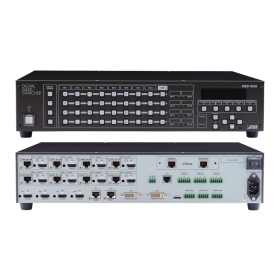
MSD-62 Series User’s Guide 2 Included items Ensure that all items illustrated below are included in the package. If any items are missing or damaged, please contact IDK. One (1) main unit (Figure: MSD-6208) One (1) power cord, 5.9 ft. (1.8 m) -
Page 14: Product Outline
For long reach mode, video signals up to 1080p (24 bit) can be transmitted to 492 ft. (150 m) at maximum if the MSD is used with IDK’s HDBaseT transmitter or receiver that supports 328 ft. (100 m) extension. Dante output is optional. -
Page 15: Features
*1 For long reach mode, video signals up to 1080p (24 bit) can be transmitted to 492 ft. (150 m) at maximum if the MSD is used with IDK’s HDBaseT transmitter or receiver that supports 328 ft. (100 m) extension. -
Page 16: Panels
MSD-62 Series User’s Guide 5 Panels Front panel ④ ⑨ ⑤ ② ③ ⑪ ① ⑦ ⑧ ⑩ ⑫ ⑥ [Fig. 5.1] Front panel drawing (MSD-6208) [Table 5.1] Front panel features Feature Description ① Standby switch Standby or turns on the MSD. 【See: 8.1 Main power switch and standby key】... -
Page 17: Rear Panel
MSD-62 Series User’s Guide Rear panel ⑪ ⑩ ⑦ ⑬ ⑧ ⑫ ① ⑤ ② ③ ⑭ ⑥ ⑮ ④ ⑨ ⑯ [Fig. 5.2] Rear panel drawing (MSD-6208 with Dante) [Table 5.2] Rear panel features Feature Description ① Main POWER switch Controls the main power of the MSD. - Page 18 MSD-62 Series User’s Guide [Table 5.3] Rear panel features (Cont’d) Feature Description ⑦ HDMI output connectors Output connectors for HDMI and DVI signal, interfaces with sink devices such as LC monitors and projectors. 【See: 9.9.8 Output connector】 ⑧ HDBaseT output Output connector for HDBaseT signal connectors Connects to a receiver over a twisted pair cable.
-
Page 19: System Configuration Example
For long reach mode, video signals up to 1080p (24 bit) can be transmitted to 492 ft. (150 m) at maximum if the MSD is used with IDK’s HDBaseT transmitter or receiver that supports 328 ft. (100 m) extension. [Fig. 6.1] Normal mode (MSD-6208) - Page 20 For long reach mode, video signals up to 1080p (24 bit) can be transmitted to 492 ft. (150 m) at maximum if the MSD is used with IDK’s HDBaseT transmitter or receiver that supports 328 ft. (100 m) extension. [Fig. 6.2] Image combination mode (MSD-6208)
- Page 21 MSD-62 Series User’s Guide <4K mode: 4K Video> 4K@30 4K@30 4K@30 4K@30 4K monitor 4K monitor 4K monitor 4K monitor OUT5 OUT6 OUT7 OUT8 4K@30 4K@30 4K@30 4K@30 HDMI / DVI Up to 98 ft. (30 m) 4K monitor 4K monitor 4K monitor 4K monitor OUT1...
-
Page 22: Precautions
MSD-62 Series User’s Guide 7 Precautions Before connecting to external devices, follow the precautions below. Installation When installing the MSD, please observe the following precautions. ● Do not stack or place one MSD directly on top of another MSD. ● Do not block vent holes. To provide adequate ventilation, maintain sufficient clearances around the MSD (30 mm/1.18 inches or more). -
Page 23: Cabling
MSD-62 Series User’s Guide Cabling When connecting the MSD to external devices, please observe the following precautions. ・Read manuals for the external devices. ・ Before you connecting cables to the MSD or an external device, dissipate static electricity by touching grounded metal such as racks before handling signal cables. -
Page 24: Cables
MSD-62 Series User’s Guide 7.2.1 Cables Use the correct HDMI cable or HDMI-DVI conversion cable depending on the system configuration. For analog audio and RS-232C, select or fabricate cables to match the connectors as needed. 7.2.2 DVI-I input connector Female 29-pin DVI-I connectors are used for DVI inputs. The DVI-I input connectors can be used for HDMI/DVI digital signals and for analog signals. - Page 25 MSD-62 Series User’s Guide 11 12 15 16 23 24 [Fig. 7.3] Female 29-pin DVI-I connector [Table 7.1] Pin assignments Input signal Pin # HDMI / DVI Analog RGB Analog YPbPr Composite video TMDS Data2- N.C. N.C. N.C. N.C. TMDS Data2+ N.C.
-
Page 26: Twisted Pair Cable For Extension
MSD-62 Series User’s Guide 7.2.3 Twisted pair cable for extension To ensure the best performance of twisted pair cables, select a correct twisted pair cable and connect it correctly. ● Cat5e UTP/STP and Cat6 UTP/STP can be used, but we recommend CAT.5E HDC cable* for optimal performance. -
Page 27: Connecting Audio Cable
MSD-62 Series User’s Guide 7.2.4 Connecting audio cable The MSD’s audio input and output connectors are for 5-pin terminal block. Connect audio cables to the 5-pin terminal block. The MSD supports both balanced and unbalanced analog signals. AWG28 to AWG16 conductor gauge is recommended. The recommended wire strip length is 0.28 in. (7 mm). Up to 0.28"... -
Page 28: Contact Closure
MSD-62 Series User’s Guide 7.2.6 Contact closure The MSD has a total of nine (9) independently controlled contact closure channels for external control. Each connector supports three (3) channels. The maximum load for each contact is 24 VDC @ 500 mA. Connect a cable to the 6-pin terminal block, and then insert into the appropriate connector on the MSD’s rear panel. -
Page 29: Basic Operation
MSD-62 Series User’s Guide 8 Basic Operation Main power switch and standby key The rear panel has the main power switch while the front panel includes the standby key. The power LED of the front panel shows the device’s power status. [Table 8.1] Power status Status Main power switch... -
Page 30: Selecting Input Channels
Outputting IN4 input signal to OUT2 Outputting IN7 input signal to OUT3 [Fig. 8.1] Cross-point indication (MSD-6203) For MSD-6206 or MSD-6208, use output channel switching keys to select the target output channels. Outputting IN1 input signal to OUT1 Outputting IN3 input... -
Page 31: Video Processing Mode
Up to four windows can be combined and output as one output video. For MSD-6203 and MSD-6204, the same video is output from each output channel. For MSD-6206, the same video is output OUT1, OUT2, OUT3, and OUT4; another video is output to OUT5 and OUT6. - Page 32 MSD-62 Series User’s Guide Full HD Full HD Full HD Full HD Monitor Monitor Monitor Monitor OUT1 OUT2 OUT3 OUT4 HDMI / DVI Up to 141 ft. (40 m) [Fig. 8.4] Video combination mode (MSD-6204 with Dante) Full HD Full HD Monitor Monitor OUT5...
- Page 33 [Fig. 8.6] Video combination mode (MSD-6208 with Dante) ■ Window settings for MSD-6203 and MSD-6206: For MSD-6203, you can switch input channel of Window4 from the menu, a WEB browser, or communication commands. For MSD-6206, you can switch input channel of Window7 and Window8 from the menu, a WEB browser, or communication commands.
- Page 34 MSD-62 Series User’s Guide ■ Window display priority When a window is on another window, the overlapped area having a higher priority will be displayed. 【See: 9.5.3 Window display priority】 ■ Hiding window You can set all windows to be displayed or un-displayed separately. If changing the number of windows, set “9.5.5 Window”...
-
Page 35: Mode
Video and audio of the selected input channel are output to output channels as follows. [Table 8.3] Same signal is output to the following groups Model Group MSD-6203 Group1: OUT1 and OUT2 Group2: OUT3 MSD-6204 Group1: OUT1 and OUT2 Group2: OUT3 and OUT4... - Page 36 OUT1 OUT2 OUT3 HDMI / DVI 98 ft. (30 m) Up to 4K@30 Up to 4K@30 [Fig. 8.9] Video output with 4K mode (MSD-6203 with Dante) Tip: 4K@30 video is output from OUT3 (MSD-6203). 4K@30 4K@30 4K@30 4K@30 4K monitor...
- Page 37 MSD-62 Series User’s Guide 4K@30 4K@30 4K monitor 4K monitor OUT5 OUT6 4K@30 4K@30 4K@30 4K@30 HDMI / DVI Up to 98 ft. (30 m) 4K monitor 4K monitor 4K monitor 4K monitor OUT1 OUT2 OUT3 OUT4 HDMI / DVI Up to 98 ft.
- Page 38 MSD-62 Series User’s Guide 4K@30 4K@30 4K@30 4K@30 4K monitor 4K monitor 4K monitor 4K monitor OUT5 OUT6 OUT7 OUT8 4K@30 4K@30 4K@30 4K@30 HDMI / DVI Up to 98 ft. (30 m) 4K monitor 4K monitor 4K monitor 4K monitor OUT1 OUT2 OUT3...
-
Page 39: Menu Operation
MSD-62 Series User’s Guide Menu operation You can use the VFD screen and front panel keys to view and control settings. Press the “MENU/SET” key to apply settings and to change the menu level. Press the “ESC” key to go back to the previous screen. Use the “▲”... -
Page 40: Sink Device Power Control
MSD-62 Series User’s Guide Sink device power control You can register control commands to power the sink device on/off. By pressing the appropriate key, control commands are sent to the sink device. The DISPLAY POWER key illuminates when the sink device is powered on. The key does not illuminate when the sink device is powered off. -
Page 41: Locking And Unlocking Key Function
MSD-62 Series User’s Guide Locking and unlocking key function Press and hold the “ESC” key for two seconds or longer to set/cancel keylock for keys below. You will hear a beep tone and then one of the following messages is displayed for 1 second. You can group target keys. -
Page 42: Dante Output (Optional)
MSD-62 Series User’s Guide Dante output (Optional) Dante (Digital Audio Network Through Ethernet) is an audio networking technology developed by Audinate. The MSD converts digital and analog audio into Dante format with 48-kHz sampling frequency and 24-bit sample size. Up to 64 channels can be output. Multi channel PCM output is assigned to Dante output channel. However, Dante output channels 61 to 64 channels can be selected from digital audio input or analog audio input. -
Page 43: Ip Network Connection
MSD-62 Series User’s Guide 8.8.1 IP network connection Redundant connection and Daisy chain connection (Redundant connection is set by default) are supported for devices with Dante. The IP address for Dante connectors (Primary and Secondary) is automatically obtained over IP network. Use a Cat5e or better cable for Dante. -
Page 44: Dante Controller
MSD-62 Series User’s Guide Speaker Analog audio Power amplifier (Dante supported Laptop Mixture (Dante supported) Laptop Primary Secondary connector Secondary Primary connector connector connector Dante connector Dante connector (Primary) (Secondary) HDMI Digital audio Analog audio HDBaseT Laptop Digital audio HDMI HDMI Digital audio Digital audio... -
Page 45: Initialization
MSD-62 Series User’s Guide Initialization All settings will be reset to factory default values by powering on the MSD while pressing the “ESC” key. Press and hold the “ESC” key until you hear a long beep sound. Table 8.4 below, shows the Factory default values. When settings are initialized from the WEB browser, they can be initialized without changing LAN settings. - Page 46 MSD-62 Series User’s Guide [Table 8.6] Factory default (Cont’d) Menu Factory default OUTPUT TIMING RESOLUTION Each output channel P.66 Default AUTO MONITOR ASPECT Each output channel P.67 Default RESOLUTION INPUT ASPECT Each input channel, each input signal P.67 Default AUTO-1 ASPECT PROCESS Each input channel, each input signal P.68...
- Page 47 MSD-62 Series User’s Guide [Table 8.7] Factory default (Cont’d) Menu Factory default VIDEO FUNCTION MODE SELECT P.72 Default WINDOW INPUT CH Each window P.72 Default WINDOW PRIORITY Each window P.73 Default WINDOW1, 5: Priority1 (high) WINDOW2, 6: Priority 2 WINDOW3, 7: Priority 3 WINDOW4, 8: Priority 4 (low) WINDOW FLIP H Each window...
- Page 48 MSD-62 Series User’s Guide [Table 8.8] Factory default (Cont’d) Menu Factory default IMAGE EFFECT INPUT SHARPNESS Each input channel, each input signal P.75 Default INPUT BRIGHTNESS Each input channel, each input signal P.75 Default 100 % INPUT CONTRAST Each input channel, each input signal P.75 Default R : 100 %...
- Page 49 MSD-62 Series User’s Guide [Table 8.9] Factory default (Cont’d) Menu Factory default INPUT SETTING INPUT VIDEO DETECT Each input channel, digital input only P.78 Default 10000 ms HDCP INPUT ENABLE Each input channel, digital input only P.79 Default HDCP 1.4 ANALOG INPUT TYPE Each input channel, each input signal, analog input only P.80...
- Page 50 MSD-62 Series User’s Guide [Table 8.10] Factory default (Cont’d) Menu Factory default INPUT TIMING AUTO SETUP Each input channel, each input signal, analog input only P.84 Default NORMAL MODE H TOTAL DOTS Each input channel, each input signal, analog input only P.86 Default Depends on input signal...
- Page 51 MSD-62 Series User’s Guide [Table 8.11] Factory default (Cont’d) Menu Factory default OUTPUT SETTING OUTPUT EQUALIZER Each output channel P.90 Default OUTPUT MODE Each output channel P.90 Default HDMI YCbCr 4:4:4 MODE SYNC OUTPUT Each output channel P.91 Default VIDEO OUTPUT Each output channel P.91 Default...
- Page 52 MSD-62 Series User’s Guide [Table 8.12] Factory default (Cont’d) Menu Factory default AUDIO OUTPUT LEVEL Each output channel P.100 Default 0 dB OUTPUT MUTE Each output channel P.100 Default AUDIO INPUT SELECT Each input channel, digital input only P.100 Default AUTO INPUT OFFSET Each input channel, each input signal...
- Page 53 MSD-62 Series User’s Guide [Table 8.13] Factory default (Cont’d) Menu Factory default EDID EDID DATA Each input channel, digital input only P.104 Default INTERNAL EDID PC RESOLUTION Each input channel P.105 Default 1080p(1920x1080) AV RESOLUTION Each input channel, digital input only P.107 Default AUTO...
- Page 54 MSD-62 Series User’s Guide [Table 8.14] Factory default (Cont’d) Menu Factory default COM PORT PARAMETERS RS-232C channel P.111 Default Baud rate : 9600 Data bit length Parity check : NONE Stop bit FUNCTION RS-232C channel P.111 FORWARDING RS-232C channel P.112 Default FWD TX CH Each output channel(OUT1B to OUT8B)
- Page 55 MSD-62 Series User’s Guide [Table 8.15] Factory default (Cont’d) Menu Factory default PRESET COMMAND COMMAND EDIT Each control command P.118 Default [Table 9.22] Setting control command RECV COMMAND EDIT Each reply command P.123 Default [Table 9.27] Setting reply command COMMAND LINK Each control command execution condition P.126 Default...
- Page 56 MSD-62 Series User’s Guide [Table 8.16] Factory default (Cont’d) Menu Factory default BITMAP BITMAP OUTPUT Each output channel P.137 Default BACKGROUND COLOR Each output channel, each bitmap P.137 Default R : 255 G : 255 B : 255 ASPECT Each output channel, each bitmap P.137 Default AUTO...
- Page 57 MSD-62 Series User’s Guide [Table 8.17] Factory default (Cont’d) Menu Factory default OTHERS OP LOCK MODE CHANNEL P.147 MENU PRESET LOAD COMMAND DISPLAY POW OUTPUT CHANNEL SELECT Default LOCK BUZZER P.148 Default COMMAND AUTO LOCK P.148 Default POWER SAVE P.148 Default DISP POW BUTTON ON P.149...
- Page 58 Can be set for each LAN connection Each 2 HDBaseT output Can be set for each 2 HDBaseT output channels channels MSD-6203: OUT1/OUT2, and OUT3 MSD-6204: OUT1/OUT2 and OUT3/OUT4 MSD-6206: OUT1/ OUT2, OUT3/OUT4, and OUT5/OUT6 MSD-6208: OUT1/OUT2, OUT3/OUT4, OUT5/OUT6, and OUT7/OUT8...
-
Page 59: Control From Web Browser
MSD-62 Series User’s Guide 8.10 Control from WEB browser To control the MSD from a WEB browser, enter the IP address that is programmed into the MSD in the address bar of the WEB browser to display the WEB menu. Note that the default IP address for all MSD switching devices is: 192.168.1.199 【See: 9.13.1 IP address/Subnet mask/Gateway address】... -
Page 60: Menu
│/*9.6Quality setting*/ │ ├─Sub menu ├─IMAGE EFFECT │ ├ │ ├─INPUT SHARPNESS │ ├─INPUT BRIGHTNESS │ ├─INPUT CONTRAST MSD-6208, MSD-6206, MSD-6204, MSD-6203 │ │ ├─INPUT HUE │/*9.3 Operation from front panel*/ │ ├─INPUT SATURATION ├─FRONT OPERATION │ ├─INPUT SETUP LEVEL │... - Page 61 MSD-62 Series User’s Guide │/*9.9 Output settings*/ │/*9.12 RS-232C*/ ├─OUTPUT SETTING ├─COM PORT │ ├─OUTPUT EQUALIZER │ ├─PARAMETERS │ ├─OUTPUT MODE │ ├─FUNCTION │ ├─SYNC OUTPUT │ ├─FORWARDING │ ├─VIDEO OUTPUT │ ├─FWD TX CH │ ├─VIDEO SWITCHING │ └─FWD RX CH │...
- Page 62 MSD-62 Series User’s Guide │/*9.17 Startup setting*/ ├─POWER ON SETTING │ ├─POWER SWITCH │ ├─DISPLAY POWER │ ├─COMMAND/PRESET │ └─OPERATION LOCK │ │/*9.18 Other settings*/ ├─OTHERS │ ├─OP LOCK MODE │ ├─BUZZER │ ├─COMMAND AUTO LOCK │ ├─POWER SAVE │ ├─DISP POW BUTTON ON │...
-
Page 63: Input Signal Automatic Detection
MSD-62 Series User’s Guide Input signal automatic detection The MSD continuously monitors its input signals. If a particular signal has previously been connected to the MSD’s input, the output signal will be presented in the same format as it was during the most recent session. If an input signal does not match any signal previously presented to the MSD, only the input timing settings are automatically negotiated. - Page 64 MSD-62 Series User’s Guide The following attributes are saved for each input signal. [Table 9.1] Attributes saved for each input signal Setting Attribute Setting position, size, and Aspect ratio, Aspect ratio control, Overscan, masking Display position, Display size, Masking Quality setting Sharpness, Brightness, Contrast, HUE, Saturation, Black level Input settings Analog input signal parameters...
-
Page 65: Operation From Front Panel
MSD-62 Series User’s Guide Operation from front panel You can set the operation mode: Channel switching mode and control command execution key. 9.3.1 Channel switching mode Menu Top→FRONT OPERATION→SWITCHING MODE Setting value V&A [Default], VIDEO, AUDIO Video and audio signals can be switched simultaneously or separately. Select a switching mode in this menu first and then switch the desired signals by pressing the front keys. -
Page 66: Setting Position, Size, And Masking
MSD-62 Series User’s Guide Setting position, size, and masking Position, size, and masking attributes can be set for both the input ports and output ports of the MSD. Normally, it is preferable to set them for the input ports. If edges are cut off due to enlarged display area by the sink device side or if it is desired to modify the displayed area for all inputs at once, set the desired attributes for the output ports. -
Page 67: Aspect Ratio For Sink Device
MSD-62 Series User’s Guide 9.4.2 Aspect ratio for sink device Menu Top→OUTPUT TIMING→MONITOR ASPECT Setting for Each output channel Setting value ・RESOLUTION ・4:3 ・5:4 ・5:3 [Default] ・16:9 ・16:10 ・256:135 You can set the aspect ratio of the connected sink device. If you select “RESOLUTION,”... -
Page 68: Aspect Ratio Control
MSD-62 Series User’s Guide 9.4.4 Aspect ratio control Menu Top→OUTPUT TIMING→ASPECT PROCESS Setting for Each input channel, each input signal Setting value L-BOX/S-PANEL : Letter box/side panel [Default] S-CUT/TB-CUT : Side cut/top bottom cut Below is a visual description of restoring aspect ratio: Output signal Input signal L-BOX/S-PANEL... -
Page 69: Display Size
MSD-62 Series User’s Guide 9.4.7 Display size Menu Top→OUTPUT TIMING→INPUT SIZE (input side) / OUTPUT SIZE (output side) Setting for Input side : Each input channel, each input signal Output side : Each output channel (Common to OUTA / OUTB) Setting value Input side: Horizontal size (Horizontal output resolution ÷... -
Page 70: Masking
MSD-62 Series User’s Guide 9.4.8 Masking Menu Top→OUTPUT TIMING→INPUT MASKING (Input side) / OUTPUT MASKING (output side) Setting for Input side : Each input channel, each input signal Output side : Each output channel Setting value Input side: Left side masking (Horizontal input position to Right side masking [Default] 0) Right side masking... -
Page 71: Background Color
MSD-62 Series User’s Guide 9.4.10 Background color Menu Top→OUTPUT TIMING→BACKGROUND COLOR Setting for Each output channel Setting for R / G / B:0 to 255 [Default] R / G / B: 0 (black) You can set the background color of output video. If you set “LINK”... -
Page 72: Video Processing Setting
MSD-62 Series User’s Guide Video processing setting Three video output modes are available. 9.5.1 Video output mode Menu Top→VIDEO FUNCTION→MODE SELECT Setting for : Normal mode [Default] OVERLAY : Video combination mode 4K MODE :4K mode (Up to 4K@30) You can set the video processing mode. 【See: 8.3.1 Normal mode】... -
Page 73: Window Display Priority [Overlay Mode]
MSD-62 Series User’s Guide 9.5.3 Window display priority [OVERLAY mode] Menu Top→VIDEO FUNCTION→WINDOW PRIORITY Setting for Each window Setting value [Table 9.4] Window priority setting [Table 9.4] Window priority setting Item Value Window 1 to 8 Priority (PRI) 1 (Highest) to 4 (Lowest) If some or all windows are overlapped, windows are displayed according to the window priority setting as follows. -
Page 74: Horizontal Flip [Off / Overlay Mode]
MSD-62 Series User’s Guide 9.5.4 Horizontal flip [OFF / OVERLAY mode] Menu Top→VIDEO FUNCTION→WINDOW FLIP H Setting for Each window Setting value OFF : Does not flip [Default] ON : Flips horizontally Flips [Fig. 9.9] Flip horizontally Note: This feature is only for OFF mode and video combination mode (OVERLAY). 9.5.5 Window hiding Menu Top→VIDEO FUNCTION→WINDOW INVISIBLE... -
Page 75: Quality Setting
MSD-62 Series User’s Guide Quality setting Setting items for input channels are for correcting color bias. Image quality to be output can be set for each input side (input channels) and output side (output channels) as follows. Setting for each input channel Setting for each output channel SATURATION BRIGHTNESS... -
Page 76: Hue
MSD-62 Series User’s Guide 9.6.4 HUE Menu Top→IMAGE EFFECT→INPUT HUE Setting for Each input channel, each input signal Setting value 0°to 359° [Default]0° You can set the color HUE for each input signal. Note: It can be set up to 359°. However, if the dot clock of input signal exceeds 165 MHz, it is set to 0° automatically. -
Page 77: Default Color
MSD-62 Series User’s Guide 9.6.8 Default color Menu Top→IMAGE EFFECT→IN DEFAULT COLOR (Input side) / OUT DEFAULT COLOR (Output side) Setting for Input side :Each input channel, each input signal Output side :Each output channel You can initialize settings of the following items. A long buzzer tone will sound when the initialization is completed by pressing the MENU/SET key. -
Page 78: Input Settings
MSD-62 Series User’s Guide Input settings 9.7.1 No-signal input monitoring Menu Top→INPUT SETTING→INPUT VIDEO DETECT Setting for Each input channel, digital input only Setting value OFF, 2000ms to 15000ms (100mssteps) [Default] 10000ms If you change the EDID settings of the MSD or power the MSD off/on, the source device may not output a video signal. -
Page 79: Hdcp Input Setting
MSD-62 Series User’s Guide 9.7.2 HDCP input setting Menu Top→INPUT SETTING→HDCP INPUT ENABLE Setting for Each input channel, digital input only Setting value HDCP1.4 : Supports HDCP 1.4 [Default] DISABLE : Not support HDCP Some source devices negotiate with the connected device to determine if it supports HDCP encryption. After this negotiation, the source device decides whether they encrypt HDCP signal or not. -
Page 80: Analog Input Signal Parameters
MSD-62 Series User’s Guide 9.7.3 Analog input signal parameters Menu Top→INPUT SETTING→ANALOG INPUT TYPE Setting for Each input channel, each input signal, analog input only Setting value ・AUTO : Automatic [Default] ・VIDEO AUTO : Video (Automatic) ・RGB ・VIDEO : Analog RGB : Composite video ・YPbPr : Analog YPbPr ・Y/C... -
Page 81: Automatic Detection Of Video Input Interruption
You can enable / disable long reach mode for HDBaseT input. With long reach mode, up to 1080p (24 bit)/ dot clock 148 MHz is supported when using with IDK’s HDbaseT product. Set the MSD’s EDID to 1080p or less or set the connected device’s output to a supported signal format. -
Page 82: Fixing Settings For Each Input Signal
MSD-62 Series User’s Guide 9.7.7 Fixing settings for each input signal Menu Top→INPUT SETTING→INPUT TABLE FIXED Setting for Each input channel Setting value Setting mode: ・SELECTED : Sets for each item [Default] ・ALL FIXED : Does not load settings saved for each input signal but fixes the current settings Individual setting (if “SELECTED”... -
Page 83: Setting Input Timing
MSD-62 Series User’s Guide Setting input timing You can set the timing parameters for analog signal inputs. The MSD recalls the optimal table from its built-in library of tables and adjusts the input timing automatically, you typically will not need to change settings in this menu. However, if signals which are not registered in the MSD tables are input or if part of the video image is cut off while relying on the standard table registered in the MSD, you may optimize the input timing parameters manually. -
Page 84: Automatic Measurement
MSD-62 Series User’s Guide 9.8.1 Automatic measurement Menu Top→INPUT TIMING→AUTO SETUP Setting for Each input channel, each input signal, analog input only Setting value ・NORMAL MODE ・4:3 ・5:3 ・16:10 [Default] ・NEXT ASPECT ・5:4 ・16:9 Analog RGB/analog YPbPr input video is measured to set “9.8.2 The total number of horizontal dots”, “9.8.3 Start position”, “9.8.4 Active area”, and “9.8.9 Tracking”... - Page 85 MSD-62 Series User’s Guide If only start position is changed, “NORMAL END” is displayed. If active area is changed if “NORMAL MODE” is selected or if “NEXT ASPECT” or aspect ratio is specified directly, the set resolution is displayed. [IN8 AUTO SETUP] 1024x 768 60.00Hz If there is no input signal on the input channel it shows “NOT AVAILABLE NOW”...
-
Page 86: The Total Number Of Horizontal Dots
MSD-62 Series User’s Guide 9.8.2 The total number of horizontal dots Menu Top→INPUT TIMING→H TOTAL DOTS Setting for Each input channel, each input signal, analog input only Setting value 400DOT to 4125DOT [Default] varies depending on the input signal You can set the total number of horizontal dots of analog RGB/analog YPbPr input video. The settable values vary depending on the input signal. -
Page 87: Active Area
MSD-62 Series User’s Guide 9.8.4 Active area Menu Top→INPUT TIMING→H DISPLAY (Horizontal) / V DISPLAY (Vertical) Setting for Each input channel, each input signal Setting value [Table 9.9] Settings of active area [Table 9.10] Settings of active area Function Setting value Horizontal active area 64DOT to 2900DOT (The total number of horizontal dots-64 or less) Vertical active area... -
Page 88: Automatic Measurement Of Start Position
MSD-62 Series User’s Guide 9.8.5 Automatic measurement of start position Menu Top→INPUT TIMING→AUTO START POS Setting for Each input channel, each input signal, analog input only Setting value ALL OFF : not measuring all inputs from the input automatically : not measuring the current input signal automatically : measuring the current input signal automatically [Default] The MSD monitors continuously the upper left of analog input video signal and it automatically matches the upper left of the input video and the upper left of the screen. -
Page 89: Loading Device Data
MSD-62 Series User’s Guide 9.8.7 Loading device data Menu Top→INPUT TIMING→LOAD Setting for Each input channel, each input signal Device data with input timing can be loaded according to the input signal. Press the MENU/SET key to apply the setting. If there is no input signal on the input channel it shows “NOT AVAILABLE NOW”... -
Page 90: Output Settings
Cable length Shorter than 33 ft. (10 m) 33 ft. (10 m) or longer Setting OFF to MIDDLE LOW to HIGH Tip: IDK’s cable (AWG24) was used 9.9.2 Output mode Menu Top→OUTPUT SETTING→OUTPUT MODE Setting for Each output channel Setting value ・HDMI YCbCr 4:4:4 MODE [Default]... -
Page 91: Synchronous Signal Output With No Input Video
MSD-62 Series User’s Guide 9.9.3 Synchronous signal output with no input video Menu Top→OUTPUT SETTING→SYNC OUTPUT Setting for Each output channel Setting value ON [Default], OFF You can set whether synchronous signal is output at all times or not. If you set this menu to “ON”, you can prevent the sink device from being switched to the standby mode. Note: In “video combination”... -
Page 92: Window Transaction Effect
MSD-62 Series User’s Guide 9.9.5 Window transaction effect Menu Top→OUTPUT SETTING→VIDEO SWITCHING Setting for Each output channel Setting value ・FREEZE→FADE OUT-IN ・BOTTOM→TOP WIPE [Default] ・FADE OUT-IN ・TOP→BOTTOM WIPE ・CUT ・RIGHT→LEFT WIPE ・LEFT→RIGHT WIPE You can select a window transition effect for when the video inputs is switched. If “9.7.4 Automatic detection of video input interruption"... -
Page 93: Output Connector
MSD-62 Series User’s Guide 9.9.8 Output connector Menu Top→OUTPUT SETTING→OUTPUT CONNECTOR Setting for Each output channel Setting value HDMI [Default], HDBaseT The MSD outputs video to the HDMI output or HDBaseT output. You can set a desired connector. 9.9.9 HDCP output Menu Top→OUTPUT SETTING→HDCP OUTPUT MODE Setting for... -
Page 94: The Number Of Hdcp Retries
MSD-62 Series User’s Guide 9.9.10 The number of HDCP retries Menu Top→OUTPUT SETTING→HDCP ERROR RETRY Setting for Each output channel Setting value ETERNITY : retries until succeed [Default] 0 to 100 :0 to 100times You can set the number of HDCP retries. If an HDCP-compliant sink device is connected and you set “HDCP”... -
Page 95: Cec Connection
MSD-62 Series User’s Guide 9.9.12 CEC connection Menu Top→OUTPUT SETTING→CEC CONNECTION Setting for Each output channel Setting value ・NOT CONNECTED [Default] ・SELECTED CHANNEL ・IN1 to IN6 You can set the CEC connection for when CEC-supported device is connected to HDMI input connector. Press the MENU/SET key to apply the setting. -
Page 96: Priority Of Input Channel Automatic Switching
MSD-62 Series User’s Guide 9.9.14 Priority of input channel automatic switching Menu Top→OUTPUT SETTING→AUTO SWITCHING ON / AUTO SWITCHING OFF Setting for Each output channel Setting value [Table 9.13] Setting of priority of input channel automatic switching [Table 9.13] Setting of priority of input channel automatic switching Item Set value Default... - Page 97 MSD-62 Series User’s Guide ■AUTO SWITCHING OFF: Selects other input channel when the input signal of currently-selected channel changes from “ON” to “OFF”. The MSD switches input signal automatically as follows: ・Switches to the input channel having input signal and highest priority. ・If some channels have the same priority, the MSD switches to the lower input channel having input signal.
-
Page 98: Ignoring Duration After Automatic Switching
OFF : Long reach mode OFF Up to 328 ft. (100 m) [Default] You can enable / disable HDBaseT output long reach mode. Long reach mode: Up to 1080p (24 bit)/ dot clock 148 MHz is supported when using with IDK’s HDbaseT product. Select a supported output format. -
Page 99: Audio Setting
MSD-62 Series User’s Guide 9.10 Audio setting HDMI digital audio supports formats mentioned in the table below. Set the audio depending on device connected to the HDMI output connector. Only “2 channel linear PCM” can be input by default. If you want to use “Multi channel linear PCM” or bit stream signal, set “Audio format”... -
Page 100: Output Level
MSD-62 Series User’s Guide 9.10.1 Output level Menu Top→AUDIO→OUTPUT LEVEL Setting for Each output channel Setting value -60dB to 10dB [Default] 0dB You can set the audio output level. If you change the output level while audio output mute is set to “ON”, it will be unmuted. If you set “9.18.8 Top page”... -
Page 101: Lip Sync
MSD-62 Series User’s Guide 9.10.5 Lip sync Menu Top→AUDIO→OUTPUT LIP SYNC (Output side) / INPUT LIP SYNC (Input side) Setting for Output side: Each output channel Input side: Each input channel, each input signal Setting value 0FRAME to 8FRAME [Default]0FRAME You can adjust the gap between video (motion) and audio (sound). -
Page 102: Analog Audio Output Connector
MSD-62 Series User’s Guide 9.10.7 Analog audio output connector Menu Top→AUDIO→ANALOG OUTPUT Setting for Each output channel Setting value ・OUT1 : Outputs audio of output channel1 to the analog audio output connector. [Default] ・OUT2 : Outputs audio of output channel2 to the analog audio output connector. ・OUT3 : Outputs audio of output channel3 to the analog audio output connector. -
Page 103: Test Tone
MSD-62 Series User’s Guide 9.10.9 Test tone Menu Top→AUDIO→TEST TONE Setting for Each output channel Setting value Test tone: [Default] 1kHz, 400Hz Speaker: ・ALL ・LOW FREQUENCY EFFECT [Default] ・FRONT L/R ・FRONT CENTER ・REAR L/R ・REAR LEFT ・REAR L/R CENTER ・REAR RIGHT ・FRONT LEFT ・REAR LEFT CENTER ・FRONT RIGHT... -
Page 104: Edid (Extended Display Identification Data)
MSD-62 Series User’s Guide 9.11 EDID (Extended Display Identification Data) You can set or customize EDID to be sent to the source device. Change the setting as needed. ■ Setting EDID Step 1: If you use copied EDID, copy the target EDID from the sink device. Step 2: Set the EDID that will be sent to the source device. -
Page 105: Resolutions For Pcs
MSD-62 Series User’s Guide 9.11.2 Resolutions for PCs Menu Top→EDID→PC RESOLUTION Setting for Each input channel Setting value ・SVGA(800x600) ・WXGA(1366x768) ・WUXGA(1920x1200) ・XGA(1024x768) ・SXGA+(1400x1050) ・QWXGA(2048x1152) ・720p(1280x720) ・WXGA+(1440x900) ・WQHD(2560X1440) ・WXGA(1280x768) ・WXGA++(1600x900) ・WQXGA(2560x1600) ・WXGA(1280x800) ・UXGA(1600x1200) ・2160p@30 (3840x2160) ・Quad-VGA(1280x960) ・WSXGA+(1680x1050) ・SXGA(1280x1024) ・1080i(1920x1080) ・WXGA(1360x768) ・1080p(1920x1080) [Default]IN1 to IN8 : 1080p(1920x1080) You can set the resolution requested to be output from the source device. - Page 106 MSD-62 Series User’s Guide [Table 9.16] Supported resolution Supported resolution Input resolution setting 800x600 1024x768 1280x720[D4] 1280x768 1280x800 1280x960 1280x1024 1360x768 1366x768 1400x1050 1440x900 1600x900 1600x1200 1680x1050 1920x1080i[D3] 1920x1080p[D5] 1920x1200 2048x1152 2560x1440 2560x1600 2160p (30p) Y: Supported , N: Not supported...
-
Page 107: Input Resolution For Av Devices
MSD-62 Series User’s Guide 9.11.3 Input resolution for AV devices Menu Top→EDID→AV RESOLUTION Setting for Each input channel, digital input only Setting value ・AUTO [Default] ・720p ・2160p@30 ・UNUSED ・1080i ・4096x2160@30 ・480p ・1080p You can set the resolution requested to be output from AV devices (such as Blu-ray players). “2160p@30”, “4096x2160@30”: can be selected for IN1, IN5, and IN6. -
Page 108: Deep Color
MSD-62 Series User’s Guide 9.11.4 Deep Color Menu Top→EDID→DEEP COLOR INPUT Setting for Each input channel, digital input only Setting value 24-BIT COLOR [Default] 30-BIT COLOR You can set the color depth to be output from the source device. This menu is valid only if you select “INTERNAL EDID” for “9.11.1 EDID” and you select a resolution other than “UNUSED”... -
Page 109: Speaker Configuration
MSD-62 Series User’s Guide 9.11.6 Speaker configuration Menu Top→EDID→SPEAKER Setting for Each input channel, digital input only Setting value Setting mode: AUTO [Default], MANUAL Each speaker : ON, OFF The number of speakers: 1 to 8 [Table 9.19] Default speaker configuration FLC/ RLC/ FLW/... -
Page 110: Copying Edid
MSD-62 Series User’s Guide You can set the speaker configuration of multi channel audio. This menu is valid only if you select “INTERNAL EDID” for “9.11.1 EDID”, you select a resolution other than “UNUSED” for “9.11.3 Input resolution for AV devices”. If you select “AUTO”... -
Page 111: Rs-232C
MSD-62 Series User’s Guide 9.12 RS-232C The RS-232C connector of the MSD can output communication command control from PCs and control command to external devices from the MSD. The operation mode will be switched according to “9.12.2 RS-232C operation mode”. 【See: 9.14 Setting control command】... -
Page 112: Rs-232C Hdbaset Connection
MSD-62 Series User’s Guide 9.12.3 RS-232C HDBaseT connection Menu Top→COM PORT→FORWARDING Setting for RS-232C channel Setting value OFF [Default], ON You can set the communication between MSD’s RS-232C connector and RS-232C connectors of HDBaseT transmitters or receivers that is connected to HDBaseT I/O connector. If setting this menu to “ON”, RS-232C communication data can be transmitted from a PC that is connected to the RS-232C connector to HDBaseT transmitter (connected to the HDBaseT input connector) and receiver (connected to RS-232C output connector). -
Page 113: Lan
MSD-62 Series User’s Guide 9.13 LAN The internal switching hub enables connections between the MSD’s LAN connector and LAN connectors of twisted pair cable transmitter and receiver that are connected to HDBaseT I/O connectors. Bidirectional communication is also available. Communication command control from PC to the MSD and control command output from the MSD to external devices can be executed from all LAN ports. -
Page 114: Ip Address/Subnet Mask/Gateway Address
MSD-62 Series User’s Guide 9.13.1 IP address/Subnet mask/Gateway address Menu IP address: Top→LAN→IP ADDRESS Subnet mask: Top→LAN→SUBNET MASK Gateway address: Top→LAN→GATEWAY ADDRESS Setting value [Default] IP address: 192.168.1.199 Subnet mask: 255.255.255.0 Gateway address: 192.168.1.200 You can set the IP address, subnet mask, and gateway address. Press the MENU/SET key to apply the setting. -
Page 115: Tcp Port Number
9.13.5 Setting HDBaseT LAN Menu Top→LAN→HDBASET LAN Setting for 2 HDBaseT output channels MSD-6203: OUT1/OUT2, and OUT3 MSD-6204: OUT1/OUT2 and OUT3/OUT4 MSD-6206: OUT1/ OUT2, OUT3/OUT4, and OUT5/OUT6 MSD-6208: OUT1/OUT2, OUT3/OUT4, OUT5/OUT6, and OUT7/OUT8 Setting value ON [Default], OFF You can enable/ disable the LAN of HDBaseT output connector. -
Page 116: Setting Control Command
MSD-62 Series User’s Guide 9.14 Setting control command You can control external devices (for example, turning ON/OFF projectors) via RS-232C, LAN, contact closure, or CEC. You can register up to 32 commands in the MSD. Registered control commands will be associated with control command execution keys (COMMAND A to COMMAND I) or execution conditions such as switching video or audio. - Page 117 MSD-62 Series User’s Guide ■ Control command via RS-232C / LAN communication Control commands can be sent from MSD’s RS-232C connector, LAN connector, or HDBaseT output connector. Before executing control command, set the operation mode of the connector to “TRANSMITTER”. 【See: 9.12.2 RS-232C operation mode】...
-
Page 118: Registering/Editing Control Command
MSD-62 Series User’s Guide 9.14.1 Registering/editing control command Menu Top→PRESET COMMAND→COMMAND EDIT Setting for Each command Setting value [Table 9.23] Setting control command You can register up to 32 control commands and edit them. . Press the MENU/SET key to apply the setting. [Table 9.23] Setting control command Setting item Description... - Page 119 MSD-62 Series User’s Guide [Table 9.24] Setting control command (Cont’d) Setting item Description Range RECV Set whether received data is displayed or OFF [Default] DISPLAY not. ASCII DELIMITER Set the delimiter to be sent at the end of NONE: Not checking delimiter the received data.
- Page 120 MSD-62 Series User’s Guide If you set “RECV DISPLAY” to “OFF”, you cannot set this item. If you set “RECV DISPLAY” to “ASCII” or “HEX”, you cannot set this item. If you set only “LOOP BACK” of communication ports to “ON”, you do not need to set this item. If you set all “RCV CHECK”...
- Page 121 MSD-62 Series User’s Guide [Table 9.25] PJLink command (class1) Command Description R (SP) 0 (CR) Power off (Standby) R (SP) 1 (CR) Power on (Lamp on) R (SP) ? (CR) Get power status T (SP) 1 (CR) Switch input to RGB T (SP) 2 (CR) Switch input to VIDEO T (SP) 3...
- Page 122 MSD-62 Series User’s Guide [Table 9.27] Individual reply command of status acquisition commands Command Description Reply command to power status commands (CR) Stand by (CR) Power ON (CR) Cooling (CR) Warming up Reply command to input status commands (CR) RGB selected (CR) VIDEO selected (CR)
-
Page 123: Registering / Editing Reply Command
MSD-62 Series User’s Guide 9.14.2 Registering / Editing reply command Menu Top→PRESET COMMAND→RECV COMMAND EDIT Setting for Each command Setting value [Table 9.28] Setting reply command You can register up to 32 reply commands and edit them. . Press the MENU/SET key to apply the setting. [Table 9.28] Setting reply command Item Description... - Page 124 MSD-62 Series User’s Guide ■ Setting loop back function If the MSD sends a communication command back to the MSD itself using the loop back function, the MSD replies “OK” if processed normally while it replies “NG” if parameter or command is incorrect. (This differs from reply commands to communication commands received externally;...
- Page 125 MSD-62 Series User’s Guide ■ Mask data Each bit of the received data is ANDed to each bit of mask data, and the result will be compared with the reply command data. Since “FF” is set by factory default, you do not need to change the mask data normally.
-
Page 126: Command Link
MSD-62 Series User’s Guide 9.14.3 Command link Menu Top→PRESET COMMAND→COMMAND LINK Setting for [Table 9.30] Control command execution condition Setting value OFF [Default], COMMAND 1 to COMMAND 32 The MSD has 180 command execution conditions as shown below. If these execution conditions are met, control commands which are associated beforehand will be executed. - Page 127 MSD-62 Series User’s Guide [Table 9.30] Control command execution condition (MSD-6208) Execution condition Function Execution condition Function POWER ON Controlling power COMMAND A to Control command switch COMMAND I, execution key PLANE-A STANDBY COMMAND A to COMMAND I, PLANE-B DISPLAY1 POWER ON Controlling sink device DISPLAY5 POWER ON Controlling sink device...
-
Page 128: Command Execution
MSD-62 Series User’s Guide 9.14.4 Command execution Menu Top→PRESET COMMAND→COMMAND EXECUTION Setting value CMD 1 to CMD 32, COMMAND A ~ COMMAND I You can execute the registered control commands. Only executable control commands are displayed. Press the MENU/SET key to apply the setting. 【See: 9.14.1 Registering/editing control command】... -
Page 129: Command Execution Key: Illuminating Condition
MSD-62 Series User’s Guide 9.14.7 Command execution key: Illuminating condition Menu Top→PRESET COMMAND→COMMAND TALLY Setting for Each control command execution key Setting value REGISTERED : Illuminates if a control command is registered [Default] *1 *2 EXECUTION : Illuminates while a control command is executed If you set “LINK”... -
Page 130: Preset Memory
MSD-62 Series User’s Guide 9.15 Preset memory You can set the cross point memory, preset memory, and start-up memory. 9.15.1 Recalling cross point Menu Top→PRESET MEMORY→LOAD CROSS POINT Setting value No.1 to No.9 You can recall the I/O channel settings saved in the cross point memory. You can also recall settings by pressing control command execution keys (COMMAND A to COMMAND I). -
Page 131: Editing Cross Point
MSD-62 Series User’s Guide 9.15.3 Editing cross point Menu Top→PRESET MEMORY→EDIT CROSS POINT Setting for Each cross point memory Setting value [Table 9.32] Editing cross point [Table 9.32] Editing cross point Setting item Setting value Default Output channel (OUT) 1 to 2 Video input channel (V) --- (Not control), 1 to 8, OFF Audio input channel (A) -
Page 132: Saving All Settings
MSD-62 Series User’s Guide 9.15.5 Saving all settings Menu Top→PRESET MEMORY→SAVE ALL SETTING Setting value No.1 to No.12 You can save up to 12 preset memories and name these memories up to 10 characters from ASCII 20 to 7D. You can skip the naming procedure. Press the MENU/SET key to apply the setting. -
Page 133: Copying Output Setting
MSD-62 Series User’s Guide 9.15.6 Copying output setting Menu Top→PRESET MEMORY→COPY OUTPUT MEMORY Setting value OUT1 to OUT8 → OUT1 to OUT8 You can copy the setting of the selected output channel to other output channels. Press the MENU/SET key to apply the setting. [Table 9.34] Setting to be copied Menu Description... -
Page 134: Start-Up Setting
MSD-62 Series User’s Guide 9.15.7 Start-up setting Menu Top→PRESET MEMORY→STARTUP Setting value [Table 9.35] Start-up setting You can set which settings will be applied at start-up. [Table 9.35] Start-up setting Item Setting value Startup operation Last channel LAST CHANNEL [Default] Starts with the settings last time the MSD powered off. -
Page 135: Bitmap Setting
9.16 Bitmap setting 9.16.1 Sending bitmap file You can set the bitmap image to be displayed on the sink device. Up to four bit maps can be registered. IDK’s logo is displayed by default. Bitmaps can be enlarged but cannot be reduced. The larger the resolution is, the longer the output time will be, and it may take a maximum of approximately six seconds to output a bitmap. - Page 136 MSD-62 Series User’s Guide [Table 9.37] Address input example Control port number of web browser IP address (URL) 80 (Normal) http://192.168.1.199/bitmap.html Other than 80 (5000 to 5999) http://192.168.1.199:5000/bitmap.html (e.g.: 5000) Enter the URL to display the following page. [Fig. 9.30] Bitmap setting page (Example: MSD-6208 with Dante) Once bitmap file is transferred correctly, the message, “BITMAP SAVE NOW PLEASE WAIT”, is displayed.
-
Page 137: Outputting Bitmap Image
MSD-62 Series User’s Guide 9.16.2 Outputting bitmap image Menu Top→BITMAP→BITMAP OUTPUT Setting for Each output channel Setting value OFF [Default] ON (BITMAP1 ON to BITMAP4 ON) You can enable/disable the bitmap image output. If multiple bitmaps are registered, select the bitmap number you want to output. 9.16.3 Background color Menu Top→BITMAP→BACKGROUND COLOR... -
Page 138: Display Position
MSD-62 Series User’s Guide 9.16.5 Display position Menu Top→BITMAP→POSITION Setting for Each output channel, each bitmap Setting value [Fig. 9.32] Position You can set the display position of the bitmap. ● TOP-LEFT ● TOP-RIGHT ● CENTER [Default] ● ● BOTTOM-RIGHT BOTTOM-LEFT [Fig. -
Page 139: Dividing Memory Area
MSD-62 Series User’s Guide 9.16.8 Dividing memory area Menu Top→BITMAP→DIVIDE MEMORY Setting value [Table 9.39] Dividing memory area You can register up to four bitmaps within the available memory area by dividing the memory. You can select one of three dividing modes or specify the size you want to divide manually. Memory areas are controlled by blocks. - Page 140 MSD-62 Series User’s Guide ■ Displaying method “BLOCK” If you select “BLOCK” for “DISPLAY”, the current start and end block positions are displayed on the left of the VFD screen. If a bitmap is registered, the final block position is displayed in parentheses. The start and end block positions after divide are displayed on the right.
-
Page 141: Input Image Capture
MSD-62 Series User’s Guide 9.16.9 Input image capture Menu Top→BITMAP→VIDEO CAPTURE Setting value [Table 9.40] Setting input image capture [Table 9.40] Setting input image capture Setting item Setting value Default Output channel OUT1, OUT2, OUT3, OUT4, OUT1 OUT5, OUT6, OUT7, OUT8 Register number No.1 to No.4 No.1... - Page 142 MSD-62 Series User’s Guide ■ From browser Use a browser (e.g. Microsoft Internet Explorer) to capture input videos and save to the MSD. Enter “/capture.html” after the IP address that is set to the MSD. 【See: 9.13.1 IP address/Subnet mask/Gateway address】 【See: 9.13.3 TCP port number】...
-
Page 143: Startup Setting
MSD-62 Series User’s Guide 9.17 Startup setting 9.17.1 Power state Menu Top→POWER ON SETTING→POWER SWITCH Setting value AUTO [Default], OFF, ON You can set the standby switch state for when the main POWER switch on the rear panel is turned on. 【See: 8.1 Main power switch and standby key】... -
Page 144: Display Power Keys
MSD-62 Series User’s Guide 9.17.2 DISPLAY POWER keys Menu Top→POWER ON SETTING→DISPLAY POWER Setting for Each output channel Setting value AUTO [Default], OFF, ON You can set the DISPLAY POWER key state for when MSD is powered on. “AUTO” : The same state as it was before turning off the MSD or standby. “OFF”... -
Page 145: Control Command Execution Key
MSD-62 Series User’s Guide 9.17.3 Control command execution key Menu Top→POWER ON SETTING→COMMAND/PRESET Setting value AUTO [Default], COMMAND , PRESET LOAD, LOCK You can set the control command execution key state for when MSD is powered on. “AUTO” : The same state as it was before powering off the MSD. “COMMAND”... -
Page 146: Key Function Lock
MSD-62 Series User’s Guide 9.17.4 Key function lock Menu Top→POWER ON SETTING→OPERATION LOCK Setting value AUTO [Default], UNLOCK, LOCK You can set the key function lock for when the MSD is powered on. “AUTO” : The same state as it was before powering off the MSD. “UNLOCK”... -
Page 147: Other Settings
MSD-62 Series User’s Guide 9.18 Other settings 9.18.1 Grouping key function lock Menu Top→OTHERS→OP LOCK MODE Setting for CHANNEL, MENU, PRESET LOAD, COMMAND, DISPLAY POW, OUT CHANNEL SELECT Setting value LOCK [Default], UNLOCK You can group front keys for key function lock. 【See: 8.7 Locking and unlocking key function】... -
Page 148: Beep
MSD-62 Series User’s Guide 9.18.2 Beep Menu Top→OTHERS→BUZZER Setting value ON [Default], OFF You can enable / disable the beep function (sounding every time you press a front panel key). 9.18.3 Automatic lock of control command execution key Menu Top→OTHERS→COMMAND AUTO LOCK Setting value ON [Default], OFF If you select “ON”... -
Page 149: Display Power Key Pressing Duration
MSD-62 Series User’s Guide 9.18.5 DISPLAY POWER key pressing duration Menu Top→OTHERS→DISP POW BUTTON ON Setting value 0ms to 5000ms (by 10 ms) Default 0ms You can set the pressing time of the target DISPLAY POWER key to prevent the sink device from being powered off when the key is pressed accidentally. -
Page 150: Input Channel Automatic Linking
MSD-62 Series User’s Guide 9.18.7 Input channel automatic linking Menu Top→OTHERS→INPUT CHANNEL LINK Setting value VIDEO : OFF [Default], OUT1 to OUT8 AUDIO : OFF [Default], OUT1 to OUT8 The menu pages of each input channel can be displayed by selecting the input number of the menus. With this menu, the menu pages of each input channel can be displayed automatically by switching input in “8.2 Selecting input channels”. -
Page 151: Top Page
MSD-62 Series User’s Guide 9.18.8 Top page Menu Top→OTHERS→TOP DISPLAY Setting value [Fig. 9.38] Top page of VFD screen NORMAL [Default] AUDIO VOLUME MSD-6208 [OUT1 AUDIO] MUTE You can mute/unmute by pressing the “ESC” key. MONITOR STATUS INPUT STATUS (Displaying sink device status) IN1 2 3 4 5 6 7 8 OUT 1 2 3 4 5 6 7 8 [Fig. -
Page 152: Input Signal Status
MSD-62 Series User’s Guide 9.18.9 Input signal status Menu Top→OTHERS→INPUT STATUS Values to be displayed [Table 9.50] Input signal status You can view the input signal status that is input from HDMI and DVI input connectors. [Table 9.50] Input signal status All input channels Video status of each input channel Audio status of each input channel... - Page 153 MSD-62 Series User’s Guide ■ Input video signal format [Table 9.52] Input video signal format Signal type Items to be displayed Example Format type, vertical synchronous 1080p 59.94Hz SDTV / HDTV signal frequency Horizontal / Vertical resolution, vertical 800 x 600 60.00Hz RGB signal synchronous frequency NTSC...
-
Page 154: Sink Device Status
MSD-62 Series User’s Guide 9.18.10 Sink device status Menu Top→OTHERS→MONITOR STATUS Values to be displayed [Table 9.54] Sink device status You can view the status of sink device connected to video output connectors. [Table 9.54] Sink device status All video output connector Each video output connector Display OUT 1 2 3 4 5 6 7 8... - Page 155 MSD-62 Series User’s Guide ■ Error code From the left, statuses of video output, digital audio output, and analog audio output are displayed. (Example: AAA) [Table 9.56] Error code Code Video output Audio output If any number or character is not displayed, video or audio is output correctly. -...
-
Page 156: Viewing Sink Device Edid
MSD-62 Series User’s Guide 9.18.11 Viewing sink device EDID Menu Top→OTHERS→EDID STATUS Values to be displayed [Table 9.57] Sink device EDID You can display EDID information of the sink device that is connected to the video output connector. ・HDMI supported sink device : No.1 to No.5 in the table below ・Non-HDMI-supported sink device : No.1 and No.2 in the table below If no sink device is connected, the VFD screen shows “UNCONNECTED”. -
Page 157: Viewing Version Information
MSD-62 Series User’s Guide 9.18.12 Viewing version information Menu Top→OTHERS→VERSION Values to be displayed Model name and firmware version You can view the model name and firmware version. -
Page 158: Setting Dante (Optional)
MSD-62 Series User’s Guide 9.19 Setting DANTE (Optional) Available only if Dante is mounted. 9.19.1 CH61-CH64 Menu Top→DANTE SETTING→CH61-CH64 Setting value IN8 [Default], AUDIO IN1&2 64 channels are reserved for Dante output. You can select the input audio that is output to Channels 61 to 64. 【See: 8.8 Dante output (Optional)】... -
Page 159: Product Specification
MSD-62 Series User’s Guide 10 Product specification ■ MSD-6203 Item Description 1 input HDMI Deep Color (*1) / DVI 1.0 TMDS single link, HDCP 1.4 TMDS clocks: 25 MHz to 300 MHz, TMDS data rate: 0.75 Gbps to 9 Gbps... - Page 160 For PoH power feeding, please use an HDBaseT transmitter supporting IEEE 802.3af. Use an AWG24 twisted pair cable or thicker cable. RJ-45 (HDBaseT connector) is only for extending digital video and audio signals over a Cat5e / Cat6 twisted pair cable. Use it with IDK’s twisted pair cable transmitter or receiver.
- Page 161 MSD-62 Series User’s Guide *14 For digital systems, some problems, such as an HDCP authentication error, can often be recovered by physically disconnecting and reconnecting the digital cables. However, the Connection Reset feature will fix these problems automatically without the need to physically plug and unplug the cables. It creates the same condition as if the cable were physically disconnected and reconnected.
- Page 162 MSD-62 Series User’s Guide ■ MSD-6204 Item Description 1 input HDMI Deep Color (*1) / DVI 1.0 TMDS single link, HDCP 1.4 TMDS clocks: 25 MHz to 300 MHz, TMDS data rate: 0.75 Gbps to 9 Gbps Built-in cable EQ, EDID emulation Connector: Female HDMI Type A (19-pin) HDMI / DVI 5 inputs...
- Page 163 For PoH power feeding, please use an HDBaseT transmitter supporting IEEE 802.3af. Use an AWG24 twisted pair cable or thicker cable. RJ-45 (HDBaseT connector) is only for extending digital video and audio signals over a Cat5e / Cat6 twisted pair cable. Use it with IDK’s twisted pair cable transmitter or receiver.
- Page 164 MSD-62 Series User’s Guide *14 For digital systems, some problems, such as an HDCP authentication error, can often be recovered by physically disconnecting and reconnecting the digital cables. However, the Connection Reset feature will fix these problems automatically without the need to physically plug and unplug the cables. It creates the same condition as if the cable were physically disconnected and reconnected.
- Page 165 MSD-62 Series User’s Guide ■ MSD-6206 Item Description 1 input HDMI Deep Color (*1) / DVI 1.0 TMDS single link, HDCP 1.4 TMDS clocks: 25 MHz to 300 MHz, TMDS data rate: 0.75 Gbps to 9 Gbps Built-in cable EQ, EDID emulation Connector: Female HDMI Type A (19-pin) HDMI / DVI 5 inputs...
- Page 166 For PoH power feeding, please use an HDBaseT transmitter supporting IEEE 802.3af. Use an AWG24 twisted pair cable or thicker cable. RJ-45 (HDBaseT connector) is only for extending digital video and audio signals over a Cat5e / Cat6 twisted pair cable. Use it with IDK’s twisted pair cable transmitter or receiver.
- Page 167 MSD-62 Series User’s Guide *14 For digital systems, some problems, such as an HDCP authentication error, can often be recovered by physically disconnecting and reconnecting the digital cables. However, the Connection Reset feature will fix these problems automatically without the need to physically plug and unplug the cables. It creates the same condition as if the cable were physically disconnected and reconnected.
- Page 168 MSD-62 Series User’s Guide ■ MSD-6208 Item Description 1 input HDMI Deep Color (*1) / DVI 1.0 TMDS single link, HDCP 1.4 TMDS clocks: 25 MHz to 300 MHz, TMDS data rate: 0.75 Gbps to 9 Gbps Built-in cable EQ, EDID emulation Connector: Female HDMI Type A (19-pin) HDMI / DVI 5 inputs...
- Page 169 For PoH power feeding, please use an HDBaseT transmitter supporting IEEE 802.3af. Use an AWG24 twisted pair cable or thicker cable. RJ-45 (HDBaseT connector) is only for extending digital video and audio signals over a Cat5e / Cat6 twisted pair cable. Use it with IDK’s twisted pair cable transmitter or receiver.
- Page 170 MSD-62 Series User’s Guide *14 For digital systems, some problems, such as an HDCP authentication error, can often be recovered by physically disconnecting and reconnecting the digital cables. However, the Connection Reset feature will fix these problems automatically without the need to physically plug and unplug the cables. It creates the same condition as if the cable were physically disconnected and reconnected.
-
Page 171: Troubleshooting
MSD-62 Series User’s Guide 11 Troubleshooting This chapter recommends what to do if you have problems operating the MSD. In case the MSD does not work correctly, please check the following items first. ・Are the MSD and all devices plugged in and powered on normally? ・Are cables connected correctly? ・Are there no loose connections? ・Are correct cables supported by devices being used? - Page 172 MSD-62 Series User’s Guide Problem Cause/Check item/Solution Page Digital input video is [1] The set time for monitoring no-signal input may be too short. not output. Analog input video is [3] Change the input signal type. not output. - Video is not output [4] If the source device has multiple output connectors, check the video output settings of the source device.
- Page 173 MSD-62 Series User’s Guide Problem Cause/Check item/Solution Page Video from analog Change the input signal type. input is displayed in black-and-white or green. VHS reproduction or Automatic detection of input signal failed. Set the input signal type fast-forward is manually to “VIDEO AUTO”, “VIDEO”, or “Y/C”. interrupted when analog composite video or analog...
- Page 174 MSD-62 Series User’s Guide only part of the PC and PC resolutions. 104, 105 video is displayed, If the copy of the built-in LCD screen is output in the laptop, and the rest is the output to an output monitor is limited to the resolution of displayed by scrolling the LCD screen.
- Page 175 MSD-62 Series User’s Guide Part of the bitmap is Set the total number of horizontal dots. cut off, or bitmap is If you change the total number of horizontal dots, you may not displayed on the sometimes have to set the start position of scanning and the active full screen.
- Page 176 MSD-62 Series User’s Guide Problem Cause/Check item/Solution Page ●Audio output Audio is not output. If audio is not output, first check the error code in “9.18.10 Sink device status”. (The MSD has multiple output connectors. Find the error code of the output connector that does not output audio.) ・Error code 1: Set “9.10.2 Output mute”...
- Page 177 MSD-62 Series User’s Guide Problem Cause/Check item/Solution Page - Audio is not output [14] Is video being output correctly? If not, check [1], [2], [5] and [6]. from digital input. [15] Is DVI signal output from the source device? You can check the input signal type in “9.18.9 Input signal status”.
- Page 178 MSD-62 Series User’s Guide Problem Cause/Check item/Solution Page ●Key operation Keys do not operate. Ensure that keys are not locked. Since no control command is registered by Factory default, 118, 126 “DISPLAY POWER” keys do not work. Register and associate control commands in order to enable these keys.
- Page 179 MSD-62 Series User’s Guide Problem Cause/Check item/Solution Page “RETRY OVER Is the registered reply command correct? ERROR” is displayed Ensure that the setting of “TIME OUT” for checking control and control commands is not too short. command is not sent completely.
- Page 180 Issued on: 7 June 2018 Headquarters IDK Corporation 7-9-1 Chuo, Yamato-shi, Kanagawa-pref. 242-0021 JAPAN TEL: +81-46-200-0764 FAX: +81-46-200-0765 Email: idk_eng@idk.co.jp URL: http://www.idkav.com IDK America Inc. 72 Grays Bridge Road Suite 1-C, Brookfield, CT 06804 TEL: +1-203-204-2445 Email: sales@idkav.com URL: http://www.idkav.com...
Need help?
Do you have a question about the MSD-6203 and is the answer not in the manual?
Questions and answers