Table of Contents
Advertisement
Quick Links
● Thank you for choosing our Digital Multi Switcher.
● To ensure the best performance of this product, please read this User's Guide fully and carefully before
using it and keep this manual beside the product.
4K@60 and HDCP 2.2 supported Digital Multi Switcher
MSD-7201UHD / MSD-7202UHD / MSD-7203UHD / MSD-7204UHD
MSD-7201UHDTB / MSD-7202UHDTB / MSD-7203UHDTB / MSD-7204UHDTB
MSD-72 Series
IDK Corporation
1
<User's Guide>
Ver.1.4.0
Advertisement
Table of Contents

Related Manuals for IDK MSD-72 Series


Summary of Contents for IDK MSD-72 Series
- Page 1 4K@60 and HDCP 2.2 supported Digital Multi Switcher MSD-72 Series MSD-7201UHD / MSD-7202UHD / MSD-7203UHD / MSD-7204UHD MSD-7201UHDTB / MSD-7202UHDTB / MSD-7203UHDTB / MSD-7204UHDTB <User’s Guide> Ver.1.4.0 ● Thank you for choosing our Digital Multi Switcher. ● To ensure the best performance of this product, please read this User’s Guide fully and carefully before using it and keep this manual beside the product.
- Page 2 MSD-72 Series User’s Guide Trademarks ● The terms HDMI and HDMI High-Definition Multimedia Interface, and the HDMI Logo are trademarks or registered trademarks of HDMI Licensing Administrator, Inc. in the United States and other countries. ● PJLink is a trademark in Japan, the United States, and other countries/regions.
- Page 3 ● Some of the contents in this user’s guide such as appearance diagrams, menu operations, communication commands, and so on may differ from the MSD depending on the version. ● This Users guide is subject to change without notice. You can download the latest version from IDK’s website at: http: //www.idkav.com The reference manual for the MSD consists of the following two volumes: ■...
- Page 4 MSD-72 Series User’s Guide Safety instructions Read and understand all safety and operating instructions before using this product. Follow all instructions and cautions as detailed in this document. Enforcement Symbol Description Indicates the presence of a hazard that may result in death or serious...
- Page 5 The product is intended to be installed by skilled technicians. For installation, please contact a system integrator or IDK. Otherwise, it may cause fire, electric shock, injury, or property damage. Set the power plug in a convenient place to unplug easily.
- Page 6 MSD-72 Series User’s Guide Caution Do not place the product in any place where it will be subjected to high temperatures. If the product is subjected to direct sunlight or high temperatures, it may cause fire. Do not place the product in humid, oil smoke, or dusty place.
- Page 7 MSD-72 Series User’s Guide Altitude: Do not place the product at elevations of 2,000 meters (6562 feet) or higher above sea level. Failure to do so may shorten the life of the internal parts and result in malfunctions. Instruction...
-
Page 8: Table Of Contents
MSD-72 Series User’s Guide Table of Contents About this Guide ..........................12 Included items .............................13 Product outline ............................15 Features ..............................17 Panels ..............................18 Front panel .............................18 Rear panel............................19 System Configuration Example ......................21 Precautions ............................22 Installation ............................22 Cabling ............................23 7.2.1 Cables ............................23 7.2.2 DVI-I input connector .......................23... - Page 9 MSD-72 Series User’s Guide 9.4.4 HUE ............................59 9.4.5 Saturation ..........................59 9.4.6 Black level ..........................59 9.4.7 Gamma ...........................59 9.4.8 Default color ..........................60 Input settings ..........................61 9.5.1 No-signal input monitoring .......................61 9.5.2 Setting HDCP input .........................62 9.5.3 Signal type of analog input ......................63 9.5.4...
- Page 10 MSD-72 Series User’s Guide 9.9.3 Input resolution for AV devices ....................88 9.9.4 Deep Color ..........................89 9.9.5 Audio format..........................89 9.9.6 Speaker configuration ......................90 9.9.7 Copying EDID .........................91 9.10 RS-232C ............................92 9.10.1 RS-232C communication setting .....................92 9.10.2 RS-232C operation mode ......................92 9.11 LAN ..............................93 9.11.1 IP address/Subnet mask/Gateway address ................93...
- Page 11 MSD-72 Series User’s Guide 9.16.5 DISPLAY POWER key pressing time ..................131 9.16.6 Input channel automatic linking....................132 9.16.7 Top VFD screen ........................133 9.16.8 Input signal status .........................134 9.16.9 Sink device status .........................136 9.16.10 Displaying EDID of sink device ....................138 9.16.11 Displaying version .........................139 10 Product specification .........................140...
-
Page 12: About This Guide
1 About this Guide This user’s guide explains how to use the MSD-72 series switchers (hereafter referred to as “MSD”), which have a scan converter. The MSD series is devided into two models based on the type of audio connectors and RS-232C port. -
Page 13: Included Items
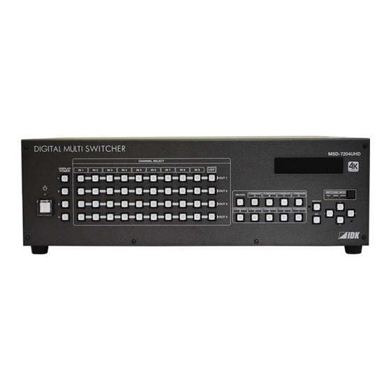
MSD-72 Series User’s Guide 2 Included items Make sure all items below are included in the package. If any items are missing or damaged, please contact IDK. One (1) main unit (Figure: MSD-7204UHD/UHDTB) One (1) power cord Two (2) rack mounting brackets (1.8 meters;... - Page 14 MSD-72 Series User’s Guide 5-pin terminal Block 3-pin terminal Block Ten (10) for MSD-7201UHDTB Two (2) for MSD-7201UHDTB Eleven (11) for MSD-7202UHDTB Two (2) for MSD-7202UHDTB Twelve (12) for MSD-7203UHDTB Two (2) for MSD-7203UHDTB Thirteen (13) for MSD-7204UHDTB Two (2) for MSD-7204UHDTB...
-
Page 15: Product Outline
MSD-72 Series User’s Guide 3 Product outline MSD-7200 series is a digital presentation switcher having a built-in scan converter. For video input, the following signal formats are supported: HDMI, DVI, composite video, S video, analog RGB, and analog YPbPr signal. Input video signal is converted to HDMI signal and output at a resolution up to 4K@60. - Page 16 MSD-72 Series User’s Guide MSD-7204UHDTB IN1 to IN3 Digital video/audio inputs Up to 98 ft. (30 m) HDMI DVI EDID emulator IN4 to IN7 Digital video/audio Video Scan Up to 98 ft. (30 m) inputs Digital video/audio Up to 98 ft. (30 m) HDMI DVI ...
-
Page 17: Features
MSD-72 Series User’s Guide 4 Features ■ Video ● Maximum resolution: 4K@60(4:4:4) ● Supports HDCP 1.4/2.2 ● Scan conversion ● Aspect ratio control ● Seamless switching ● A/D conversion output ● Anti-snow ■ Audio ● A/D, D/A conversion ● Volume adjustment ●... -
Page 18: Panels
MSD-72 Series User’s Guide 5 Panels 5.1 Front panel ⑩ ⑥ ② ③ ④ ⑤ ⑨ ① ⑪ ⑦ ⑧ [Figure 5.1] Front panel drawing (MSD-7204UHD) [Table 5.1] Front panel’s part name and description Part name Description ① Standby switch (power) Turns on/off the MSD 【See: 8.1 Power】... -
Page 19: Rear Panel
MSD-72 Series User’s Guide 5.2 Rear panel ⑤ ⑨ ⑧ ⑩ ⑪ ⑬ ⑦ ⑥ ② ① ④ ⑫ ③ [Figure 5.2] Rear panel drawing (MSD-7204UHD) ⑤ ⑨ ⑧ ⑩ ⑪ ⑬ ⑦ ⑥ ② ① ④ ⑫ ③ [Figure 5.3] Rear panel drawing (MSD-7204UHDTB) - Page 20 MSD-72 Series User’s Guide [Table 5.2] Rear panel’s part name and description Part name Description ① Main power switch Turns on/off main power of the MSD 【See: 8.1 Power】 ② HDMI input connector Input connectors for HDMI and DVI signal to connect to a source devices, such as Blu-ray players.
-
Page 21: System Configuration Example
MSD-72 Series User’s Guide 6 System Configuration Example Configuration example: source and sink devices are connected to the MSD Analog audio Power amp. SWC-2000 Speakers RS-232C Contact output Analog audio HDMI / DVI Up to 98 ft. (30 m) CD player... -
Page 22: Precautions
MSD-72 Series User’s Guide 7 Precautions Before connecting to external devices, follow the precautions below. 7.1 Installation When installing the MSD, please observe the following precautions. ● Do not place the MSD on top of another MSD. ● Do not block vent holes. Please secure the space above ambient 30 mm/1.18 inches. -
Page 23: Cabling
MSD-72 Series User’s Guide 7.2 Cabling When connecting the MSD to the external devices, please observe the following precautions. ・Read manuals of the external devices. ・ Before you connect the cable to the MSD or an external device, please remove electrification of the body by touching the metal around that is grounded. - Page 24 MSD-72 Series User’s Guide The DVI-I input connectors can be used for HDMI/DVI digital signal and other analog signal. ■ DVI signal input Use DVI-I or DVI-D cable. Signal only supports single-link. ■ HDMI signal input Use HDMI-DVI conversion cable.
- Page 25 MSD-72 Series User’s Guide TMDS Clock+ N.C. N.C. N.C. N.C. TMDS Clock- N.C. N.C. N.C. N.C. N.C. Pr / Cr N.C. N.C. N.C. Green / SOG VIDEO N.C. Blue Pb / Cb N.C. N.C. H-Sync / CS N.C. N.C. N.C.
-
Page 26: Connecting Audio Cables
Fix audio cable to the attached 5-pin terminal block, and then connecting to the MSD. The MSD supports both balanced and unbalanced signal IDK recommends using AWG 28 to AWG16 cable. The maximum peeling length is 7 mm (0.28 inch approx.) Up to 7mm (0.28 inch approx.) Up to 7mm (0.28 inch approx.) -
Page 27: Connecting Rs-232C Cable
Fix RS-232C cable to the attached3-pin terminal block, and then connect it to the MSD. IDK recommends using AWG 28 to AWG16 cable. The maximum peeling length is 7 mm (0.28 inch approx.) Up to 7 mm (0.28 inch approx.) RS-232C Tx... -
Page 28: Contact Closure
Fix a cable to the attached 6-pin terminal block, and then connecting to the MSD. IDK recommends using AWG 28 to AWG16 cable. The maximum peeling length is 7 mm (0.28 inch approx.) Up to 7 mm (0.28 inch approx.) -
Page 29: Basic Operation
MSD-72 Series User’s Guide 8 Basic operation 8.1 Power The MSD has the main power switch on the rear panel and the stanby switch on the front panel. The power status of the MSD can confirm at power LED on front panel. -
Page 30: Selecting Input Channels
MSD-72 Series User’s Guide 8.2 Selecting input channels Video and audio signal can be switched simaltanuously or independently. Press the SWITCHING MODE key to switch video and audio signal, and then use the input channel selection keys to select input channels of video and audio signal for each output channel. -
Page 31: Menu Operation
MSD-72 Series User’s Guide 8.3 Menu operation You can use the VFD screen and front panel keys to set settings. Press the “MENU/SET” key to apply the setting and to go to the next hierarchy. Press the “ESC” key to go back to the previous screen. -
Page 32: Menu Operation
MSD-72 Series User’s Guide 8.4 Menu operation You can register the control command to turn on/off the sink device. Press the key to send the control command to the sink device. 【See: 9.12.3 Command link】 DI SPLAY IN 1 IN 2 POWER [Table 8.4] Sink device power supply key... -
Page 33: Locking And Unlocking Key Lock
MSD-72 Series User’s Guide 8.6 Locking and Unlocking key lock Press and hold the “UNLOCK” key for 2 seconds or longer to set/cancel keylock for keys below. You will hear a long beep sound and then the following message is displayed for 1 second. Operation Lock can be set and done by group. -
Page 34: Initialization
MSD-72 Series User’s Guide 8.7 Initialization All settings will be reset to Factory default values by turning on the MSD while pressing the “ESC” key. Press and hold the “ESC” key until you hear a long beep sound. The following list shows the Factory default values. - Page 35 MSD-72 Series User’s Guide [Table 8.5] Factory default Menu Factory default See: OUTPUT TIMING RESOLUTION Each output channels P.52 Default AUTO MONITOR ASPECT Each output channels P.53 Default RESOLUTION INPUT ASPECT Each input channel, each input signal P,53 Default AUTO-1...
- Page 36 MSD-72 Series User’s Guide [Table 8.6] Factory default Menu Factory default See: IMAGE EFFECT INPUT SHARPNESS Each input channel, each input signal P.58 Default INPUT BRIGHTNESS Each input channel, each input signal P.58 Default 100% INPUT CONTRAST Each input channel, each input signal P.58...
- Page 37 MSD-72 Series User’s Guide [Table 8.7] Factory default Menu Factory default See: INPUT SETTING INPUT VIDEO DETECT Each input channel, digital input only P.61 Default 10000 ms HDCP INPUT ENABLE Each input channel, digital input only P.62 Default HDCP 2.2 [IN1 to IN3] HDCP 1.4 [IN4 to IN9]...
- Page 38 MSD-72 Series User’s Guide Can be set and executed only if analog RGB / analog YPbPr signal is input. [Table 8.8] Factory default Menu Factory default See: OUTPUT SETTING OUTPUT MODE Each output channels P.73 Default HDMI YCbCr 4:4:4 MODE...
- Page 39 MSD-72 Series User’s Guide [Table 8.9] Factory default Menu Factory default See: AUDIO OUTPUT LEVEL Each output channels P.81 Default 0 dB OUTPUT MUTE Each output channels P.81 Default AUDIO INPUT SELECT Each input channel, digital input only P.81 Default...
- Page 40 MSD-72 Series User’s Guide [Table 8.10] Factory default Menu Factory default See: EDID EDID DATA Each input channel, digital input only P.85 Default INTERNAL EDID PC RESOLUTION Each input channel P.86 Default IN1 to IN3 : 2160p@30 (3840x2160) IN4 to IN9 : 1080p(1920x1080)
- Page 41 MSD-72 Series User’s Guide [Table 8.11] Factory default Menu Factory default See: COM PORT PARAMETERS EACH RS-232C CHANNEL P.92 Default Baud rate : 9600 Data bit length Parity check : NONE Stop bit FUNCTION EACH RS-232C CHANNEL P.92 IP ADDRESS Default 192.168.1.199...
- Page 42 MSD-72 Series User’s Guide [Table 8.12] Factory default Menu Factory default See: PRESET COMMAND COMMAND EDIT Each control command P.98 Default [Table 9.19] Setting items of control command RECV COMMAND EDIT Each reply command P.104 Default [Table 9.24] Setting items of return command...
- Page 43 MSD-72 Series User’s Guide [Table 8.13] Factory default Menu Factory default See: BITMAP BITMAP OUTPUT Each output channels P.119 Default BACKGROUND COLOR Each output channels, each bitmap P.119 Default R : 255 G : 255 B : 255 ASPECT Each output channels, each bitmap P.119...
- Page 44 MSD-72 Series User’s Guide [Table 8.14] Factory default Menu Factory default See: OTHERS OP LOCK MODE CHANNEL P.129 CHANNEL MODE MENU PRESET LOAD COMMAND COMMAND MODE DISPLAY POW Default LOCK BUZZER P.131 Default COMMAND AUTO LOCK P.131 Default POWER SAVE P.131...
- Page 45 MSD-72 Series User’s Guide [Table 8.15] Setting condition Setting range Description Each output channels Can be set for each output channels Each input signal Can be set for each input signal Each input channel Can be set for each input channel...
-
Page 46: Web Menu Operation
MSD-72 Series User’s Guide 8.8 Web menu operation The MSD connected through a LAN can be controlled from a WEB browser, such as Microsoft Internet Explorer. JavaScript is used for the WEB browser screen. To do this, make sure to enable JavaScript of the WEB browser by referring to the HELP of each WEB browser. -
Page 47: How To Use Web Menu
MSD-72 Series User’s Guide 8.8.2 How to use WEB menu Menu Submenu IN/OUT [Fig. 8.6] WEB menu ① Select the target item from the menu. Setting items will be displayed in the sub menu. If the setting item can be set for each input or output side, the display can be changed using the pull-down menu, “IN/OUT”, placed at the right side of the submenu. -
Page 48: Menu
MSD-72 Series User’s Guide 9 Menu 9.1 Menu list Followings are menu tree of the MSD: 【See: 8.3 Menu operation (P.31) 】 ├─ Main menu │/*9.5 Input settings (P.61)*/ │ ├─Submenu ├─INPUT SETTING │ ├ │ ├─INPUT VIDEO DETECT │ ├─HDCP INPUT ENABLE │... - Page 49 MSD-72 Series User’s Guide │/*9.8 Audio settings (P.80)*/ │/*9.13 Preset memory (P.111)*/ ├─AUDIO ├─PRESET MEMORY │ ├─OUTPUT LEVEL │ ├─LOAD CROSS POINT │ ├─OUTPUT MUTE │ ├─SAVE CROSS POINT │ ├─AUDIO INPUT SELECT │ ├─EDIT CROSS POINT │ ├─INPUT OFFSET │...
-
Page 50: Input Signal Automatic Detection
MSD-72 Series User’s Guide 9.2 Input Signal Automatic Detection The MSD continuously monitors input signal. If input signal that have been input before, they are output with the same size and quality of view used previously. If input signal is not matched with any signal that have been input before, only settings of input timing is initialized and other settings are not changed. - Page 51 MSD-72 Series User’s Guide The following items are saved for each input signal. [Table 9.1] Items saved for each input signal Setting Item Aspect ratio, Aspect ratio control, Overscan, Setting position, size, and masking Display position, Display size, Masking Sharpness, Brightness, Contrast, HUE, Saturation,...
-
Page 52: Setting Position, Size, And Masking
MSD-72 Series User’s Guide 9.3 Setting position, size, and masking Position, size, and masking can be set for input side and output side. Normally, set them for input side. If edges are cut off due to enlarged display in the sink device side or if enlarging output video for all inputs at once, set them for the output side. -
Page 53: Aspect Ratio For Sink Device
MSD-72 Series User’s Guide 9.3.2 Aspect ratio for sink device Mene Top→OUTPUT TIMING→MONITOR ASPECT Setting for Each output channel Setting value ・RESOLUTION [Default] ・5:4 ・16:9 ・256:135 ・4:3 ・5:3 ・16:10 You can set the aspect ratio of the connected sink device. -
Page 54: Aspect Ratio Control
MSD-72 Series User’s Guide 9.3.4 Aspect ratio control Menu Top→OUTPUT TIMING→ASPECT PROCESS Setting for Each input channel, each input signal Setting value L-BOX/S-PANEL : letter box/side panel [Default] S-CUT/TB-CUT : Side cut/top bottom cut You can get how to restore aspect ratio. -
Page 55: Display Size
MSD-72 Series User’s Guide 9.3.7 Display size Menu Top→OUTPUT TIMING→INPUT SIZE (Input side) / OUTPUT SIZE (Output side) Setting for Input side : Each input channel, each input signal Output side : Each output channel Setting value Input side: Horizontal size (Horizontal output resolution÷4... -
Page 56: Masking
MSD-72 Series User’s Guide 9.3.8 Masking Menu Top→OUTPUT TIMING→INPUT MASKING (Input side) / OUTPUT MASKING (Output side) Setting for Input side : Each input channel, each input signal Output side : Each output channel Setting value Input side: Left side masking... -
Page 57: Background Color
MSD-72 Series User’s Guide 9.3.10 Background color Menu Top→OUTPUT TIMING→BACKGROUND COLOR Setting for Each output channel Setting value R / G / B: 0 to 255 [Default]R / G / B: 0 (black) You can set the background color of output video. -
Page 58: Quality Settings
MSD-72 Series User’s Guide 9.4 Quality settings Setting items for input channels are for correcting color bias. Image quality to be output can be set for each input side (input channels) and output side (output channels) as follows. Setting for input channels... -
Page 59: Hue
MSD-72 Series User’s Guide 9.4.4 HUE Menu Top→IMAGE EFFECT→INPUT HUE Setting for Each input channel, each input signal Setting value 0°to 359° [Default]: 0° You can set HUE of input signal. Note: This menu can be set up to 359°, but if the dot clock of input signal exceeds 170 MHz, it is treated as 0°. In this case, “*”... -
Page 60: Default Color
MSD-72 Series User’s Guide 9.4.8 Default color Menu Top→IMAGE EFFECT→IN DEFAULT COLOR (Input side) / OUT DEFAULT COLOR (Output side) Setting for Input side : Each input channel, each input signal Output side : Each output channel You can initialize settings of the following items. -
Page 61: Input Settings
MSD-72 Series User’s Guide 9.5 Input settings 9.5.1 No-signal input monitoring Menu Top→INPUT SETTING→INPUT VIDEO DETECT Setting for Each input channel (only digital input signal) Setting value OFF, 2000ms to 15000ms (100 ms steps) [Default]: 10000ms If you change the settings of EDID of the MSD or turn off/on the MSD, the source device may not output video signal. -
Page 62: Setting Hdcp Input
MSD-72 Series User’s Guide 9.5.2 Setting HDCP input Menu Top→INPUT SETTING→HDCP INPUT ENABLE Setting for Each input channel (only digital input signal) Setting value HDCP 2.2 : Supports HDCP 2.2 and HDCP 1.4 [Default]: IN1 to IN3 HDCP 1.4 : Supports HDCP 1.4 [Default]: IN4 to IN9... -
Page 63: Signal Type Of Analog Input
MSD-72 Series User’s Guide 9.5.3 Signal type of analog input Menu Top→INPUT SETTING→ANALOG INPUT TYPE Setting for Each input channel, each input signal (only analog input) Setting value ・AUTO : Automatic [Default] ・VIDEO AUTO : Video automatic ・RGB ・VIDEO : Analog RGB : Composite video ・YPbPr : Analog YPbPr... -
Page 64: Automatic Detection Of Input Video Intertuption
MSD-72 Series User’s Guide 9.5.4 Automatic detection of input video intertuption Menu Top→INPUT SETTING→INPUT OFF CHECK Setting for Each input channel Setting value ON [Default], OFF The MSD can stop outputting video immediately after input video signal is disconnected for a moment. - Page 65 MSD-72 Series User’s Guide You can select the setting saved for each signal or the current setting. “ALL FIXED”: Does not load all settings saved for each input signal but outputs the video witht the current setting. “SELECTED”: Aspect ratio, analog input signal type and audio input level can be set individually. For setting items other than settings in [Table 9.1], settings saved for each input signal are used.
-
Page 66: Setting Input Timing
MSD-72 Series User’s Guide 9.6 Setting input timing You can set input timing of analog input video if signal is input. Since the MSD loads the optimal table from the built-in tables and adjusts the input timing automatically, you do not need to set this menu. However, if signal which are not registered in the MSD tables are input or if part of the output video is cut off by using the standard table registered in the MSD, set the input timing manually. -
Page 67: Automatic Measurement
MSD-72 Series User’s Guide 9.6.1 Automatic measurement Top → INPUT TIMING → AUTO SETUP Menu Setting for Each input channel, each input signal Setting value ・NORMAL MODE [Default] ・4:3 ・5:3 ・16:10 ・NEXT ASPECT ・5:4 ・16:9 Analog RGB/analog YPbPr input video is measured to set “9.6.2 The total number of horizontal dots”, “9.6.3 Start position”, “9.6.4 Active area”, and “9.6.9 Tracking”... - Page 68 MSD-72 Series User’s Guide If automatic measurement execute only strating position changes it shows “NORMAL END”, and if the active area is changed by “NORMAL MODE” or if you set aspect ratio from “NEXT ASPECT” or directly it shows resolution which is set.
-
Page 69: The Total Number Of Horizontal Dots
MSD-72 Series User’s Guide 9.6.2 The total number of horizontal dots Top → INPUT TIMING → H TOTAL DOTS Menu Setting for Each input channel, each input signal (only analog input signal) Setting value 400DOT to 4125DOT [Default] varies depending on the input signal. -
Page 70: Active Area
MSD-72 Series User’s Guide 9.6.4 Active area Top → INPUT TIMING → H DISPLAY (Horizontal) / V DISPLAY (Vertical) Menu Setting for Each input channel, each input signal Setting value [Table 7.26] Settings of active area [Table 9.6] Settings of active area... -
Page 71: Automatic Measurement Of Start Position
MSD-72 Series User’s Guide 9.6.5 Automatic measurement of start position Top → INPUT TIMING → AUTO START POS Menu Setting for Each input channel, each input signal Setting value ALL OFF : not measuring all inputs from the input automatically... -
Page 72: Loading Device Data
MSD-72 Series User’s Guide 9.6.7 Loading device data Top → INPUT TIMING → LOAD Menu Setting for Each input channel, each input signal Device data whose input timing is registered can be loaded according to the input signal. The setting of this menu is not updated until the MENU/SET key is pressed. Make sure to press the MENU/SET key to update the setting. -
Page 73: Output Settings
MSD-72 Series User’s Guide 9.7 Output settings 9.7.1 Output mode Top → OUTPUT SETTING → OUTPUT MODE Menu Setting for Each output channel Setting value ・HDMI YCbCr 4:4:4 MODE [Default] ・HDMI RGB MODE ・HDMI YCbCr 4:2:2 MODE ・DVI MODE ・HDMI YCbCr 4:2:0 MODE You can select an output signal mode and color space of the output video. -
Page 74: Window Transaction Effect
MSD-72 Series User’s Guide 9.7.4 Window transaction effect Top → OUTPUT SETTING → VIDEO SWITCHING Menu Setting for Each output channel Setting value ・FREEZE→FADE OUT-IN [Default] ・BOTTOM→TOP WIPE ・FADE OUT-IN ・TOP→BOTTOM WIPE ・CUT ・RIGHT→LEFT WIPE ・LEFT→RIGHT WIPE You can select a window transition effect for when the video inputs is switched. -
Page 75: Hdcp
MSD-72 Series User’s Guide 9.7.7 HDCP Top → OUTPUT SETTING → HDCP OUTPUT MODE Menu Setting for Each input channel Setting value HDCP 2.2 : Encrypts HDCP via HDCP 2.2 [Default] HDCP 1.4 : Encrypts HDCP via HDCP 1.4 HDCP INPUT ONLY... -
Page 76: Deep Color
MSD-72 Series User’s Guide 9.7.9 Deep Color Top → OUTPUT SETTING → DEEP COLOR OUTPUT Menu Setting for Each output channel Setting value 24-BIT COLOR [Default], 30-BIT COLOR You can select the color depth of HDMI signal. “30-BIT COLOR”: signal is output with “30-BIT COLOR” only if a sink device supporting Deep Color is connected. -
Page 77: Hdcp Re-Authentication
MSD-72 Series User’s Guide 9.7.11 HDCP re-authentication Top → OUTPUT SETTING → HDCP AUTHENTICATION Menu Setting for Each output channel If a sink device supporting HDCP is connected, HDCP is authorized automatically. You can re-authorize HDCP manually using this menu (connection Reset is performed automatically, but it can be performed manually using this menu). - Page 78 MSD-72 Series User’s Guide ■ AUTO SWITCHING OFF AUTO SWITCHING OFF menu switches input signal when the input signal changes from “ON” to “OFF”. The MSD switches input signal automatically based on following conditions; ・Switches to the input channel having input signal and highest priority.
-
Page 79: Masking Time After Automatic Switching Of Input Channel
MSD-72 Series User’s Guide 9.7.13 Masking time after automatic switching of input channel Top → OUTPUT SETTING → AUTO SWITCHING MASK Menu Setting for Each output channel Setting value 0s000ms to 999s999ms [Default: 0s000 ms] You can set the time from when input channel is switched automatically until when the next automatic switching is performed. -
Page 80: Audio Settings
MSD-72 Series User’s Guide Audio settings HDMI digital audio supports the following formats. Set audio depending on device connected to the HDMI output connector. Only “2 channel linear PCM” can be input by Factory default. If you want to use “Multi channel linear PCM” or bit stream signal (compressed audio), set “Audio format”... -
Page 81: Output Level
MSD-72 Series User’s Guide 9.8.1 Output level Top → AUDIO → OUTPUT LEVEL Menu Setting for Each output channel Setting value -60dB to +10dB [Default] ±0dB You can set the audio output level. If you change the output level while audio output mute is set to ”ON”, mute is canceled. -
Page 82: Lip Sync
MSD-72 Series User’s Guide 9.8.5 Lip sync Top → AUDIO → OUTPUT LIP SYNC (Output side) / INPUT LIP SYNC (Input side) Menu Setting for Output side : Each output channel Input side : Each input channel, each input signal Setting value 0FRAME to 8FRAME [Default]: 0FRAME You can adjust the gap between video (motion) and audio (sound). -
Page 83: Audio Output Connector
MSD-72 Series User’s Guide 9.8.7 Audio output connector Top → AUDIO → OUTPUT CONNECTOR Menu Setting for Each output channel Setting value [Table 9.11] Settings of audio output control [Table 9.11] Settings of audio output control Analog audio HDMI Setting value... -
Page 84: Test Tone
MSD-72 Series User’s Guide 9.8.9 Test tone Top → AUDIO → TEST TONE Menu Setting for Each output channel Setting value Test tone: OFF [Default],1kHz ,400Hz Speaker: ・ALL [Default] ・LOW FREQUENCY EFFECT ・FRONT L/R ・FRONT CENTER ・REAR L/R ・REAR LEFT ・REAR L/R CENTER... -
Page 85: Edid (Extended Display Identification Data)
MSD-72 Series User’s Guide EDID (Extended Display Identification Data) You can set or customize EDID to be sent to the source device. Change the setting as needed. ■ Setting EDID (1) If you use copied EDID, copy the target EDID from the sink device. -
Page 86: Resolution For Pcs
MSD-72 Series User’s Guide 9.9.2 Resolution for PCs Top → EDID → PC RESOLUTION Menu Setting for Each input channel Setting value ・SVGA (800x600) ・WXGA (1366x768) ・WUXGA(1920x1200) ・XGA (1024x768) ・SXGA+ (1400x1050) ・QWXGA(2048x1152) ・720p (1280x720) ・WXGA+ (1440x900) ・WQHD(2560x1440) ・WXGA (1280x768) ・WXGA++ (1600x900) ・WQXGA(2560x1600) - Page 87 MSD-72 Series User’s Guide [Table 9.12] Supported resolution Supported resolution Input resolution settings 800x600 1024x768 1280x720[D4] 1280x768 1280x800 1280x960 1280x1024 1360x768 1366x768 1400x1050 1440x900 1600x900 1600x1200 1680x1050 1920x1080i[D3] 1920x1080p[D5] 1920x1200 2048x1152 2560x1440 2560x1600 2160p (30p) 2160p (60p) Y: Supported N: Not supported...
-
Page 88: Input Resolution For Av Devices
MSD-72 Series User’s Guide 9.9.3 Input resolution for AV devices Top → EDID → AV RESOLUTION Menu Setting for Each input channel (only digital input signal) Setting value ・AUTO [Default] ・1080i ・2160p@60 4:4:4 ・UNUSED ・1080p ・4096x2160@30 ・480p ・2160p@30 ・4096x2160@60 4:2:0 ・720p... -
Page 89: Deep Color
MSD-72 Series User’s Guide 9.9.4 Deep Color Top → EDID → DEEP COLOR INPUT Menu Setting for Each input channel (Digital input only) Setting value 24-BIT COLOR [Default], 30-BIT COLOR You can set the color depth to be output from the source device. -
Page 90: Speaker Configuration
MSD-72 Series User’s Guide 9.9.6 Speaker configuration Top → EDID → SPEAKER Menu Setting for Each input channel (only digital input signal) Setting value Setting mode : AUTO [Default], MANUAL Each speaker : ON, OFF The number of speakers: 1 to 8 [Table 9.15] Default speaker configuration... -
Page 91: Copying Edid
MSD-72 Series User’s Guide You can set the speaker configuration of multi channel audio. This menu is valid only if you select “INTERNAL EDID” for “9.9.1 EDID”, you select a resolution other than “UNUSED” for “9.9.3 Input resolution for AV devices”. -
Page 92: Rs-232C
MSD-72 Series User’s Guide 9.10 RS-232C The RS-232C port of the MSD can output communication command control from PCs and can output control command to external devices from the MSD. The operation mode will be switched according to “9.10.2 RS-232C operation mode”. -
Page 93: Lan
MSD-72 Series User’s Guide 9.11 LAN The LAN connector of the MSD can be used for outputting communication command control from PCs and for outputting control command to external devices from the MSD. Operation mode will be switched according to the setting of “9.11.2 LAN operation mode”. The MSD has eight connections that can be set individually. -
Page 94: Lan Operation Mode
MSD-72 Series User’s Guide 9.11.2 LAN operation mode Top → LAN → FUNCTION Menu Setting for Each connection Setting value [Table 9.17] Setting items of LAN operation mode [Table 9.17] Setting items of LAN operation mode Operation mode Setting Receiver mode... -
Page 95: Tcp Port Number
MSD-72 Series User’s Guide 9.11.3 TCP port number Top → LAN → PORT NUMBER Menu Setting for Each connection Setting value [Table 9.18] Settings of TCP port number [Table 9.18] Settings of TCP port number Setting value Communication command control... -
Page 96: Setting Control Command
MSD-72 Series User’s Guide 9.12 Setting control command You can control external devices (for example, turning ON/OFF projectors) via RS-232C, LAN, contact closure, or CEC. You can register up to 32 commands in the MSD. Registered control commands will be associated with control command execution keys (COMMAND A to COMMAND I) or execution conditions such as switching video or audio. - Page 97 MSD-72 Series User’s Guide ■ Control command via RS-232C / LAN communication Control commands can be sent from RS-232C port/LAN connector of the MSD. Before executing control command, set the operation mode of the connector to “TRANSMITTER”. 【See: 9.10.2 RS-232C operation mode】...
-
Page 98: Registering/Editing Control Command
MSD-72 Series User’s Guide 9.12.1 Registering/editing control command Top → PRESET COMMAND → COMMAND EDIT Menu Setting for Each command Setting value [Table 9.19] Setting items of control command You can create and edit up to 32 control commands. The setting of this menu is not updated until the MENU/SET key is pressed. Make sure to press the MENU/SET key to update the setting. - Page 99 MSD-72 Series User’s Guide [Table 9.20] Setting items of control command Setting Item Description Range RECV DISPLAY Set whether received data is displayed OFF [Default] or not. ASCII DELIMITER Set the delimiter to be sent at the end of NONE [Default] the received data.
- Page 100 MSD-72 Series User’s Guide If you set “RECV DISPLAY” to “OFF”, you cannot set this item. If you set “RECV DISPLAY” to “ASCII” or “HEX”, you cannot set this item. If you set only “LOOP BACK” of communication ports to “ON”, you do not need to set this item.
- Page 101 MSD-72 Series User’s Guide [Table 9.21] PJLink command (class1) list Command Description R (SP) 0 Power off (Standby) R (SP) 1 Power on (Lamp on) R (SP) ? Get power status T (SP) 1 CR Switch input to RGB CR Switch input to VIDEO...
- Page 102 MSD-72 Series User’s Guide [Tabel 9.23] Individual reply command of status acquisition commands Command Description Reply command to power status commands (CR) Stand by (CR) Power ON (CR) Cooling (CR) Warming up Reply command to input status commands (CR) RGB selected...
- Page 103 MSD-72 Series User’s Guide *11 20 to FF in hex: up to 64 characters. *12 20 to 7F in hex: up to 32 characters.
-
Page 104: Registering/Editing Reply Command
MSD-72 Series User’s Guide 9.12.2 Registering/editing reply command Top → PRESET COMMAND → RECV COMMAND EDIT Menu Setting for Each command Setting value [Table 9.24] Setting items of return command You can create and edit up to 32 reply commands. - Page 105 MSD-72 Series User’s Guide ■ Setting loop back function If the MSD sends a communication command back to the MSD itself using the loop back function, the MSD replies “OK” if processed normally while it replies “NG” if parameter or command is incorrect. (This differs from reply commands to communication commands received externally;...
- Page 106 MSD-72 Series User’s Guide ■ Mask data The received data without mask data and “AND” of each bit is compared with the reply command data. Set “MASK” to “FF”. Since “FF” is set by Factory default, you do not need to change the mask data normally.
-
Page 107: Command Link
MSD-72 Series User’s Guide 9.12.3 Command link Top → PRESET COMMAND → COMMAND LINK Menu Setting for [Table 9.26] Control command execution condition Setting value OFF [Default], COMMAND 1 to COMMAND 32 The MSD has 108 command execution conditions as shown below. If these execution conditions are met, control commands which are associated beforehand will be executed. -
Page 108: Command Execution
MSD-72 Series User’s Guide VIDEO:OUT2-IN9, channel of OUT2 VIDEO:OUT4-IN9, channel of OUT4 VIDEO:OUT2-OFF VIDEO:OUT4-OFF AUDIO:OUT2-IN1 to Selecting audio input AUDIO:OUT4-IN1 to Selecting audio input AUDIO:OUT2-IN9, channel of OUT2 AUDIO:OUT4-IN9, channel of OUT4 AUDIO:OUT2-OFF AUDIO:OUT4-OFF 9.12.4 Command execution Top → PRESET COMMAND → COMMAND EXECUTION... - Page 109 MSD-72 Series User’s Guide ▪ Reply commands registered in “9.12.2 Registering/editing reply command” ▪ Associations of control commands registered in “9.12.3 Command link” Use this menu to delete or set them from the first step again. A long buzzer will sound when the initialization is completed by pressing the MENU/SET key.
-
Page 110: Command Execution Key: Lighting Condition
MSD-72 Series User’s Guide 9.12.7 Command execution key: Lighting condition Top → PRESET COMMAND → COMMAND TALLY Menu Setting for Each control command execution key Setting value REGISTERED [Default] : Lights if a control command is registered *1 *2 EXECUTION: Lights while a control command is executed If you set “LINK”... -
Page 111: Preset Memory
MSD-72 Series User’s Guide 9.13 Preset memory 9.13.1 Loading cross pooint Top → PRESET MEMORY → LOAD CROSS POINT Menu Setting value No.1 to No.9 You can load the I/O channel settings of video and audio saved in the cross point memory. -
Page 112: Editing Cross Point
MSD-72 Series User’s Guide 9.13.3 Editing cross point Menu Top→PRESET MEMORY→EDIT CROSS POINT Setting for Each cross point memory Setting value [Table 9.28] Editing items of cross point [Table 9.28] Editing items of cross point Setting item Setting value Default... -
Page 113: Loading All Settings
MSD-72 Series User’s Guide 9.13.4 Loading all settings Top → PRESET MEMORY → LOAD ALL SETTING Menu Setting value No.1 to No.8 You can load all settings saved in the preset memory. Once you perform this operation, all settings related to video and audio I/O except for some environmental settings will be updated. -
Page 114: Saving All Settings
MSD-72 Series User’s Guide 9.13.5 Saving all settings Top → PRESET MEMORY → SAVE ALL SETTING Menu Setting value No.1 to No.8 You can save up to eight preset memories (up to 10 characters) of the following settings: The setting of this menu is not updated until the MENU/SET key is pressed. Make sure to press the MENU/SET key to update the setting. -
Page 115: Copying Output Setting
MSD-72 Series User’s Guide 9.13.6 Copying output setting Menu Top→PRESET MEMORY→COPY OUTPUT MEMORY Setting value OUT1 to OUT4 → OUT1 to OUT4 You can copy the setting data of the selected output channel to other output channels using “MENU/SET” key. -
Page 116: Startup Setting
MSD-72 Series User’s Guide 9.13.7 Startup setting Top → PRESET MEMORY → START UP Menu Setting value [Table 9.31] Startup settings [Table 9.31] Startup settings Item Setting value Operation at startup Last channel LAST CHANNEL [Default] Starts with the setting last time the MSD powered off. -
Page 117: Setting Bitmap
9.14 Setting bitmap 9.14.1 Sending bitmap file You can set the bitmap image to be displayed on the sink device. Up to four bitmaps can be registered. IDK’s logo is displayed by Factory default. Bitmaps can be enlarged but cannot be reduced. The larger the resolution is, the longer the output time will be, and it may take a maximum of approximately six seconds to output a bitmap. - Page 118 MSD-72 Series User’s Guide Web menu operation】 [Fig. 9.28] Transferring bitmap Once bitmap file is transferred correctly, the message is displayed. Click the “OK” button of the dialog box to register bitmap file. Do not operate the WEB menu or turn off the MSD until the registration completes.
-
Page 119: Outputing Bitmap Image
MSD-72 Series User’s Guide 9.14.2 Outputing bitmap image Top → BITMAP → BITMAP OUTPUT Menu Setting for Each output channel Setting value OFF [Default], ON (BITMAP1 ON to BITMAP4 ON) You can enable/disable the bitmap image output. If several bitmaps are registered, select the bitmap number you want to output. -
Page 120: Display Position
MSD-72 Series User’s Guide 9.14.5 Display position Top → BITMAP → POSITION Menu Setting for Each output channel, each bitmap Setting value [Figure 9.30] Display position ● TOP-LEFT ● TOP-RIGHT ● CENTER [Default] ● ● BOTTOM-RIGHT BOTTOM-LEFT [Figure 9.30] Display position You can set the display position of the bitmap. -
Page 121: Dividing Memory Area
MSD-72 Series User’s Guide 9.14.8 Dividing memory area Menu Top→BITMAP→DIVIDE MEMORY Setting value [Table 9.34] Dividing memory area You can register up to four bitmaps within the available memory area by dividing the memory. You can select one of three dividing modes or specify the size you want to divide manually. - Page 122 MSD-72 Series User’s Guide ■ Displaying method “BLOCK” If you select “BLOCK” for “DISPLAY”, the current start and end block positions are displayed on the left of the VFD screen. If a bitmap is registered, the final block position is displayed in parentheses. The start and end block positions after divide are displayed on the right.
-
Page 123: Input Image Capture
MSD-72 Series User’s Guide 9.14.9 Input image capture Top → BITMAP → VIDEO CAPTURE Menu Setting value [Table 9.35] Setting items for input video capture [Table 9.35] Setting items for input video capture Setting item Setting value Default Output channel... - Page 124 MSD-72 Series User’s Guide From browser You can capture and save an input video through a WEB browser as well. Step1) If the memory area is divided, select the registered area of the captured image. Step2) Set “FREEZE” to “ON”. You can skip this step. This freeze is only temporary. If input channel is switched or input signal changes, the freeze is released and the input video will be output.
-
Page 125: Startup Settings
MSD-72 Series User’s Guide 9.15 Startup settings 9.15.1 Power switch Top → POWER ON SETTING → POWER SWITCH Menu Setting value AUTO [Default], OFF, ON You can set the MSD’s power-on state. “AUTO” : The same state as the MSD was before turning off the main power switch. -
Page 126: Display Power Keys
MSD-72 Series User’s Guide 9.15.2 DISPLAY POWER keys Top → POWER ON SETTING → DISPLAY POWER Menu Setting for Each output channel Setting value AUTO [Default], OFF, ON You can set the DISPLAY POWER key state for when the MSD is powered on. -
Page 127: Unlock Keys
MSD-72 Series User’s Guide 9.15.3 UNLOCK keys Top → POWER ON SETTING → COMMAND UNLOCK Menu Setting value AUTO [Default], COMMAND, PRESET LOAD, LOCK You can set the UNLOCK key state for when the MSD is powered on. “AUTO” : The same state as it was before turning off the MSD or standby “COMMAND”... -
Page 128: Operation Lock
MSD-72 Series User’s Guide 9.15.4 Operation lock Top → POWER ON SETTING → OPERATION LOCK Menu Setting value AUTO [Default], UNLOCK, LOCK You can set the operation lock state for when the MSD is powered on. “AUTO” : The same state as it was before turning off the MSD or standby. -
Page 129: Other Settings
MSD-72 Series User’s Guide 9.16 Other settings 9.16.1 Operation lock mode Top → OTHERS → OP LOCK MODE Menu Setting for CHANNEL, CHANNEL MODE, MENU, PRESET LOAD, COMMAND, COMMAND MODE, DISPLAY POW Setting value LOCK [Default], UNLOCK You can set the operation lock mode for each key group on the front panel. - Page 130 MSD-72 Series User’s Guide SWITCHING UNLOCK key MODE key Input channel selection keys MENU/SET key DISPLAY POWER keys Control command Press and hold more than execution key 5 sec to lock and release [Figure 9.34] Keys for operation lock (MSD-7204UHD)
-
Page 131: Buzzer
MSD-72 Series User’s Guide 9.16.2 Buzzer Top → OTHERS → BUZZER Menu Setting value ON [Default], OFF You can turn ON/OFF the buzzer function (sounding every time you press a front panel key). 9.16.3 Automatic lock for control command execution keys Top →... -
Page 132: Input Channel Automatic Linking
MSD-72 Series User’s Guide 9.16.6 Input channel automatic linking Top → OTHERS → INPUT CHANNEL LINK Menu Setting value VIDEO: OFF [Default], OUT1, OUT2, OUT3, OUT4 AUDIO: OFF [Default], OUT1, OUT2, OUT3, OUT4 Menus to be adjusted for each channel can be adjusted after the input number is selected. With this menu, you can select input to be adjusted automatically by switching input in “8.2 Selecting input channels”. -
Page 133: Top Vfd Screen
MSD-72 Series User’s Guide 9.16.7 Top VFD screen Top → OTHERS → TOP DISPLAY Menu Setting value [Figure 9.36] Top screen Default AUDIO VOLUME MSD-7204UHD [OUT1 AUDIO] MUTE You can enable/disable mute function everytime pressing the “ESC” key. MONITOR STATUS... -
Page 134: Input Signal Status
MSD-72 Series User’s Guide 9.16.8 Input signal status Top → OTHERS → INPUT STATUS Menu Setting value [Table 9.44] Input signal status You can display the input signal status that is input from HDMI and DVI input connectors. [Table 9.44] Input signal status... - Page 135 MSD-72 Series User’s Guide ▪ Format of video input signal [Table 9.46] Format of video input signal Signal type Items to be displayed Example Format type, vertical synchronous 1080p 59.94Hz SDTV / HDTV signal frequency Horizontal / Vertical resolution, vertical 800 x 600 60.00Hz...
-
Page 136: Sink Device Status
MSD-72 Series User’s Guide 9.16.9 Sink device status Top → OTHERS → MONITOR STATUS Menu Setting value [Table 9.48] Sink device status You can display the status of sink device connected to video output connectors. [Table 9.48] Sink device status... - Page 137 MSD-72 Series User’s Guide ▪ Error code From the left, statuses of video output, digital audio output, and analog audio output are displayed. (Example: AAA) [Table 9.50] Error code Code Video output Audio output If any number or character is not displayed, video or audio is output correctly.
-
Page 138: Displaying Edid Of Sink Device
MSD-72 Series User’s Guide 9.16.10 Displaying EDID of sink device Top → OTHERS → EDID STATUS Menu Setting value [Table 9.51] EDID information of sink device You can display EDID information of the sink device that is connected to the video output connector. -
Page 139: Displaying Version
MSD-72 Series User’s Guide 9.16.11 Displaying version Top → OTHERS → VERSION Menu Show contents Product name, firmware version You can display the product name and firmware version. -
Page 140: Product Specification
MSD-72 Series User’s Guide 10 Product specification Specifications and appearance are subject to change without notice. Item Description 3 inputs HDMI Deep Color (*1) / DVI 1.0 TMDS single link, HDCP 1.4 / 2.2 TMDS clock: 25 MHz to 300 MHz, TMDS data rate: 0.75 Gbps to 18 Gbps... - Page 141 ・1080p@60: when IDK’s AWG 24 cable was used and signals of 1080p@60 24 bit / pixel (8 bit / component) was input or output. ・4K@60: when IDK’s 18 Gbps supported cable was used and signals of 4K@60 24 bit / pixel (8 bit / component) was input or output.
-
Page 142: Trouble Shooting
MSD-72 Series User’s Guide 11 Trouble shooting This chapter recommends what to do if you have problems operating the MSD. In case the MSD does not work correctly, please check the following items first. ・Are the MSD and all devices plugged in and powered on normally? ・Are cables connected correctly? - Page 143 MSD-72 Series User’s Guide Analog input video is [3] Change the input signal type. not output. - Video is not output [4] If the source device has multiple output connectors, check the video output settings of the source device. -...
- Page 144 MSD-72 Series User’s Guide analog composite video or analog S-Video is input. The left, right, top If the problem occurs only when “CROSS HATCH” (a test pattern) and bottom sides are is output, the sink device enlarges and displays the video. Adjust cut off.
- Page 145 MSD-72 Series User’s Guide horizontally. device. Check the set aspect ratio of the input signal. - Check the monitor setting of the source device (such as 4:3, 16:9, letter box and the like). For analog input, signal that cannot be recognized by the MSD and wrong aspect ratio may be applied.
- Page 146 MSD-72 Series User’s Guide ●Audio input Audio is not output. If audio is not output, first check the error code in “9.16.9 Sink device status (P.136)”. (The MSD has multiple output connectors. Find the error code of the output connector that does not output audio.)
- Page 147 MSD-72 Series User’s Guide [14] Is video being output correctly? If not, check [1], [2], [5] and [6]. - Audio is not output from digital input. [15] Is DVI signal output from the source device? You can check the input signal type in “9.16.8 Input signal status (P.134)”.
- Page 148 MSD-72 Series User’s Guide control commands in order to enable these keys. When a control command is executed using a front panel key, all keys are disabled until the command is executed or “INVALID TIME” passes. Check the set time of “POWER SWITCH ON” that prevent accidental operation.
- Page 149 MSD-72 Series User’s Guide ●Others Input signal When the CEC connection changes, EDID may change. In this temporarily case, input signal is interrupted. Check the CEC connection disappear when input settings. channel is switched. Devices cannot be Are HDMI cables supporting CEC being used?
- Page 150 MSD-72 Series User’s Guide User’s Guide of MSD-72 Series Ver.1.4.0 Issued on: 5 September 2018 Headquarters IDK Corporation 7-9-1 Chuo, Yamato-shi, Kanagawa-pref. 242-0021 JAPAN TEL: +81-46-200-0764 FAX: +81-46-200-0765 Email: idk_eng@idk.co.jp URL: http: //www.idkav.com IDK America Inc. 72 Grays Bridge Road Suite 1-C, Brookfield, CT 06804 TEL: +1-203-204-2445 Email: sales@idkav.com URL: http: //www.idkav.com...
Need help?
Do you have a question about the MSD-72 Series and is the answer not in the manual?
Questions and answers