Table of Contents
Advertisement
Quick Links
Download this manual
See also:
User Manual
Advertisement
Table of Contents

Related Manuals for IDK MSD-402


Summary of Contents for IDK MSD-402
- Page 1 Presentation Switcher MSD-402 <User’s Guide> Ver.1.0.0 ● Thank you for choosing our Digital Multi Switcher. ● To ensure the best performance of this product, please read this User’s Guide fully and carefully before using it and keep this manual beside the product.
- Page 2 MSD-402 User’s Guide Trademarks ● Blu-ray Disc and Blu-ray are trademarks of Blu-ray Disc Association. ● The terms HDMI and HDMI High-Definition Multimedia Interface, and the HDMI Logo are trademarks or registered trademarks of HDMI Licensing, LLC in the United States and other countries.
- Page 3 ● Some of the contents in this user’s guide such as appearance diagrams, menu operations, communication commands, and so on may differ from the MSD depending on the version. ● This Users guide is subject to change without notice. You can download the latest version from IDK’s website at: http://www.idk.co.jp/en/index.html...
-
Page 4: Safety Instructions
MSD-402 User’s Guide Safety instructions Read and understand all safety and operating instructions before using this product. Follow all instructions and cautions as detailed in this document. Enforcement Symbol Description Indicates the presence of a hazard that may result in death or serious... - Page 5 The product is intended to be installed by skilled technicians. For installation, please contact a system integrator or IDK. Otherwise, it may cause fire, electric shock, injury, or property damage. Set the power plug in a convenient place to unplug easily.
- Page 6 MSD-402 User’s Guide Caution Do not place the product in any place where it will be subjected to high temperatures. If the product is subjected to direct sunlight or high temperatures, it may cause fire. Do not place the product in humid, oil smoke, or dusty place.
- Page 7 MSD-402 User’s Guide Altitude: Do not place the product at elevations of 2,000 meters (6562 feet) or higher above sea level. Failure to do so may shorten the life of the internal parts and result in malfunctions. Instruction...
-
Page 8: Table Of Contents
MSD-402 User’s Guide Table of Contents Included items .............................11 Product outline ............................12 Features ..............................13 Panels ..............................14 Front panel .............................14 Rear panel............................15 Example connection ..........................16 Precautions ............................17 Installing rubber feet ........................17 Installation ............................17 Cabling ............................18 6.3.1 Cables ............................18 6.3.2 Twisted pair cable ........................19 6.3.3... - Page 9 MSD-402 User’s Guide Quality settings (WEB menu) ......................47 8.5.1 Sharpness ..........................49 8.5.2 Brightness ..........................49 8.5.3 Contrast ..........................49 8.5.4 HUE ............................49 8.5.5 Saturation ..........................50 8.5.6 Black level ..........................50 8.5.7 Gamma ...........................50 8.5.8 Default color ..........................50 Input settings (WEB menu) ......................51 8.6.1 No-signal input monitoring .......................52...
- Page 10 MSD-402 User’s Guide 8.11.2 IP address/subnet mask/gate way address ................80 8.11.3 TCP port number........................81 8.11.4 MAC address ..........................81 8.12 Preset memory (WEB menu) ......................82 8.12.1 Loading cross point .........................83 8.12.2 Saving cross point ........................83 8.12.3 Editing cross point ........................84 8.12.4 Loading all settings .........................84 8.12.5 Saving all settings ........................85...
-
Page 11: Included Items
MSD-402 User’s Guide 1 Included items Make sure all items below are included in the package. If any items are missing or damaged, please contact IDK. One (1) MSD-402 (main unit) One (1) lockalable DIN plug AC adapter Three (3) cord clamps... -
Page 12: Product Outline
MSD-402 User’s Guide 2 Product outline MSD-402 (hereafter referred to as “the MSD”) Presentation Switcher provides 4 inputs and 2 outputs and has a built-in scan converter. For video input, 2 HDBaseT and 2 HDMI/DVI are included. Input video signals are converted to HDMI/DVI signals or HDBaseT signals output at resolutions at up to QWXGA or 1080p. -
Page 13: Features
MSD-402 User’s Guide 3 Features ■ Video ・ Up to QWXGA (RB) or 1080p ・ HDMI input cable EQ INPUT: up to 33 ft. to 99 ft. approx. / 10 m to 30 m ・ Up to 328.08 ft. approx. / 100 m extension over a Cat6 cable ・... -
Page 14: Panels
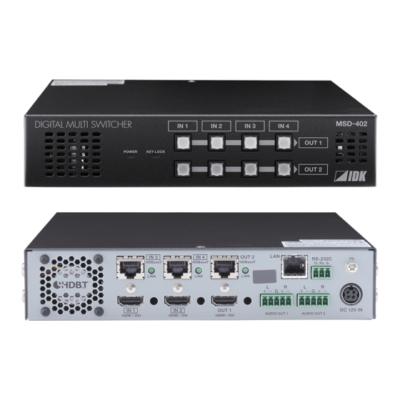
MSD-402 User’s Guide 4 Panels 4.1 Front panel ① ② ③ [Figure 4.1] Front panel drawing [Table 4.1] Front panel’s part name and description Part name Description ① POWER LED Shows power status of the MSD ON: Power is supplied to the MSD OFF: Power is not supplied to the MSD ②... -
Page 15: Rear Panel
③ HDBaseT input Digital (video/audio) signal can be extended up to 100 m/328.08 ft. using connector an IDK’s HDC transmitter together. 【See: 6.3.2 Twisted pair cable (P.19) 】 ④ HDMI output connector Output connector for HDMI and DVI signal to connect to sink devices such as LC monitors and projectors ⑤... -
Page 16: Example Connection
MSD-402 User’s Guide 5 Example connection HDMI / DVI HDMI / DVI HDBaseT Cat6 Tx for HDMI Cat6 Rx for HDMI HDC-RH100-C HDC-TH100-C Up to 6.56 ft. / 2 m Up to 6.56 ft. / 2 m Up to 330 ft. / 100 m... -
Page 17: Precautions
MSD-402 User’s Guide 6 Precautions Before connecting to external devices, follow the precautions below. 6.1 Installing rubber feet Please clean up the MSD main unit, and then install rubber feet to the four corners of the MSD. 6.2 Installation When installing the MSD, please observe the following precautions. -
Page 18: Cabling
[Figure 6.1] Attaching a cable clamp 6.3.1 Cables IDK Corporation provides various digital cables such as HDMI, DVI, and twisted pair cables. Please choose appropriate cables for your system configuration. For analog audio and RS-232C, please use on processing the cable to fit the connectors. -
Page 19: Twisted Pair Cable
50 m/164.04 ft. Cat6 * CAT.5E HDC cable developed by IDK Corporation is double shielded twisted pair cable for high quality video transmission. It protects video signals from external noise or other interferences by having double shielded structure. Its transmission characteristic meets 500 MHz up to 100 m/328.08 ft., and it is certified and recommended by HDBaseT alliance. -
Page 20: Connecting Audio Cables
Please fix audio cable to the attached terminal block (5-pin), and then connecting to the MSD. The MSD supports both balanced and unbalanced signals IDK recommends using AWG 28 to AWG16 cable. The maximum peeling length is 7 mm (0.28 inch approx.) Up to 7mm (0.28 inch approx.) -
Page 21: Din Plug Ac Adapter
MSD-402 User’s Guide 6.3.5 DIN plug AC adapter ■ Attaching/removing AC plug The AC plug for DIN plug AC adapter is different by each country. Please use appropriate AC plug. Removing: Removes AC plug by sliding AC plug from AC adapter main unit whole holding down the partial knob. - Page 22 MSD-402 User’s Guide ■ Connecting DC plug Please connect DC plug to the MSD until you can hear small sound of fixing. When you disconnect DC plug from the MSD, please hold the part which is specified in following figure.
-
Page 23: Basic Operation
MSD-402 User’s Guide 7 Basic operation 7.1 Required time The MSD turns on when AC adapter is connected and power is supplied. All LEDs except POWER LED turn on until the MSD is ready. After the MSD is turned on, it takes few seconds to take next operation. -
Page 24: Setting And Canceling Key Lock
MSD-402 User’s Guide 7.3 Setting and canceling key lock Key lock operation is assigned to “IN 1” key at OUT 1. You can lock/ cancel keys by pressing “IN 1” key at OUT 1 two or longer seconds. If the MSD’s keys are locked, KEY LOCK LED is ON. If key lock is canceled, KEY LOCK LED is OFF. -
Page 25: Initialization
MSD-402 User’s Guide 7.4 Initialization Initialization operation is assigned to “IN 1” key at OUT 1. You can initialize the MSD by turing on while pressing “IN 1” key at OUT 1. Please keep pressing “IN 1” key at OUT 1 until LEDs except POWER LED start blinking. - Page 26 MSD-402 User’s Guide [Table 7.3] Factory default settings (2/3) Function Factory default setting Page Setting position, size, and masking Sharpness Input Brightness 100% Input Contrast R / G / B: 100% 0° Saturation 100% ±0.0% Black level Output Brightness 100%...
- Page 27 MSD-402 User’s Guide Test tone [Table 7.4] Factory default settings (3/3) Function Factory default setting Page EDID EDID INTERNAL EDID Resolution for PCs 1080p (1920x1080) Input resolution for AV devices AUTO Deep Color 24-BIT COLOR Audio format Linear PCM 48kHz...
-
Page 28: Pinp (Picuture In Picuture)
JavaScript is used for the MSD WEB browser. When you set the MSD from WEB browser menu, please enable JavaScript before setting up. Please confirm each browser’s help menu if you do no know how to enable JavaScript. 【FYI】 IDK confirms and tests following environment Windows 7 Professional WEB browser... -
Page 29: Web Menu
MSD-402 User’s Guide 7.6.2 WEB menu ② ① ③ [Figure 7.5] WEB menu ① Selected [MENU] page is displayed to right side ② There are menu that can switch channels for setting You can edit channel name which is displayed into tab. -
Page 30: Menu
MSD-402 User’s Guide 8 Menu 8.1 WEB menu list 【See: 7.6 WEB menu operation (P.28) 】 8.6 Input settings (WEB menu) (P.51) 8.3 Crosspoint operation (WEB menu) (P.34) [MENU] [CROSS POINT] [MENU] [INPUT SETTING] CROSS POINT CROSS POINT CROSS POINT... - Page 31 MSD-402 User’s Guide 8.9 Audio settings (WEB menu) (P.64) 8.13 Setting bitmap (WEB menu) (P.88) [MENU] [AUDIO] [MENU] [BITMAP] CROSS POINT OUTPUT AUDIO LEVEL CROSS POINT SEND BITMAP OUTPUT TIMING BITMAP OUTPUT OUTPUT TIMING OUTPUT MUTE IMAGE EFFECT OUTPUT CONNECTER...
-
Page 32: Input Signal Automatic Detection
MSD-402 User’s Guide ■ Setting/default values Some menus can be set for each input or output, and each setting range is mentioned in the each menu description. [Table 8.1] Setting range Setting range Description Each output channel Can be set for each output channel. - Page 33 MSD-402 User’s Guide The MSD saves data of 50 input devices for each channel, and the data is used to check whether the input signal have been input before or not. To save the data of the 51st device, the oldest data that have not been input recently will be deleted, instead.
-
Page 34: Crosspoint Operation (Web Menu)
MSD-402 User’s Guide 8.3 Crosspoint operation (WEB menu) You can set input/ouput related settings from this page. You can also set PinP output ON / OFF setting and key lock. ② ① ③ ④ [Figure 8.5] Crosspoint page ① 8.3.1 Selecting input channel (WEB menu) (P.35) ②... -
Page 35: Selecting Input Channel (Web Menu)
MSD-402 User’s Guide 8.3.1 Selecting input channel (WEB menu) CROSS POINT → CROSS POINT Menu Setting for Each output channel, each PinP output Setting values :IN1, IN2, IN3, IN4, OFF [Default] OUT1 :IN1, IN2, IN3, IN4, OFF [Default] OUT2 :IN1, IN2, IN3, IN4, OFF [Default] PinP1 :IN1, IN2, IN3, IN4, OFF [Default]... -
Page 36: Editing Channel Name
MSD-402 User’s Guide 8.3.3 Editing channel name CROSS POINT → CROSS POINT Menu Setting for Input: each input channel Output: each output channel PinP: each PinP output Setting values [Table 8.3] Editing channel name By pressing “NAME EDIT” button, following page is displayed and you can set and edit input and output channel name. -
Page 37: Setting And Canceling Key Lock (Web Menu)
MSD-402 User’s Guide 8.3.4 Setting and canceling key lock (WEB menu) CROSS POINT → CROSS POINT Menu Setting values OFF [Default], ON By pressing “KEY LOCK” button, you can lock the MSD’s front panel keys. “KEY LOCK” button is “ON” when front panel keys are locked. -
Page 38: Output Timing (Web Menu)
MSD-402 User’s Guide 8.4 Output timing (WEB menu) You can set output timing from this page and select channel which you want to set from each tab. Position, size, and masking can be set for input side and output side. Normally, set them for input side. If edges are cut off due to enlarged display in the sink device side or if enlarging output video for all inputs at once, set them for the output side. - Page 39 MSD-402 User’s Guide ① ② ③ ④ ⑤ [Figure 8.8] Output timing page (PinP output tab) ① 8.4.2 Aspect ratio for sink device (P.41) ② 8.4.6 Display position (P.43) ③ 8.4.7 Display size (P.43) ④ 8.4.8 Masking (P.44) ⑤ 8.4.9 Automatic sizing (P.45) ①...
-
Page 40: Output Resolution
MSD-402 User’s Guide 8.4.1 Output resolution OUTPUT TIMING → RESOLUTION Menu Setting for Each output channel Setting value ・AUTO ・WXGA+ ・720p 50Hz [Default] (1440x900) ・VGA ・WXGA++ ・720p 59.94Hz (640x480) (1600x900) ・SVGA ・UXGA ・720p 60Hz (800x600) (1600x1200) ・XGA ・WSXGA+ ・1080i 50Hz... -
Page 41: Aspect Ratio For Sink Device
MSD-402 User’s Guide 8.4.2 Aspect ratio for sink device OUTPUT TIMING → MONITOR ASPECT Mene Setting for Each output channel, each PinP output Setting value ・RESOLUTION [Default ・5:4 ・16:9 ・4:3 ・5:3 ・16:10 You can set the aspect ratio of the connected sink device. -
Page 42: Aspect Ratio Control
MSD-402 User’s Guide 8.4.4 Aspect ratio control Menu OUTPUT TIMING→ASPECT PROCESS Setting for Each inputchannel, each input signal Setting value L-BOX/S-PANEL : letter box/side panel [Default] S-CUT/TB-CUT : Side cut/top bottom cut You can get how to restore aspect ratio. -
Page 43: Display Position
MSD-402 User’s Guide 8.4.6 Display position OUTPUT TIMING → POSITION Menu Setting for Input channel : each input channel, each input signal Output channe : each output channel PinP output : each PinP output Setting value Input channel: Horizontal position (-Horizontal input size to +Horizontal output resolution... -
Page 44: Masking
MSD-402 User’s Guide You can set the display size of input video. The video size is scaled based on the upper left of the input video set in “8.4.6 Display position (P.43)”. If you set “LINK” to ”ON”, only settings of ”H”(Horizontal) can be set and “V” is set automatically with the current aspect ratio kept. -
Page 45: Automatic Sizing
MSD-402 User’s Guide 8.4.9 Automatic sizing OUTPUT TIMING → AUTO SIZING Menu Setting for Input channel : each input channel, each input signal Output channe : each output channel PinP output : each PinP output This function adjusts output signal optimally, and as a result, the following settings will be initialized automatically. - Page 46 MSD-402 User’s Guide You can select a test pattern to be output instead of displaying video. All settings of “8.5 Quality settings (WEB menu) (P.47)” will be invalid while a test pattern is displayed. For “OUTPUT FRAME”: use this pattern if edges are cut off due to enlargement display on the sink device.
-
Page 47: Quality Settings (Web Menu)
MSD-402 User’s Guide 8.5 Quality settings (WEB menu) Setting items for input channels are for correcting color bias. Image quality to be output can be set for each input side (input channels) and output side (output channels) as follows. Setting for input channels... - Page 48 MSD-402 User’s Guide ① ② ③ ④ ⑤ ⑥ ⑦ [Figure 8.14] Quality setting page (input channel tab) ① 8.5.1 Sharpness (P.49) ② 8.5.2 Brightness (P.49) ③ 8.5.3 Contrast (P.49) ④ 8.5.4 HUE (P.49) ⑤ 8.5.5 Saturation (P.50) ⑥ 8.5.6 Black level (P.50) ⑦...
-
Page 49: Sharpness
MSD-402 User’s Guide 8.5.1 Sharpness IMAGE EFFECT → SHARPNESS Menu Setting for Each input channel, each input signal Setting value -5 to +15 [Default]:0 You can set the sharpness of video image.. 8.5.2 Brightness IMAGE EFFECT → BRIGHTNESS Menu Setting for... -
Page 50: Saturation
MSD-402 User’s Guide 8.5.5 Saturation IMAGE EFFECT → SATURATION Menu Setting for Each input channel, each input signal Setting value 0% to 200% [Default]:100% You can set the saturation of input signal. 8.5.6 Black level IMAGE EFFECT → SETUP LEVEL... -
Page 51: Input Settings (Web Menu)
MSD-402 User’s Guide 8.6 Input settings (WEB menu) You can set input settings from this page. Setting conditions are different between top side of the center line and bottom side of the center line. Settings on top side of the center line can select channel from tabs, and settings on bottom side of the center line are common setting items for all channels. -
Page 52: No-Signal Input Monitoring
MSD-402 User’s Guide 8.6.1 No-signal input monitoring INPUT SETTING → INPUT VIDEO DETECT Menu Setting for Each input channel Setting value OFF, 2000ms to 15000ms (100 ms steps) [Default]: 10000ms If you change the settings of EDID of the MSD or turn off/on the MSD, the source device may not output video signal. -
Page 53: Input Equalizer
MSD-402 User’s Guide 8.6.3 Input equalizer INPUT SETTING → INPUT EQUALIZER Menu Setting for Each input channel (only for HDMI connector) Setting value ON [Default], OFF HDMI input connector has an equalizer circuit to correct attenuated signal caused when a long cable is connected. -
Page 54: Priority Of Input Channel Automatic Switching
MSD-402 User’s Guide 8.6.5 Priority of input channel automatic switching INPUT SETTING → AUTO SWITCHING ON / AUTO SWITCHING OFF Menu Setting for Each input channel, each output channel, each PinP output Setting value [Table 8.6] Setting of priority of input channel automatic switching [Table 8.6] Setting of priority of input channel automatic switching... -
Page 55: Masking Time After Automatic Switching Of Input Channel
MSD-402 User’s Guide ■ AUTO SWITCHING OFF AUTO SWITCHING OFF menu switches input signal when the input signal changes from “ON” to “OFF”. The MSD switches input signals automatically based on following conditions; ・When the input signal become from “ON” to “OFF” and there are any input signals on other input channels, and that input channel has higher priority that current channel or same priority level. -
Page 56: Input Timing (Web Menu)
MSD-402 User’s Guide 8.7 Input timing (WEB menu) You can set input timing of analog input video if signal is input. Since the MSD loads the optimal table from the built-in tables and adjusts the input timing automatically, you do not need to set this menu. However, if signal which are not registered in the MSD tables are input or if part of the output video is cut off by using the standard table registered in the MSD, set the input timing manually. -
Page 57: The Total Number Of Horizontal Dots
MSD-402 User’s Guide 8.7.1 The total number of horizontal dots INPUT TIMING → H TOTAL DOTS Menu Setting for Each input channel, each input signal Setting value 400DOT to 4125DOT [Default] varies depending on the input signal. You can confirm the total number of horizontal dots. This menu cannot be set. -
Page 58: Active Area
MSD-402 User’s Guide 8.7.3 Active area INPUT TIMING → DISPLAY Menu Setting for Each input channel, each input signal Setting value [Table 8.8] Settings of active area [Table 8.8] Settings of active area Function Setting value Horizontal active area 64DOT to 2900DOT (The total number of horizontal dots-64 or less) Vertical active area 10LINE to 2048LINE (The total number of vertical lines-10 or less) -
Page 59: Output Settings (Web Menu)
MSD-402 User’s Guide 8.8 Output settings (WEB menu) You can set output settings from this page. You can select channel which you want to set from each tab. ① ② ③ ④ ⑤ ⑥ ⑦ ⑧ ⑨ ⑩ ⑪ [Figure 8.21] Output setting (output channel tab) ①... -
Page 60: Output Mode
MSD-402 User’s Guide 8.8.1 Output mode OUTPUT SETTING → OUTPUT MODE Menu Setting for Each output channel Setting value ・DVI MODE ・HDMI YCbCr4:2:2 MODE ・HDMI RGB MODE ・HDMI YCbCr4:4:4 MODE [Default] You can select an output mode. Set the mode to “HDMI YCbCr4:4:4 MODE” to output video with the optimal mode automatically even if a sink device that does not support HDMI component signal or DVI signal is connected. -
Page 61: Output Video With No Input Video
MSD-402 User’s Guide 8.8.3 Output video with no input video OUTPUT SETTING → VIDEO OUTPUT Menu Setting for Each output channel, each PinP output Setting value ・BLUE [Default] ・BACKGROUND COLOR ・BLACK You can set the color of the video to be output when no video signal is input from the selected input. The setting will be valid when “8.8.2 Synchronous signal output with no input video (P.60)”... -
Page 62: Wipe Color
MSD-402 User’s Guide 8.8.6 Wipe color OUTPUT SETTING → WIPE COLOR Menu Setting for Each output channel Setting value R / G / B: 0 to 255 [Default]: R / G / B: 0 (black) You can set the wipe color while switching video input when the input channel is switched. -
Page 63: Deep Color
MSD-402 User’s Guide 8.8.9 Deep Color OUTPUT SETTING → DEEP COLOR OUTPUT Menu Setting for Each output channel Setting value 24-BIT COLOR [Default], 30-BIT COLOR You can select the color depth of HDMI signal. “30-BIT COLOR”: signal is output with “30-BIT COLOR” only if a sink device supporting Deep Color is connected. -
Page 64: Audio Settings (Web Menu)
MSD-402 User’s Guide 8.9 Audio settings (WEB menu) HDMI digital audio supports the following formats. Set audio in response to devices connected to the HDMI and HDBaseT output connectors. Only “2 channel linear PCM” can be input by factory default. If you want to use “Multi channel linear PCM”... - Page 65 MSD-402 User’s Guide You can set audio input and output settings from this page. Setting conditions are different between top side of the center line and bottom side of the center line. Settings on top side of the center line can select channel from tabs, and settings on bottom side of the center line are common setting items for all channels.
-
Page 66: Output Level
MSD-402 User’s Guide 8.9.1 Output level AUDIO → OUTPUT LEVEL Menu Setting for Each output channel Setting value -60dB to +10dB [Default] ±0dB You can set the audio output level. If you change the output level while audio output mute is set to ”ON”, mute is canceled. -
Page 67: Multi Channel Audio Output
MSD-402 User’s Guide 8.9.4 Multi channel audio output AUDIO → MULTI AUDIO Menu Setting for Each output channel Setting value ・DOWN MIX [Default] ・CH1/CH2 STEREO ・CH7/CH8 STEREO ・CH5/CH6 MONO ・CH3/CH4 STEREO ・CH1/CH2 MONO ・CH7/CH8 MONO ・CH5/CH6 STEREO ・CH3/CH4 MONO You can set audio to be output to a sink device that does not support multi-channel linear PCM or analog audio for when multi-channel linear PCM audio is input from an HDMI input connector. -
Page 68: Edid: Extended Display Identification Data (Web Menu)
MSD-402 User’s Guide 8.10 EDID: Extended Display Identification Data (WEB menu) You can set or customize EDID to be sent to the source device. Change the setting as needed. ■ Setting EDID (1) If you use copied EDID, copy the target EDID from the sink device. - Page 69 MSD-402 User’s Guide You can set EDID settings from this page. Setting conditions are different between top side of the center line and bottom side of the center line. Settings on top side of the center line can select channel from tabs, and settings on bottom side of the center line are common setting items for all channels.
-
Page 70: Edid
MSD-402 User’s Guide 8.10.1 EDID EDID → EDID DATA Menu Setting for Each input channel Setting value ・INTERNAL EDID [Default] ・OUT1 MONITOR ・OUT2 MONITOR ・COPY DATA1 to COPY DATA8 You can set the EDID to be sent to the source device from built-in EDID (“INTERNAL EDID”), connected sink device’s EDID (“MONITOR”) and copied EDID (“COPY DATA”). -
Page 71: Resolution For Pcs
MSD-402 User’s Guide 8.10.2 Resolution for PCs EDID → PC RESOLUTION Menu Setting for Each input channel Setting value ・SVGA(800x600) ・Quad-VGA(1280x960) ・WXGA+(1440x900) ・1080p(1920x1080) ・XGA(1024x768) ・SXGA(1280x1024) ・WXGA++(1600x900) ・WUXGA(1920x1200) ・720p(1280x720) ・WXGA(1360x768) ・UXGA(1600x1200) ・QWXGA(2048x1152) ・WXGA(1280x768) ・WXGA(1366x768) ・WSXGA+(1680x1050) ・WXGA(1280x800) ・SXGA+(1400x1050) ・1080i(1920x1080) [Default] 1080p(1920x1080) You can set the resolution requested to be output from source devices. -
Page 72: Input Resolution For Av Devices
MSD-402 User’s Guide 8.10.3 Input resolution for AV devices EDID → AV RESOLUTION Menu Setting for Each input channel Setting value ・AUTO [Default ・480p ・1080i ・UNUSED ・720p ・1080p You can set the resolution requested to be output from AV devices (such as Blu-ray players). -
Page 73: Deep Color
MSD-402 User’s Guide 8.10.4 Deep Color EDID → DEEP COLOR INPUT Menu Setting for Each input channel Setting value 24-BIT COLOR [Default], 30-BIT COLOR You can set the color depth to be output from the source device. This menu is valid only if you select “INTERNAL EDID” for “8.10.1 EDID (P.70)” and you select a resolution other than “UNUSED”... -
Page 74: Speaker Configuration
MSD-402 User’s Guide 8.10.6 Speaker configuration EDID → SPEAKER Menu Setting for Each input channel Setting value Setting mode : AUTO [Default], MANUAL Each speaker : ON, OFF The number of speakers: 1 to 8 [Table 8.15] Default speaker configuration... -
Page 75: Copying Edid
MSD-402 User’s Guide You can set the speaker configuration of multi channel audio. This menu is valid only if you select “INTERNAL EDID” for “8.10.1 EDID (P.70)”, you select a resolution other than “UNUSED” for “8.10.3 Input resolution for AV devices (P.72)”. -
Page 76: Communication Settings (Web Menu)
MSD-402 User’s Guide 8.11 Communication settings (WEB menu) You can set communication settings for RS-232C and LAN communications. ① ② ③ ④ [Figure 8.29] Communication ① 8.11.1 RS-232C communication (P.80) ② 8.11.2 IP address/subnet mask/gate way address (P.80) ③ 8.11.3 TCP port number (P.81) ④... - Page 77 MSD-402 User’s Guide ■ RS-232C communication The RS-232C connector of the MSD can receive control command from PCs or external control devices. 【See: 6.3.4 Connecting RS-232C cable (P.20) 】 【NOTE】The MSD cannot support following RS-232C communication. ・ RS-232C communication from HDC TX/RX’s RS-232C connector which is connected HDBaseT input/output of the MSD to the MSD.
- Page 78 MSD-402 User’s Guide ■ LAN communication The LAN connector of the MSD and the LAN connector of the HDC receiver that is connected to an HDBaseTinput or output connectors are all connected by switching hub. All LAN connectors can be used for outputting communication command control from PCs and external control devices, and control from web browser.
- Page 79 AUDIO OUT 2 ANALOG RGB / YPbPr / VIDEO ANALOG RGB / YPbPr / VIDEO HDMI / DVI / ANALOG Twisted pair cable Loop issue Twisted pair cable MSD-402 Switching hub [Figure 8.33] Example of loop issue between IDK products...
-
Page 80: Rs-232C Communication
MSD-402 User’s Guide 8.11.1 RS-232C communication :COMMUNICATION → RS-232C → BAUD RATE Menu Baud rate :COMMUNICATION → RS-232C → DATA BIT LENGTH Data bit length :COMMUNICATION → RS-232C → PARITY Parity check :COMMUNICATION → RS-232C → STOP BIT Stop bit Setting value [Table 8.16] RS-232C settable items... -
Page 81: Tcp Port Number
MSD-402 User’s Guide 8.11.3 TCP port number COMMUNICATION → LAN → PORT NUMBER Menu Setting for Each connection Setting value [Table 8.17] Settings of TCP port number [Table 8.17] Settings of TCP port number Setting value Communication command control 23,1100,6000 to 6999... -
Page 82: Preset Memory (Web Menu)
MSD-402 User’s Guide 8.12 Preset memory (WEB menu) You can set crosspoint memory, preset memory and start up memory from this page. ① ② ③ ④ ⑤ ⑥ ⑦ [Figure 8.34] Preset memory ① 8.12.1 Loading cross point (P.83) ②... -
Page 83: Loading Cross Point
MSD-402 User’s Guide 8.12.1 Loading cross point PRESET MEMORY → LOAD CROSS POINT Menu Setting value No.1 to No.4 You can load the I/O channel settings of video and audio saved in the cross point memory. By pressing “LOAD” button shows dialog box, and crosspoint memory is loaded by pressing “OK” button. -
Page 84: Editing Cross Point
MSD-402 User’s Guide 8.12.3 Editing cross point PRESET MEMORY → EDIT CROSS POINT Menu Setting for Each cross point memory Setting value [Table 8.18] Editing items of cross point [Table 8.18] Editing items of cross point Setting item Setting value... -
Page 85: Saving All Settings
MSD-402 User’s Guide 8.12.5 Saving all settings PRESET MEMORY → SAVE ALL SETTING Menu Setting value No.1 to No.4 You can save up to four preset memories (up to 10 characters) of the following settings: By pressing “SAVE” button shows dialog box, and all settings are saved by pressing “OK” button. -
Page 86: Copying Output Setting
MSD-402 User’s Guide 8.12.6 Copying output setting PRESET MEMORY → COPY OUTPUT MEMORY Menu Setting value OUT1 → OUT2, OUT2 → OUT1 You can copy output setting from one output to another output. PinP output settings are aslo cpied at the same time. -
Page 87: Startup Setting
MSD-402 User’s Guide 8.12.7 Startup setting PRESET MEMORY → START UP Menu Setting value [Table 8.21] Startup settings You can set the memory loading at startup. [Table 8.21] Startup settings Item Setting value Operation at startup Last channel LAST CHANNEL [Default] Starts with the setting las time the MSD powered off. -
Page 88: Setting Bitmap (Web Menu)
MSD-402 User’s Guide 8.13 Setting bitmap (WEB menu) You can set bitmap settings from this page. Setting conditions are different between top side of the center line and bottom side of the center line. Settings on top side of the center line can select channel from tabs, and settings on bottom side of the center line are common setting items for all channels. -
Page 89: Sending Bitmap File
Menu BITMAP→SEND BITMAP You can set the bitmap image to be displayed on the sink device. Up to four bitmaps can be registered. IDK’s logo is displayed by factory default. Bitmaps can be enlarged but cannot be reduced. The larger the resolution is, the longer the output time will be, and it may take a maximum of approximately six seconds to output a bitmap. -
Page 90: Outputing Bitmap Image
MSD-402 User’s Guide 8.13.2 Outputing bitmap image BITMAP → BITMAP OUTPUT Menu Setting for Each output channel Setting value OFF [Default], ON (BITMAP1 ON to BITMAP4 ON) You can enable/disable the bitmap image output. If several bitmaps are registered, select the bitmap number you want to output. -
Page 91: Aspect Ratio
MSD-402 User’s Guide 8.13.4 Aspect ratio BITMAP → ASPECT Menu Setting for Each output channel, each bitmap Setting value [Figure 8.38] Setting aspect ratio ●FULL ●AUTO [Default] ●THROUGH Bitmap (1024x768) (1920x1080) (1920x1080) (1920x1080) [Figure 8.38] Setting aspect ratio You can set the aspect ratio of bitmap. -
Page 92: Input Channel Assignment
MSD-402 User’s Guide 8.13.6 Input channel assignment BITMAP → CHANNEL ASSIGN Menu Setting for Each input channel, each output channel Setting value Input channel : IN1 to IN4 [Default] IN1 Registered bitmap : OFF [Default] BITMAP1 ON to BITMAP4 ON A bitmap can be treated as an input video source by assigning the bitmap to any input that is not currently being used. - Page 93 MSD-402 User’s Guide ■ Preview of memory dividing result You can preview the results of memory dividing. ③ ① ② ① ④ ② ③ [Figure 8.40] MEMORY AREA PREVIEW ① Current memory area ② Memory area after dividing ③ Memory area where bitmap is registered ④...
- Page 94 MSD-402 User’s Guide ■ Dividing mode Auto Resize Delete 2MByte 2MByte 2MByte ① ① ① 2MByte 2MByte 2MByte ② ② ② 8MByte 8MByte 8MByte ① ① ① Into four Into four Into four 2MByte 2MByte 2MByte ③ ③ ③ sections...
-
Page 95: Input Image Capture
MSD-402 User’s Guide 8.13.9 Input image capture BITMAP → VIDEO CAPTURE Menu Setting value [Table 8.27] Setting items for input video capture [Table 8.27] Setting items for input video capture Setting item Setting value Default Register number No.1 to No.4 No.1... -
Page 96: Other Settings (Web Menu)
MSD-402 User’s Guide 8.14 Other settings (WEB menu) You can set other settings from this page. ① ② ③ ④ ⑤ [Figure 8.42] Other settings ① 8.14.1 Startup setting for key lock (P.97) ② 8.14.2 Automatic reload time (P.97) ③... -
Page 97: Startup Setting For Key Lock
MSD-402 User’s Guide 8.14.1 Startup setting for key lock OTHERS → STARTUP KEY LOCK Menu Setting value AUTO [Default], UNLOCK, LOCK You can set key lock for when the MSD is powered on. AUTO: the previous key lock mode will be applied. -
Page 98: Initialization (Web Menu)
MSD-402 User’s Guide 8.14.4 Initialization (WEB menu) OTHERS → INITIALIZE Menu You can initialize the MSD. If you press “NORMAL INITIALIZE” button, the MSD will be initialized except LAN communication settings. This function is usufull when you operate the MSD from WEB browser. IP address, subnet mask, gateway address, and TCP port number are not initialized by “NORMAL INITIALIZE”. -
Page 99: Displaying Status (Web Menu)
MSD-402 User’s Guide 8.15 Displaying status (WEB menu) You can confirm input and output signal status from this page. ① ② ③ [Figure 8.43] Input and output signal status ① 8.15.1 Input signal status (P.100) ② 8.15.2 Sink device status (P.103) ③... -
Page 100: Input Signal Status
MSD-402 User’s Guide 8.15.1 Input signal status STATUS → INPUT STATUS Menu Setting value [Table 8.29] Input signal status You can confirm the input signal status that is from video input connectors. [Table 8.29] Input signal status VIDEO STATUS Signal status... - Page 101 MSD-402 User’s Guide ■ Input signal type [Table 8.31] Input signal type Display simple Signal HDMI MODE HDMI signal DVI MODE DVI signal No video input ■ HDCP status [Table 8.32] HDCP status Display simple Discription The signal is protected by HDCP...
- Page 102 MSD-402 User’s Guide AUDIO STATUS ■ Audio signal type [Table 8.35] Audio signal type Display simple Signal LINEAR PCM Linear PCM Compressed audio (Dolby Digital, DTS, COMPRESSED AUDIO etc…) NO SIGNAL No audio input ■ Sampling frequency [Table 8.36] Sampling frequency...
-
Page 103: Sink Device Status
MSD-402 User’s Guide 8.15.2 Sink device status STATUS → MONITOR STATUS Menu Setting value [Table 8.40] Monitor status You can confirm the sink device status. [Table 8.40] Monitor status MONITOR STATUS Sink device status HDCP AUTHENTICATION HDCP authentication status OUTPUT MODE... - Page 104 MSD-402 User’s Guide ■ Error message [Table 8.44] Error message (video output) Error message Discription No message means that video output has no problem. Not DDC Power DDC power is not supplied. (If source device is not connected, staus shows this message.)
-
Page 105: Displaying Edid Of Sink Device
MSD-402 User’s Guide 8.15.3 Displaying EDID of sink device STATUS → MONITOR STATUS Menu Setting value [Table 8.47] EDID information of sink device You can display EDID information of the sink device that is connected to the video output connector. -
Page 106: Product Specification
MSD-402 User’s Guide 9 Product specification Item Description 2 inputs / HDMI Deep Color (*1) / DVI 1.0 - HDCP1.4 Number / Signal - TMDS single link - TMDS clock: 25 MHz to 225 MHz HDMI / DVI - Dot clock: 25 MHz to 165 MHz... - Page 107 T568A or T568B straight. For transmission longer than 164 ft. (50 m), Cat6 UTP/STP cable is recommended. The extension distance depends on the connected I/O devices. The distance mentioned above is the maximum extension range acquired when IDK’s AWG24 cable was used and signals of 1080p@60 24 bit / pixel (8 bit / component) was input or output.
-
Page 108: Troubleshooting
MSD-402 User’s Guide 10 Troubleshooting This chapter recommends what to do if you have problems operating the MSD. In case the MSD does not work correctly, please check the following items first. ・Are the MSD and all devices plugged in and powered on normally? ・Are cables connected correctly? - Page 109 MSD-402 User’s Guide Problem Cause/Check item/Solution Page ・If no error code is displayed: - Video is not output. Set “8.4.11 Test pattern (P.45)” to a pattern other than “OFF”. If any test pattern is not output, check [4] to [6]. If a test pattern is output, the source device may not output video.
- Page 110 MSD-402 User’s Guide Problem Cause/Check item/Solution Page - Video from HDMI/DVI If the problem occurs in all input channels or at the time of displaying a test output is choppy or has pattern and a long cable is connected for output, then change the output noise.
- Page 111 MSD-402 User’s Guide Problem Cause/Check item/Solution Page It takes a long time to If you set the HDCP output to “HDCP INPUT ONLY”, some sink devices output video after video may fail HDCP authentication. In this case, it may temporarily not output input is switched.
- Page 112 MSD-402 User’s Guide Problem Cause/Check item/Solution Page ・Error message: “Digital Out OFF” Audio is not output. Turn “8.9.3 Audio output connector (P.66)” to other than “ANALOG”. ・Error message: “Analog Out OFF” Turn “8.9.3 Audio output connector (P.66)” to other than “DIGITAL”...
- Page 113 MSD-402 User’s Guide Problem Cause/Check item/Solution Page Multi-channel audio is In order to output multi-channel audio, set the number of speakers. not output. Only audio of a specific Is “DOWN MIX” is set for multi-channel audio output? scene is not output from...
- Page 114 MSD-402 User’s Guide User’s guide of MSD-402 Ver.1.0.0 Issued on: 30 September 2016 Headquarters IDK Corporation 7-9-1 Chuo, Yamato-shi, Kanagawa-pref. 242-0021 JAPAN TEL: +81-46-200-0764 FAX: +81-46-200-0765 Email: idk_eng@idk.co.jp URL: http: //www.idk.co.jp/en/index.html IDK America Inc. 72 Grays Bridge Road Suite 1-C, Brookfield, CT 06804 TEL: +1-203-204-2445 Email: sales@idkav.com URL: http: //www.idkav.com...
Need help?
Do you have a question about the MSD-402 and is the answer not in the manual?
Questions and answers