Panasonic MINAS A6 Series Operating Instructions Manual
Ac servo motor & driver
Hide thumbs
Also See for MINAS A6 Series:
- Technical reference (306 pages) ,
- Operating instructions manual (99 pages) ,
- Reference specifications (70 pages)
Table of Contents
Advertisement
Quick Links
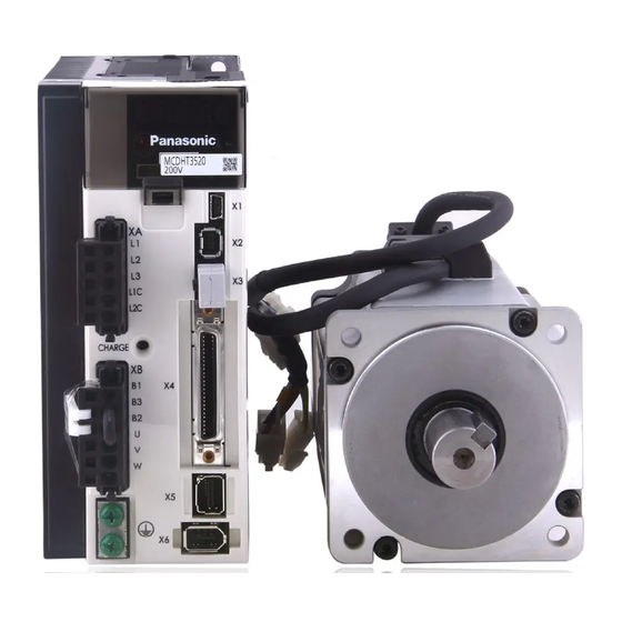
* This product image is 100 W 200 V type of A6 series.
•
Thank you for purchasing this Panasonic product.
•
Before operating this product, please read the instructions carefully, and save this manual for future use.
•
Read the the Safety Operating Instructions before using the products (P.6 to 9).
•
This product is for industrial equipment. Don't use this product at general household.
Buy: www.ValinOnline.com | Phone 844-385-3099 | Email: CustomerService@valin.com
Operating Instructions (Overall)
AC Servo Motor & Driver
MINAS A6 series
Advertisement
Chapters
Table of Contents

Related Manuals for Panasonic MINAS A6 Series


Summary of Contents for Panasonic MINAS A6 Series
- Page 1 MINAS A6 series * This product image is 100 W 200 V type of A6 series. • Thank you for purchasing this Panasonic product. • Before operating this product, please read the instructions carefully, and save this manual for future use.
- Page 2 Thank you for purchasing Digital AC Servo Motor & Driver, MINAS A6 series. This instruction manual contains information necessary to correctly and safely use the MINAS A6 series motor and driver. By reading this instruction manual, you will learn how to...
- Page 3 Organization of this manual Before Using the Products Check of the Driver Model ... Installation Describes how to identify and select the desired product and components, how to read the specifications, and how to install the equipment. Preparation Operating requirements and procedure Shows the timing chart and the list of parameters, and describes how to make wiring and to use the front panel.
-
Page 4: Table Of Contents
Contents page Organization of this manual .................... 3 Safety Precautions ......................6 Conformance to international standards ..............10 Maintenance and Inspections ..................11 1. Before Using the Products ..............1-1 1. Introduction ....................... 1-2 2. Driver ........................1-4 3. Motor ........................1-16 4. - Page 5 page 4. Setup ........................4-1 1. Describes parameters ....................4-2 2. JOG running ......................4-86 5. Adjustment ......................5-1 1. Gain Adjustment ....................... 5-2 2. Real-Time Auto-Gain Tuning ..................5-4 3. Adaptive Filter ......................5-27 4. Manual Auto-Gain Tuning (Basic) ................5-30 5.
- Page 6 Safety Precautions Please observe safety precautions fully. The following explanations are for things that must be observed in order to prevent harm to people and damage to property. • Misuses that could result in harm or damage are shown as follows, classified according to the degree of potential harm or damage.
- Page 7 In the case of the motor with shaft end keyway, do not touch the keyway with bare hands. Failure to observe this instruc- Do not touch the rotating portion of the motor tion could result in personal while it is running. injury.
- Page 8 Safety Precautions Please observe safety precautions fully. Caution Do not hold the motor cable or motor shaft during Failure to observe this instruc- the transportation. tion could result in injuries. Failure to observe this instruc- Don't drop or cause topple over of something dur- tion could result in injuries and ing transportation or installation.
- Page 9 Make an appropriate mounting of the Product Failure to heed these require- matching to its wight and output rating. ments will result in personal Observe the specified mounting method and di- injury or malfunction. rection. Use the eye bolt of the motor for transportation of Using it for transportation of the the motor only, and never use this for transporta- machine will cause personal...
- Page 10 Pursuant to the directive 2004/108/EC, article 9(2) : Europaischen Normen Panasonic Testing Centre EMC : Electromagnetic Compatibility Panasonic Service Europe, a division of : Underwriters Laboratories Panasonic Marketing Europe GmbH Winsbergring 15, 22525 Hamburg, F.R. Germany CSA : Canadian Standards Association •...
- Page 11 Maintenance and Inspections Routine maintenance and inspection of the driver and motor are essential for the proper and safe operation. Notes on Maintenance and Inspection 1) Turn on and turn off should be done by operators or inspectors themselves. When es- tablishing a system using safety functions, completely understand the applicable safety standards and the operating instruction manual or technical documents for the product.
- Page 12 Maintenance and Inspections Guideline for Parts Replacement Use the table below for a reference. Parts replacement cycle varies depending on the ac- tual operating conditions. Defective parts should be replaced or repaired when any error have occurred. Disassembling for inspection and repair should be carried out only by authorized dealers or service company.
-
Page 13: Before Using The Products
. Before Using the Products 1. Introduction Outline ......................1-2 On Opening the Product Package ...............1-3 2. Driver Check of the Model ..................1-4 Parts Description A to B-frame....................1-5 C to D-frame .....................1-5 E-frame .....................1-6 F-frame .....................1-6 Specifications....................1-7 Block Diagram ...................1-14 3. Motor Check of the Model ..................1-16 Parts Description ..................1-18 4. -
Page 14: Introduction
Before Using Outline the Products MINAS A6 series AC Servo Motor & Drivers are the brand new servo system that fulfills all requirements from various types of machines such as high-speed, high- precision, high performance and easy setup and adjustment. -
Page 15: Outline
1. Introduction Outline The standard type, communication type and multi-function type with the following different specifications. Multi-function Type Standard Type Communication Type (SE) (SG) (SF) Function Standard Type Communication Type Multi-function Type ○ ○ ○ USB communication ○ ○ Absolute system ○... -
Page 16: Driver
2. Driver Before Using Check of the Model the Products Contents of Name Plate Serial Number Model number AC SERVO DRIVER e.g.) : P15 1 0 0001N MADLT15SF Model No. Input/output voltage Lot number Serial No. P15100001N INPUT OUTPUT Number of phase Month of production 200-240 V 0-240 V... -
Page 17: Parts Description
2. Driver Before Using Parts Description the Products A to B-frame Charge lamp Front panel Connector XA: for main power connection 05JFAT-SAXGGKK-A (JST) Connector X1: USB connector Main power Connector X2: for Serial bus input terminals Connector X3: Safety function connector Control power input terminals Connector X4:... -
Page 18: E-Frame
2. Driver Parts Description E-frame Charge lamp Connector XA: for main power connection Front panel 05JFAT-SAXGSA-L(JST) Connector X1: USB connector Main power input terminals Connector X2: for Serial bus Control power Connector X3: Safety function connector input terminals Terminals for external Connector X4: Parallel I/O connector regenerative resistor (Normally short-circuit... -
Page 19: Specifications
2. Driver Before Using Specifications the Products (Multi-function type) +10 % Main circuit Single phase, 100 V to 120 V 50 Hz/60 Hz –15 % 100 V +10 % Control circuit Single phase, 100 V to 120 V 50 Hz/60 Hz –15 % A to +10 %... - Page 20 2. Driver Specifications (The Mutifuction type) Deviation counter clear, command pulse input inhibition, command division/multiplication Control input switching, vibration suppression control switching, etc. Control output Positioning complete, etc. Max. command Exclusive interface for Photocoupler and line driver: 500 kpulse/s pulse frequency Exclusive interface for line receiver: 8 Mpulse/s Input pulse signal Differential input.
- Page 21 2. Driver Specifications (The Mutifuction type) Control input Speed zero clamp, torque command sign input, etc. Control output Speed arrival, etc. Torque command input can be provided by means of analog voltage. Analog Torque command input input Parameters are used for scale setting and command polarity. (6 V/rated torque Default) Speed limit function Speed limit value with parameter t is enabled.
- Page 22 2. Driver Before Using Specifications the Products (Communication type) +10 % Main circuit Single phase, 100 V to 120 V 50 Hz/60 Hz –15 % 100 V +10 % Control circuit Single phase, 100 V to 120 V 50 Hz/60 Hz –15 % A to +10 %...
- Page 23 2. Driver Specifications (The Communication type) Over-voltage, under-voltage, over-speed, over-load, Hard error Protective over-heat, over-current and encoder error etc. function Soft error Excess position deviation, command pulse division error, EEPROM error etc. Traceability of alarm data The alarm data history can be referred to. Infinite rotation absolute function Available Deterioration diagnosis waring function...
- Page 24 2. Driver Before Using Specifications the Products (Standard type) +10 % Main circuit Single phase, 100 V to 120 V 50 Hz/60 Hz –15 % 100 V +10 % Control circuit Single phase, 100 V to 120 V 50 Hz/60 Hz –15 % A to +10 %...
- Page 25 2. Driver Specifications (The Standard type) Over-voltage, under-voltage, over-speed, over-load, Hard error Protective over-heat, over-current and encoder error etc. function Soft error Excess position deviation, command pulse division error, EEPROM error etc. Traceability of alarm data The alarm data history can be referred to. Infinite rotation absolute function Available Deterioration diagnosis waring function...
-
Page 26: Block Diagram
2. Driver Before Using Block Diagram the Products A, B-frame (100 V/200 V) Fuse Fuse Vo tage detection Fuse Gate drive DC/DC Internal voltage Front panel Current detection Serial Safety function Control curcuit Alarm signal Encoder signal Pulse train command processing Analog velocity command Control input... - Page 27 2. Driver Block Diagram E-frame (200 V) Fuse Resister Fuse Voltage detection Fuse DC/DC Internal Gate drive voltage Front panel Current detection Serial Safety function Control curcuit Alarm signal Encoder signal Pulse train command processing Analog velocity command Control input Feedback scale Control output signal processing...
-
Page 28: Motor
3. Motor Before Using Check of the Model the Products Contents of Name Plate Serial Number Model e.g.) : 15 1 00001N MSMF5AZL1A1 Rated input voltage/current Lot number 15100001N 20151001 Month of production Rated output Year of production (Lower 2 digits of AD year) Rated frequency Manufacture date e.g.) : 2015 1 001... - Page 29 3. Motor Before Using Check of the Model the Products Contents of Name Plate Motor structure MQMF、MHMF(Below □80) Symbol Shaft Holding brake Oil seal Motor I/F Key way With Connector Leadwire Without With Without With Round type type (Protective lip) Threaded ●...
-
Page 30: Parts Description
3. Motor Before Using Parts Description the Products 50 W to 1.0 kW( □ 80 ) • MSMF • MQMF 100 W to 400 W 50 W to 1.0 kW( □ 80 ) • MHMF [with Brake] Connector for encoder Connector for brake Connector for encoder Connector for motor... -
Page 31: Check Of The Combination Of The Driver And The Motor
4. Check of the Combination of the Driver and the Motor Before Using Absolute Specifications, 23-bit the Products This driver is designed to be used in a combination with the motor which are specified by us. Check the series name of the motor, rated output torque, voltage specifications and encoder specifications. -
Page 32: Installation
5. Installation Before Using Driver the Products Install the driver properly to avoid a breakdown or an accident. Installation Place 1) Install the driver in a control panel enclosed in noncombustible material and placed in- door where the product is not subjected to rain or direct sunlight. The products are not waterproof. - Page 33 5. Installation Driver Mounting Direction and Spacing • Reserve enough surrounding space for effective cooling. • Install fans to provide uniform distribution of temperature in the control panel. • D to F-frame is provided with a cooling fan at the bottom. •...
- Page 34 5. Installation Driver • Be sure to conduct wiring properly and securely. Insecure or improper wiring may cause the mo- tor running out of control or being damaged from overheating. In addition, pay attention not to al- low conductive materials, such as wire chips, entering the driver during the installation and wiring. •...
- Page 35 5. Installation Driver Relationship between Wire Diameter and Permissible Current • When selecting a cable, refer to the following selection guide showing relationship be- tween cable specification and current carrying capacity. Example: Power supply 3-phase, 200 V, 35 A, ambient temperature 30 °C Determine the fundamental permissible current according to the •...
- Page 36 5. Installation Before Using Motor the Products Install the motor properly to avoid a breakdown or an accident. Installation Place Since the conditions of location affect a lot to the motor life, select a place which meets the conditions below. 1) Indoors, where the products are not subjected to rain or direct sun beam.
-
Page 37: Motor
5. Installation Motor Oil/Water Protection 1) Don't submerge the motor cable to water or oil. 2) Install the motor with the cable outlet facing downward. 3) Avoid a place where the motor is always subject- Motor Cable ed to oil or water. 4) Use the motor with an oil seal when used with the gear reducer, so that the oil may not enter to the Oil / Water... - Page 38 5. Installation Motor Wiring Precautions on Movable Section When wiring cable bear, take the following precautions: • Cable bear wiring The bend radius of the cable must be 10 times or more its finish outside diameter. (For finish outside diameter, refer to P.1-19 How to Install, “Relationship between Wire Diameter and Permissible Current”...
-
Page 39: Permissible Load At Output Shaft
6. Permissible Load at Output Shaft Before Using Motor the Products Radial load (P) direction Thrust load (A and B) direction Unit : N (1 kgf=9.8 N) At assembly During running Motor Thrust load Thrust load A Motor output series Radial thrust Radial thrust A-direction B-direction... -
Page 40: Permissible Load At Output Shaft Motor
6. Permissible Load at Output Shaft Motor Formula of Load Formula of Load Motor Motor Motor Motor and load point and load point series output series output relation relation 3533 26754 50 W 850 W~1.8 kW L+39 L+11.5 4905 63504 100 W 2.4 kW L+59... -
Page 41: Preparation
. Preparation 1. Conformance to standards Standards ....................2-2 Composition of Peripheral Equipments ............2-4 2. System Configuration and Wiring Driver and List of Applicable Peripheral Equipments .......2-10 A to B-frame, 100 V/200 V type: ........2-12 Overall Wiring/ Wiring of the Main Circuit/ Wiring Diagram C to D-frame, 100 V/200 V type: ........2-16 Overall Wiring/ Wiring of the Main Circuit/ Wiring Diagram... -
Page 42: Conformance To International Standards
1. Conformance to international standards About confomance to internationl standards Preparation EC Directives The AC servos meet the relevant EC Directives for Low Voltage Equipment so that the machine or equipment comprising our AC servos can meet EC Directives. EMC Directives MINAS Servo System conforms to relevant standard under EMC Directives setting up certain model (condition) with certain locating distance and wiring of the servo motor and the driver. -
Page 43: Standards
Pursuant to the directive 2004/108/EC, article 9(2) : Europaischen Normen Panasonic Testing Centre EMC : Electromagnetic Compatibility Panasonic Service Europe, a division of : Underwriters Laboratories Panasonic Marketing Europe GmbH CSA : Canadian Standards Association Winsbergring 15, 22525 Hamburg, F.R. Germany •... -
Page 44: Composition Of Peripheral Equipments
1. Conformance to international standards Composition of Peripheral Equipments Preparation Installation Environment Use the servo driver in the environment of Pollution Degree 1 or 2 prescribed in IEC- 60664-1 (e.g. Install the driver in control panel with IP54 protection structure.) 100 V/200 V Metaric control box Driver... - Page 45 1. Conformance to international standards Composition of Peripheral Equipment Ferrite coil Option Manufacturer's Symbol Cable Name Amp. frame symbol Manufacturer Qty. part No. part No. (100 V)C (200 V)C, D Power cable (100 V)A, B (200 V)A, B, E DV0P1460 ZCAT3035-1330 TDK Corp.
- Page 46 1. Conformance to international standards Composition of Peripheral Equipments Power Supply 100 V type: +10 % +10 % Single phase, 100 V to 120 V 50 Hz/60 Hz –15 % –15 % (A to C-frame) 200 V type: +10 % +10 % Single/3-phase, 200 V to 240 V...
- Page 47 1. Conformance to international standards Composition of Peripheral Equipments Noise Filter Voltage specifications Manufacturer’s Applicable Option part No. Manufacturer for driver part No. driver (frame) DV0P4170 Single phase 100 V/200 V SUP-EK5-ER-6 A, B-frame 3-phase 200 V A, B-frame DV0PM20042 3SUP-HU10-ER-6 Single phase 100 V/200 V C-frame...
- Page 48 1. Conformance to international standards Composition of Peripheral Equipments Surge Absorber Voltage specifications Manufacturer’s Option part No. Manufacturer for driver part No. DV0P1450 3-phase 200 V R・A・V-781BXZ-4 Okaya Electric Ind. DV0P4190 Single phase 100 V/200 V R・A・V-781BWZ-4 Remarks When performing withstand voltage test of machine and equipment, be sure to remove the surge absorber;...
- Page 49 1. Conformance to international standards Composition of Peripheral Equipments Structure of control board If there is a gap at cable inlet/outlet, mounting hole of operation panel or a door, radio waves will penetrate into or radiate out through the gap. To prevent unfavorable condi- tions due to radio frequency activities, observe the following control board design and selection instruction.
-
Page 50: System Configuration And Wiring
2. System Configuration and Wiring Driver and List of Applicable Peripheral Equipments Preparation List of Peripheral Equipments Rated operating Noise Surge Required Circuit Noise current of magnetic Rated filter absorber Power breaker Driver Voltage filter for contactor Contact output at the rated Single phase Single phase... - Page 51 2. System Configuration and Wiring Driver and List of Applicable Peripheral Equipments Diameter Crimp Diameter Crimp Diameter terminal Diameter Required terminal withstand for control Voltage Rated withstand for main withstand Power Driver voltage power withstand voltage of circuit voltage of output at the of control...
- Page 52 2. System Configuration and Wiring Overall Wiring (A to B-frame, 100 V/200 V type) Preparation Connecting Example of A to B-frame • Apply the voltage designated on the Mains nameplate from the power source. Residual current device Symmetric current should be 5000 Arms or below. If the short-circuit current on the power source exceeds this value, use a current-limiting device (e.g.
- Page 53 2. System Configuration and Wiring Overall Wiring (A to B-frame, 100 V/200 V type) : High voltage PC (to be supplied by customer) Handle lever Use this for connector connection. Store this after connection for Setup support software “PANATERM” other occasions. Please download from our web site.
-
Page 54: A To B-Frame, 100 V/200 V Type
2. System Configuration and Wiring Wiring of the Main Circuit (A to B-frame, 100 V/200 V type) Preparation A to B-frame, 100 V / 200 V type • Wiring should be performed by a specialist or an authorized personnel. • Do not turn on the power until the wiring is completed. •... -
Page 55: Connection
2. System Configuration and Wiring Wiring Diagram (A to B-frame, 100 V/200 V type) Preparation Compose the circuit so that the main circuit power will be shut off when an error occurs. However, if you want to use “immediate stop function” and the main circuit power turns off, please be aware that you will no longer be able to use “immediate stop function”. - Page 56 2. System Configuration and Wiring Overall Wiring (C to D-frame, 100 V/200 V type) Preparation Connecting Example of C to D-frame • Apply the voltage designated on the nameplate Mains from the power source. Residual current device Symmetric current should be 5000 Arms or below. If the short-circuit current on the power source exceeds this value, use a current-limiting device (e.g.
- Page 57 2. System Configuration and Wiring Overall Wiring (C to D-frame, 100 V/200 V type) : High voltage PC (to be supplied by customer) Handle lever Use this for connector connection. Store this Setup support software “PANATERM” after connection for Charge lamp Please download from our web site.
-
Page 58: C To D-Frame, 100 V/200 V Type
2. System Configuration and Wiring Wiring of the Main Circuit (C to D-frame, 100 V/200 V type) Preparation C to D-frame, 100 V / 200 V type • Wiring should be performed by a specialist or an authorized personnel. • Do not turn on the power until the wiring is completed. •... - Page 59 2. System Configuration and Wiring Wiring Diagram (C to D-frame, 100 V/200 V type) Preparation Compose the circuit so that the main circuit power will be shut off when an error occurs. However, if you want to use “immediate stop function” and the main circuit power turns off, please be aware that you will no longer be able to use “immediate stop function”.
- Page 60 2. System Configuration and Wiring Overall Wiring (E-frame, 200 V type) Preparation Connecting Example of E-frame • Apply the voltage designated on the nameplate Mains from the power source. Residual current device Symmetric current should be 5000 Arms or below. If the short-circuit current on the power source exceeds this value, use a current-limiting device (e.g.
- Page 61 2. System Configuration and Wiring Overall Wiring (E-frame, 200 V type) : High voltage PC (to be supplied by customer) Handle lever Use this for connector connection. Store this Charge lamp Setup support software “PANATERM” after connection for (Red LED) Please download from our web site.
- Page 62 2. System Configuration and Wiring Wiring of the Main Circuit (E-frame, 200 V type) Preparation E-frame, 200 V type • Wiring should be performed by a specialist or an authorized personnel. • Do not turn on the power until the wiring is completed. •...
- Page 63 2. System Configuration and Wiring Wiring Diagram (E-frame, 200 V type) Preparation Compose the circuit so that the main circuit power will be shut off when an error occurs. However, if you want to use “immediate stop function” and the main circuit power turns off, please be aware that you will no longer be able to use “immediate stop function”.
- Page 64 2. System Configuration and Wiring Overall Wiring (F-frame, 200 V type) Preparation Connecting Example of F-frame • Apply the voltage designated on the nameplate Mains from the power source. Residual current device Symmetric current should be 5000 Arms or below. If the short-circuit current on the power source exceeds this value, use a current-limiting device (e.g.
- Page 65 2. System Configuration and Wiring Overall Wiring (F-frame, 200 V type) : High voltage PC (to be supplied by customer) Setup support software “PANATERM” Please download from our web site. Charge lamp (Red LED) Wiring to Connector, X1 P.2-32 • Connection to PC (PANATERM) Wiring to Connector, X2 P.2-32 •...
- Page 66 2. System Configuration and Wiring Wiring of the Main Circuit (F-frame, 200 V type) Preparation F-frame, 200 V type • Wiring should be performed by a specialist or an authorized personnel. • Do not turn on the power until the wiring is completed. •...
- Page 67 2. System Configuration and Wiring Wiring Diagram (F-frame, 200 V type) Preparation Compose the circuit so that the main circuit power will be shut off when an error occurs. However, if you want to use “immediate stop function” and the main circuit power turns off, please be aware that you will no longer be able to use “immediate stop function”.
-
Page 68: Specifications Of Motor Connector
2. System Configuration and Wiring Specifications of Motor connector Preparation When leadwire type was be used • When the motors of <MSMF, MQMF, MHMF> are used, they are connected as shown below. Connector: Made by Tyco Electronics k.k, (The figures below show connectors for the motor.) PIN No. - Page 69 2. System Configuration and Wiring Specifications of Motor connector MHMF(50 W, 100 W) PIN No. Application U-phase Connector for motor V-phase W-phase Ground Tightening torque of the screw (M2) 0.085 N·m to 0.095 N·m JN11AH06NN2 (screwed to plastic) * Be sure to use only the screw supplied with the connector, to avoid damage.
- Page 70 2. System Configuration and Wiring Specifications of Motor connector (1.0 kW(□100) to 5.0 kW) , MDMF, MGMF, MHMF (1.0 kW(□130) to 5.0 kW) • When the motors of <MSME > are used, they are connected as shown below. Connector: Made by Japan Aviation Electronics Industry, Ltd. (The figures below show connectors for the motor.) •...
-
Page 71: Wiring Method To Connector
2. System Configuration and Wiring Wiring method to connector Preparation • Follow the procedures below for the wiring connection to the Connector How to connect 1. Peel off the insulation cover of the cable. 8 to 9 mm • For single wire (Please obey the length in figure.) •... -
Page 72: Wiring To The Connector, X1
3. Wiring to the connector, X1 Connecting host computer Preparation ○ ○ ○ This is used for USB connection to a personal computer. It is possible to change the pa- rameter setting and perform monitoring. Connector Application Symbol Contents Pin No. VBUS Use for communication with personal D−... - Page 73 4. Wiring to the connector, X2 Connecting host computer • This servo driver features 2 kinds of communication function, RS232 and RS485, and you can use in 3 connecting methods. To communicate with a single driver through RS232 Connect the host (PC or controller) to an driver through RS232. [How to connect] Shut off both powers of Cable prepared...
-
Page 74: Wiring To The Connector, X3
5. Wiring to the connector, X3 Safety function connector Preparation ○ A safety by-pass plug is supplied as standard equipment. Do not disconnect it in normal times. When controlling the safety function from the connected host controller, accessory con- nector cannot be used. Prepare and wire the connector (option) as specified below. Since the standard connector cannot be used when controlling the safety function from the host controller, purchase the optional connector and make connection as shown be- low. -
Page 75: Wiring To The Connector, X4
6. Wiring to the connector, X4 Connection to Host Controller Preparation Tips on wiring Peripheral apparatus such as host controller should be located or shorter within 3 m. Controller 30 cm or longer Separate the main circuit at least 30 cm away. Power supply Don't pass them in the same duct, nor bind them together. -
Page 76: Wiring To The Connector, X5
7. Wiring to the connector, X5 Connect on to External Scale Preparation ○ Provide a power supply for the external scale on your part or use the following power out- put (250 mA or less). Connector Application Symbol Contents Pin No. Supply the power of external scale or A, B, EX5V Power supply... - Page 77 7. Wiring to the connector, X5 Connect on to Feedback Scale Wiring Diagram of X5 Connec or X5 +5 V EX5V EX5V EX0V EX0V EXPS EXPS EXPS EXPS Twisted pair MUF PK10K X (J S T Mfg Co L d ) Shell of X5 (FG) Detection head Junction cable...
-
Page 78: Wiring To The Connector, X6
8. Wiring to the connector, X6 Connection to Encoder Preparation ○ ○ ○ Tips on Wiring Maximum cable length between the driver and the motor to be Power 20 m. Consult with a dealer or distributor if you want to use supply the longer cable than 20 m. - Page 79 8. Wiring to the connector, X6 Connection to Encoder Wiring Diagram • In case of 23-bit absolute encoder (as mutli-turn data was be used ) ● MSMF 50 W to 1.0 kW( □80 ), ●MQMF 100 W to 400 W, ● MHMF 50 W to 1.0 kW( □80 ) Leadwire type White +5 V...
- Page 80 8. Wiring to the connector, X6 Connection to Encoder Wiring Diagram • In case of 23-bit absolute encoder (as single turn data was be used ) ● MSMF 50 W to 1.0 kW( □80 ), ●MQMF 100 W to 400 W, ● MHMF 50 W to 1.0 kW( □80 ) White Leadwire type +5 V...
-
Page 81: Timing Chart
9. Timing Chart Timing on power-up Preparation Servo-on signal accept timing on power-up Control power supply (L1C,L2C) approx.100 ms to 300 ms Internal control established power supply approx.2 s approx.1.5 s Action of reset (initialization) usually operation driver CPU 0 s or longer Main power supply (L1,L2,L3) -
Page 82: Alarm
9. Timing Chart Alarm Preparation When an Error (Alarm) Has Occurred (at Servo-ON Command) ● DB/Free run deceleration operation Alarm normal alarm output Tr OFF Servo on status output Tr ON Servo on status off output(SRV-ST) Servo on status on 0.5 ms to 5 ms Dynamic brake engaged *2... -
Page 83: Servo-Lock
9. Timing chart Alarm When an Alarm Has Been Cleared (at Servo-ON Command) 120 ms or longer *1 Alarm-clear input input coupler input coupler input coupler ON (A-CLR) engaged approx.2 ms released Dynamic brake Servo on status approx.25 ms output(SRV-ST) approx.60 ms not-energized energized... -
Page 84: Servo-On/Off
9. Timing Chart Servo-ON/OFF Preparation Servo-ON/OFF Action While the Motor Is in Motion Remarks Timing at emergency stop or trip. Do not repeat this sequence. at Servo-ON at Servo-OFF Servo-ON input input coupler input coupler input coupler ON (SRV-ON) 1 to 5 ms Dynamic brake engaged *3 released... -
Page 85: Built-In Holding Brake Outline
10. Built-in Holding Brake Outline Preparation In the applications where the motor drives the vertical axis, this brake would be used to hold and prevent the work (moving load) from falling by gravity while the power to the servo is shut off. Caution Use this built-in brake for "Holding"... -
Page 86: Specifications
10. Built-in Holding Brake Specifications Preparation Static Exciting Permissible Rotor Engaging Releasing Permissible Permissible Motor Motor friction current Releasing angular inertia time time work (J) per total work series output torque DC A voltage acceleration x 10 kg·m one braking x 10 –4 N·m... -
Page 87: Dynamic Brake
11. Dynamic Brake Outline Preparation This driver (A to F-frame) is equipped with a dynamic brake for emergency stop. Pay a special attention to the followings. 1. Dynamic brake is only for emergency stop. Caution Do not start/stop the motor by turning on/off the Servo-ON signal (SRV-ON). Otherwise it may damage the dynamic brake circuit of the driver. -
Page 88: Condition Setting Chart
11. Dynamic Brake Condition setting chart Preparation 1) Setup of driving condition from deceleration to after stop by main power-off (Pr5.07) Contents of Driving condition Sequence at main deviation power-off (Pr5.07) During deceleration After stalling counter Setup value of Pr5.07 Clear Free-run Clear... - Page 89 12. Dynamic Brake Condition setting chart 3) Setup of driving condition from deceleration to after stop by activation of protective function (Pr5.10) Contents of Driving condition Sequence at over-travel deviation inhibit input (Pr5.10) During deceleration After stalling counter Setup value of Pr5.10 Hold Free-run Hold...
-
Page 90: Setup Of Parameter And Mode
12. Setup of Parameter and Mode Outline / Setup / Connection Preparation Outline of Parameter This driver is equipped with various parameters to set up its characteristics and functions. This section describes the function and purpose of each parameter. Read and compre- hend very well so that you can adjust this driver in optimum condition for your running requirements. -
Page 91: Composition And List Of Parameters
12. Setup of Parameter and Mode Composition and List of Parameters Preparation • The parameter No. is displayed in the form of PrX.YY (X: Classification, YY: No.). • For the details on the parameters, refer to P.4-4 “Details of parameter”. Parametr No. -
Page 92: List Of Parameters
12. Setup of Parameter and Mode List of Parameters Preparation [Class 0] Basic setting Parametr Related Turning Default Control Mode Detail on of Title Range Unit power page D,E,F Class No. P S T supply -frame -frame -frame ○ ○ ○ ○ ○ Rotational direction setup 0 to 1 −... - Page 93 12. Setup of Parameter and Mode List of Parameters Parametr Turning Related Default on of Control Mode Detail Title Range Unit power page D,E,F Class No. P S T supply -frame -frame -frame ○ ○ ○ ○ 1st filter of speed detection 0 to 5 −...
- Page 94 12. Setup of Parameter and Mode List of Parameters Parametr Turning Related Default on of Control Mode Detail Title Range Unit power page D,E,F P S T Class No. supply -frame -frame -frame For manufactuer's use − − For manufactuer's use −...
- Page 95 12. Setup of Parameter and Mode List of Parameters Parametr Turning Related Default on of Control Mode Detail Title Range Unit power page D,E,F P S T Class No. supply -frame -frame -frame For manufactuer's use − 1000 − For manufactuer's use −...
- Page 96 12. Setup of Parameter and Mode List of Parameters Parametr Turning Related Default on of Control Mode Detail Title Range Unit power page D,E,F P S T Class No. supply -frame -frame -frame 0 to 99 ○ ○ ○ ○ 2nd notch depth selection −...
- Page 97 12. Setup of Parameter and Mode List of Parameters Parametr Turning Related Default on of Control Mode Detail Title Range Unit power page D,E,F P S T Class No. supply -frame -frame -frame For manufactuer's use − − For manufactuer's use −...
- Page 98 12. Setup of Parameter and Mode List of Parameters Parametr Turning Related Default on of Control Mode Detail Title Range Unit power page D,E,F P S T Class No. supply -frame -frame -frame ○ Speed limit value 2 0 to 20000 r/min 4-36 ○...
- Page 99 12. Setup of Parameter and Mode List of Parameters Parametr Turning Related Default on of Control Mode Detail Title Range Unit power page D,E,F Class No. P S T supply -frame -frame -frame ○ ○ ○ ○ Type of analog monitor 1 0 to 28 −...
- Page 100 12. Setup of Parameter and Mode List of Parameters Parametr Turning Related Default on of Control Mode Detail Title Range Unit power page D,E,F Class No. P S T supply -frame -frame -frame − ○ ○ ○ Position compare output polarity select 0 to 63 −...
- Page 101 12. Setup of Parameter and Mode List of Parameters Parametr Turning Related Default on of Control Mode Detail Title Range Unit power page D,E,F Class No. P S T supply -frame -frame -frame ○ ○ ○ ○ Over-load level setup 0 to 500 ○...
- Page 102 12. Setup of Parameter and Mode List of Parameters Parametr Turning Related Default on of Control Mode Detail Title Range Unit power page D,E,F Class No. P S T supply -frame -frame -frame For manufactuer's use − − 4-62 -32768 to ○...
- Page 103 12. Setup of Parameter and Mode List of Parameters Parametr Turning Related Default on of Control Mode Detail Title Range Unit power page D,E,F Class No. P S T supply -frame -frame -frame Deterioration diagnosis unbalanced load -1000 to ○ ○...
- Page 104 12. Setup of Parameter and Mode List of Parameters Parametr Turning Related Default on of Control Mode Detail Title Range Unit power page D,E,F P S T Class No. supply -frame -frame -frame ○ ○ 4-68 Position control 3rd gain scale factor 50 to 1000 ○...
- Page 105 12. Setup of Parameter and Mode List of Parameters Parametr Turning Related Default on of Control Mode Detail Title Range Unit power page D,E,F Class No. P S T supply -frame -frame -frame ○ ○ ○ ○ ○ Alarm mask setup −32768 to 32767 −...
- Page 106 12. Setup of Parameter and Mode List of Parameters Parametr Turning Related Default on of Control Mode Detail Title Range Unit power page D,E,F P S T Class No. supply -frame -frame -frame ○ ○ ○ Load estimation filter 0 to 2500 0.01 ms ○...
- Page 107 12. Setup of Parameter and Mode List of Parameters Parametr Related Turning Default Control Mode Detail on of Title Range Unit power page D,E,F Class No. P S T supply -frame -frame -frame For manufacturer's use − − -32768 to Special function enhancement setting 1 −...
- Page 108 12. Setup of Parameter and Mode List of Parameters Parametr Related Turning Default Control Mode Detail on of Title Range Unit power page D,E,F P S T Class No. supply -frame -frame -frame For manufacturer's use − − For manufacturer's use −...
- Page 109 12. Setup of Parameter and Mode List of Parameters Parametr Related Turning Default Control Mode Detail on of Title Range Unit power page D,E,F P S T Class No. supply -frame -frame -frame For manufacturer's use − − For manufacturer's use −...
-
Page 110: Setup Of Torque Limit
12. Setup of Parameter and Mode Setup of Torque Limit Preparation Torque limit setup range is 0 to 300 and default is 300 except the combinations of the motor and the driver listed in the table below. Max. value of Frame Model No. - Page 111 12. Setup of Parameter and Mode Setup of Torque Limit Cautions on Replacing the Motor As stated previously, torque limit setup range might change when you replace the combi- nation of the motor and the driver. Pay attention to the followings. 1.
-
Page 112: Setup Of Command Division And Multiplication Ratio (Electronic Gear Ratio)
Setup of command division and multiplication ratio (electronic gear ratio) Preparation Relation between Electronic Gear and Position Resolution or Traveling Speed Driver Electronic gear ratio Rotational speed : N[r/min] Pulse train position command Pr0.09 Motor Gear Machine Pr0.10 Travel distance : P1 [P] –... - Page 113 13. Setup of command division and multiplication ratio (electronic gear ratio) Relation between Electronic Gear and Position Resolution or Traveling Speed ∆M×E×R Pr0.09 Electronic gear ratio Pr0.10 Lead of ball screw, L =10 mm Gear reduction ratio, R = 1 0.0005×2 ×1 5×2...
-
Page 114: How To Use The Front Panel
14. How to Use the Front Panel Setup Preparation Setup with the Front Panel Display LED (6-digit) Switch to error display screen when error occurs, and LED will flash (about 2 Hz). LED will flash slowly (about 1 Hz) when warning occurs. -
Page 115: How To Use The Front Panel Setup
14. How to Use the Front Panel Setup Initial Status of the Front Panel Display (7 Segment LED) Status Front panel display shows the following after turning on the power of the driver. approx. 2 sec approx. 0.6 sec approx. 0.6 sec Initial display of LED (Determined by the setup of Parameter, Pr5.28 "Initial status of LED".) Upon Occurrence of an Alarm... -
Page 116: Structure Of Each Mode
14. How to Use the Front Panel Structure of Each Mode Preparation Use each button on the touch panel to select the structure and switch the mode. SELECTION display Monitor mode Initial status of P.2-80 (SET button) the Console LED (Mode switching button) Parameter set up mode... - Page 117 14. How to Use the Front Panel Structure of Each Mode EXECUTION display ..P.2-81 to 95 (SET button) ..P.2-95 • For details of parameters, refer to (SET button) P.4-2 "Details of parameter"..P.2-97 (SET button) ..P.2-99 • Alarm clear ..P.2-100 •...
-
Page 118: Setup Of Front Panel Lock
14. How to Use the Front Panel Setup of front panel lock Preparation Outline To prevent operational error e.g. unintentional parameter modification, the front panel may be locked. Once locked, operations on the panel are limited as follows: Mode Locked panel conditions Monitor Mode No limitation: all monitored data can be checked. -
Page 119: Exclusive Functions By Operations Performed By Communications
14. How to Use the Front Panel Exclusive functions by operations performed by communications Preparation Outline To prevent operations by communication (USB/RS232/RS485/Modbus) and operation from the front panel being in conflict with each other, the following exclusive functions will be triggered depending on their respective state: Mode Locked panel conditions Parameter write and EEPROM write by... -
Page 120: Monitor Mode (Selection Display)
14. How to Use the Front Panel Monitor Mode (SELECTION display) Preparation To change the monitor display setting, select the display option to be changed from “ SELECTION display”, and press to change to “ EXECUTION display”. After completion of changing, press to return to the selection display, Monitor Mode SELECTION display... - Page 121 14. How to Use the Front Panel Monitor Mode (EXECUTION display) Preparation (1) Display of positional command deviation [command unit] Displays positional deviation of the command unit in High order or Low order. Positional command deviation ..Low order ..High order •...
- Page 122 14. How to Use the Front Panel Monitor Mode (EXECUTION display) (3) Display of Feedback Pulse Sum, Command Pulse Sum and External Scale Feedback Pulse Sum • Feedback Pulse Sum [Encoder feedback pulse] Feedback Pulse Sum ..Low order ..High order •...
-
Page 123: Monitor Mode (Execution Display)
14. How to Use the Front Panel Monitor Mode (EXECUTION display) (5) Display of I/O Signal Status Displays the control input and output signal to be connected to connector X4. Use this function to check if the wiring is correct or not..Active ..Inactive Pin No. - Page 124 14. How to Use the Front Panel Monitor Mode (EXECUTION display) (6) Display of Analog Input Value Input voltage value [V] Input signal •Select the signal No. to be monitored by pressings Displays the value after (Analog input 1 value, unit [V]) offset correction.
- Page 125 14. How to Use the Front Panel Monitor Mode (EXECUTION display) (7) Display of Error Factor and Reference of History Error code No. ( appears if no error occurs) • You can refer the last 14 ..Present error error factors (including ..History 0 (latest error) present one) Press...
- Page 126 14. How to Use the Front Panel Monitor Mode (EXECUTION display) Error code Attribute Protective function Can be Immediate Main History cleared stop ○ Over-travel inhibit input protection ○ ○ ○ Analog input1 excess protection ○ ○ ○ Analog input2 excess protection ○...
- Page 127 14. How to Use the Front Panel Monitor Mode (EXECUTION display) (8) Alarm Display ..No alarm occurred ..High priority alarm Alarm number • To display the alarm occurrence condition, press button. alarm Latched Alarm Content time Overload protection Load factor is 85 % or more the protection level. 1 s to 10 s or ∞...
- Page 128 14. How to Use the Front Panel Monitor Mode (EXECUTION display) (9) Display of Regenerative Load Factor, Over-load Factor and Inertia Ratio • Regenerative Load Factor Display the ratio (%) against the alarm trigger level of regenerative protection. This is valid when Pr0.16 (External regenerative resistor setup) is 0 or 1.
- Page 129 14. How to Use the Front Panel Monitor Mode (EXECUTION display) 10) Display of the Factor of No-Motor Running Displays the factor of no-motor running in number..Position control ..Torque control ..Velocity control ..Full-closed control Factor No. Control mode •...
- Page 130 14. How to Use the Front Panel Monitor Mode (EXECUTION display) (11) Display of No. of changes in I/O signals No. of changes in I/O signals (the signal is invalid) Pin No..Input signal ..Output signal • Shift the flashing decimal point with (Left side of decimal point : Pin No.
- Page 131 14. How to Use the Front Panel Monitor Mode (EXECUTION display) (13) Display of absolute external scale position • Displays the absolute position of serial absolute scale. • If a serial incremental scale, displays the scale position relative to the power on position which is defined as 0.
- Page 132 14. How to Use the Front Panel Monitor Mode (EXECUTION display) (17) Display of External Scale Deviation [External Scale Unit] External Scale Deviation [External scale unit] ..Low order ..High order • To switch between Low order (L) and High order (H), press (18) Display of hybrid deviation [Command unit] Hybrid deviation [Command unit] ..Low order...
- Page 133 14. How to Use the Front Panel Monitor Mode (EXECUTION display) (21) Display of driver serial number Driver serial number ..Driver serial number- Low order ..Driver serial number- High order • To switch between Low order (L) and High order (H), press (Example of display: Serial number P15040001N) (22) Display of motor serial number Motor serial number...
- Page 134 14. How to Use the Front Panel Monitor Mode (EXECUTION display) (25) Display of temperature Displays the driver temperature [C]. (This is not meter readings but only for reference.) Displays the encoder temperature [C]. (This is not meter readings but only for reference.) (26) Display of safety condition monitor : Safety condition : Servo-off condition...
- Page 135 14. How to Use the Front Panel Monitor Mode (EXECUTION display) (27) Motor power consumption Motor power consumption [W] Motor electrical power [Wh] Precautions) If the monitor data is displayed with lower (L) and higher (H), displays of the front panel are as follows. Example 1) Monitor data = 15000 (within the display range of lower (L)) .
-
Page 136: Parameter Setup Mode
14. How to Use the Front Panel Parameter Setup Mode Preparation SELECTION display Monitor Mode (Mode switch button) EXECUTION display Parameter Setup Mode SELECTION display You can change the value which digit has Parameter No. a flashing decimal (Hexadecimal No.) Parameter value point. -
Page 137: Eeprom Writing Mode
14. How to Use the Front Panel EEPROM Writing Mode Preparation Parameter Setup Mode SELECTION display (Mode switch button) EXECUTION display SELECTION display EEPROM Writing Mode • To write the parameter to EEPROM, press • Keep pressing until the display to change to EXECUTION display. -
Page 138: Auxiliary Function Mode Selection Display
14. How to Use the Front Panel Auxiliary Function Mode (SELECTION display) Preparation EEPROM Writing Mode SELECTION display (Mode switch button) EXECUTION display Auxiliary Function Mode SELECTION display • To select the desired auxiliary function, Display Pages to press Description example refer Alarm Clear... -
Page 139: Auxiliary Function Mode (Execution Display)
14. How to Use the Front Panel Auxiliary Function Mode (EXECUTION display) Preparation 1) Alarm Clear Screen This function releases the current alarm status. Certain alarms will persist. If this is the case, refer to P.6-2 “When in Trouble - Protective Function”. - Page 140 14. How to Use the Front Panel Auxiliary Function Mode (EXECUTION display) (2) Analog inputs 1 to 3 automatic offset adjustment This function automatically adjusts offset setting of analog input. Analog input 1 (AI1)..Pr4.22 (Analog input 1 (AI1) offset setup) Analog input 2 (AI2)..Pr4.25 (Analog input 2 (AI2) offset setup) Analog input 3 (AI3)..Pr4.28 (Analog input 3 (AI3) offset setup) EXECUTION display...
- Page 141 14. How to Use the Front Panel Auxiliary Function Mode (EXECUTION display) (3) Motor trial run You can make a trial run (JOG run) without connecting the Connector, Connector X4 to the host controller such as PLC. Remarks • Separate the motor from the load, detach the Connector, Connector X4 before the trial run.
- Page 142 14. How to Use the Front Panel Auxiliary Function Mode (EXECUTION display) • Procedure for Trial Run EXECUTION display SELECTION display • Keep pressing until the display changes to • Press to call for (SET button) when you execute Motor trial run. EXECUTION display.
- Page 143 14. How to Use the Front Panel Auxiliary Function Mode (EXECUTION display) 4) Clearing of Absolute Encoder You can clear the multi-turn data of the absolute encoder. SELECTION display EXECUTION display • Keep pressing until the display changes to (SET button) •...
- Page 144 14. How to Use the Front Panel Auxiliary Function Mode (EXECUTION display) (5) Initialization of parameter Initialize the parameter. SELECTION display EXECUTION display • Keep pressing until the display changes to (SET button) • Press to call for when you execute Initialization of parameter. EXECUTION display.
- Page 145 14. How to Use the Front Panel Auxiliary Function Mode (EXECUTION display) (6) Release of front panel lock Release the front panel lock setting. SELECTION display EXECUTION display • Keep pressing until the display changes to (SET button) • Press to call for when you execute Release of front panel lock.
- Page 146 14. How to Use the Front Panel Auxiliary Function Mode (EXECUTION display) (7) Battery refresh Battery refresh action is conducted. SELECTION display EXECUTION display • Keep pressing until the display changes to (SET button) • Press to call for when you execute battery refresh. EXECUTION display.
-
Page 147: Outline Of Mode
. Connection 1. Outline of mode Position Control Mode ................3-2 Velocity Control Mode .................3-6 Torque Control Mode ..................3-9 Full-closed Control Mode ................3-12 2. Control Block Diagram Position Control Mode (Two-degree-of-freedom control noneffective) ..3-14 Position Control Mode (Two-degree-of-freedom control effective) ...3-15 Velocity Control Mode (Two-degree-of-freedom control noneffective) ..3-16 Velocity Control Mode (Two-degree-of-freedom control effective) ...3-17 Torque Control Mode ................3-18... -
Page 148: Connection
1. Outline of mode Position Control Mode Connection ○ ○ ○ Outline You can perform position control based on the positional command (pulse train) from the host controller. This section describes the fundamental setup to be used for the position control. Pos t ona command Servo dr ver... - Page 149 1. Outline of mode Position Control Mode (2) Electronic gear function This function multiplies the input pulse command from the host controller by the pre- determined dividing or multiplying factor and applies the result to the position control section as the positional command. By using this function, desired motor rotations or movement distance per unit input command pulse can be set;...
- Page 150 1. Outline of mode Position Control Mode (4) Pulse regeneration function The information on the amount of movement can be sent to the host controller in the form of A- and B-phase pulses from the servo driver. When the output source is the encoder, Z-phase signal is output once per motor revolution;...
- Page 151 1. Outline of mode Position Control Mode (6) Positioning complete output (INP) function The completion of positioning can be verified by the positioning complete output (INP). When the absolute value of the positional deviation counter at the position control is equal to or below the positioning complete range by the parameter, the output is ON.
-
Page 152: Velocity Control Mode
1. Outline of mode Velocity Control Mode Connection ○ ○ ○ Outline You can control the speed according to the analog speed command from the host con- troller or the speed command set in the servo driver. Ana og Servo dr ver speed command Process of ana og speed command nput... - Page 153 1. Outline of mode Velocity Control Mode (2) Velocity control by internal speed command You can control the speed by using the internal speed command set to the parameter. By using the internal speed command selections 1, 2, 3 (INTSPD1, 2, 3), you can select best appropriate one among up to 8 internal speed command settings.
- Page 154 1. Outline of mode Velocity Control Mode (5) Speed coincidence output (V-COIN) This signal is output when the motor speed is equal to the speed specified by the speed command. The motor speed is judged to be coincident with the specified speed when the difference from the speed command before/after acceleration/deceleration is within the range specified by Pr4.35 “Speed coincident range”...
-
Page 155: Torque Control Mode
1. Outline of mode Torque Control Mode Connection ○ Outline The torque control is performed according to the torque command specified in the form of analog voltage. For controlling the torque, the speed limit input is required in addition to the torque command to maintain the motor speed within the speed limit. - Page 156 1. Outline of mode Torque Control Mode Function (1) Process of analog torque command input This process converts the analog torque command input (voltage) to the equivalent digital torque command having the same effect. You can set the filter or adjust the off- set to eliminate noise.
- Page 157 1. Outline of mode Torque Control Mode (2) Speed limit function The speed limit is one of protective functions used during torque control. This function regulates the motor speed so that it does not exceed the speed limit while the torque is controlled. Caution While the speed limit is used to control the motor, the torque command applied to the motor is not directly proportional to the analog torque command.
-
Page 158: Full-Closed Control Mode
1. Outline of mode Full-closed Control Mode Connection ○ Outline In this full-closed control, you can make a position control by using a external scale mounted externally which detects the position directly and feeds it back. With this control, you can control without being affected by the positional variation due to the ball screw error or temperature and you can expect to achieve a very high precision positioning in sub-micron order. - Page 159 1. Outline of mode Full-closed Control Mode 6) Set up appropriate value of hybrid deviation excess (Pr3.28) in command unit, in order to avoid the damage to the machine. * A6-series driver calculates the difference between the encoder position and the external scale position as hybrid deviation, and is used to prevent the machine runaway or damage in case of the external scale breakdown or when the motor and the load is disconnected.
-
Page 160: Control Block Diagram
2. Control Block Diagram Position Control Mode Connection (Two-degree-of-freedom control noneffective) ○ ○ ○ Sum of command pulses Positional command Internal positional [Command unit] speed [r/min] command speed [r/min] Pulse train Input setup Electric gear Smoothing Damping control PULS filter Gain switching Input SIGN... -
Page 161: Position Control Mode (Two-Degree-Of-Freedom Control Effective)
2. Control Block Diagram Position Control Mode Connection (Two-degree-of-freedom control effective) ○ ○ ○ Sum of command pulses Positional command [Command unit] speed [r/min] Pulse train Input setup Electric gear Smoothing Damping control PULS filter Input Switching SIGN 0.05 0.08 0.09 5.00 2.13... -
Page 162: Velocity Control Mode (Two-Degree-Of-Freedom Control Noneffective)
2. Control Block Diagram Internal speed Analog SE SG SF SE SG SF Velocity Control Mode Connection (2DOF control noneffective) command input ○ ○ ○ ○ Gain switching 1.14 setup 1.20 Mode Delay 1.21 time 1.22 Level Al1 input voltage [V] 1.23 Hysteresis... -
Page 163: Velocity Control Mode (Two-Degree-Of-Freedom Control Effective)
2. Control Block Diagram Internal speed Analog SE SG SF SE SG SF Velocity Control Mode Connection (2DOF control effective) command input ○ ○ ○ ○ Gain switching 1.14 setup 1.20 Mode Delay 1.21 time 1.22 Level Al1 input voltage [V] 1.23 Hysteresis... -
Page 164: Torque Control Mode
2. Control Block Diagram Torque Control Mode Connection ○ Al2 input voltage [V] Analog Gain switching input 2 1.14 Analog input Scaling 12bit A/D setup 1.24 Mode 4.25 3.19 Offset Gain Delay 1.25 time Torque command 4.26 3.20 Filter Reversal 1.26 Level selection... -
Page 165: Full-Closed Control Mode (Two-Degree-Of-Freedom Control Effective)
2. Control Block Diagram Full-closed Control Mode Connection (Two-degree-of-freedom control noneffective) ○ Internal positional command speed [r/min] External scale dividing Numera- Sum of command pulses Positional command 3.24 [Command unit] speed [r/min] Denomi 3.25 nator Pulse train Input setup Electric gear Smoothing Damping control PULS... - Page 166 2. Control Block Diagram Full-closed Control Mode Connection (Two-degree-of-freedom control effective) ○ Internal positional command speed [r/min] External scale dividing Numera- Sum of command pulses Positional command 3.24 [Command unit] speed [r/min] Denomi 3.25 nator Pulse train Input setup Electric gear Smoothing Damping control PULS...
-
Page 167: Wiring Diagram To The Connector, X4
3. Wiring Diagram to the connector, X4 Example of control mode specific wiring Connection Wiring Example of Position Control Mode ○ ○ ○ In case of open collector I/F (1) When you use the external 7 COM+ 2.2 kΩ OPC1 resistor with 12 V and 24 V Command pulse 4.7 kΩ... - Page 168 3. Wiring Diagram to the connector, X4 Example of control mode specific wiring Wiring Example of Torque Control Mode ○ 7 COM+ 4.7 kΩ Servo-ON input SRV-ON Gain switching input GAIN DIV1 Speed zero clamp input A-phase ZEROSPD Control mode output switching input C-MODE...
-
Page 169: Connecting Example To Host Controller
3. Wiring Diagram to the connector, X4 Connecting Example to Host Controller Connection Connection between MINAS A6 and FP7-AFP7PP02T/L(2-axes) AFP7PP04T/L(4-axes) Panasonic devices SUNX. Driver FP7-AFP7PP02T/L(2-axes) A6 series AFP7PP04T/L(4-axes) (Panasonic devices SUNX.) * Process of shield wire varies with equipment. 1/3-axes 2/4-axes... - Page 170 3. Wiring Diagram to the connector, X4 Connecting Example to Host Controller Connection between MINAS A6 and FPG-PP12 AFPG432 Panasonic devices SUNX. Driver FPG-PP12 AFPG432 A6 series (Panasonic devices SUNX.) * Process of shield wire varies with equipment. PULS1 Command pulse...
- Page 171 3. Wiring Diagram to the connector, X4 Connecting Example to Host Controller Connection between MINAS A6 and FP2-PP2 AFP2430 Panasonic devices SUNX. Driver FP2-PP2 AFP2430 A6 series (Panasonic devices SUNX.) * Process of shield wire varies with equipment. PULS1 CW pulse command...
- Page 172 3. Wiring Diagram to the connector, X4 Connecting Example to Host Controller Connection between MINAS A6 and FPG-C32T Panasonic devices SUNX. Driver FPG-C32T A6 series (Panasonic devices SUNX.) * Process of shield wire varies with equipment. 2 kΩ PULS1 CW pulse command...
- Page 173 3. Wiring Diagram to the connector, X4 Connecting Example to Host Controller Connection between MINAS A6 and F3YP22-0P/F3YP24-0P/F3YP28-0P Yokogawa Electric Corp. Driver F3YP22-0P/F3YP24-0P/F3YP28-0P A6 series (Yokogawa Electric Corp.) * Process of shield wire varies with equipment. PULS1 Pulse output A Command pulse input 2 220 Ω...
- Page 174 3. Wiring Diagram to the connector, X4 Connecting Example to Host Controller Connection between MINAS A6 and F3NC32-ON/F3NC34-ON Yokogawa Electric Corp. Driver F3NC32-ON/F3NC34-ON A6 series (Yokogawa Electric Corp.) * Process of shield wire varies with equipment. PULS1 Command pulse Pulse output A input 2 220 Ω...
- Page 175 3. Wiring Diagram to the connector, X4 Connecting Example to Host Controller Connection between MINAS A6 and CJ1W-NC113 Omron Corp. Driver CJ1W- NC113 A6 series (Omron Corp.) * Process of shield wire varies with equipment. 1.6 kΩ PULS1 CW pulse command Command pulse output input 2...
- Page 176 3. Wiring Diagram to the connector, X4 Connecting Example to Host Controller Connection between MINAS A6 and CJ1W-NC133 Omron Corp. Driver CJ1W-NC133 A6 series (Omron Corp.) * Process of shield wire varies with equipment. PULS1 CW pulse command Command pulse input 2 output 220 Ω...
- Page 177 3. Wiring Diagram to the connector, X4 Connecting Example to Host Controller Connection between MINAS A6 and QD75D1 Mitsubishi Electric Corp. Driver QD75D1 A6 series (Mitsubishi Electric Corp.) * Process of shield wire varies with equipment. PULS1 Command pulse CW pulse command input 2 output 220 Ω...
- Page 178 3. Wiring Diagram to the connector, X4 Connecting Example to Host Controller Connection between MINAS A6 and KV-5000/3000 KEYENCE Corp. Driver KV-5000/3000 A6 series (KEYENCE Corp.) * Process of shield wire varies with equipment. PULS1 4.3 kΩ Command pulse Origin sensor input input 2 220 Ω...
-
Page 179: Inputs And Outputs On Connector X4
4. Inputs and outputs on connector X4 Interface Circuit (Input) Connection Input Circuit Related Connection to sequence input signals control mode • Connect to contacts of switches and relays, or open collector output transistors. • When you use contact inputs, use the switches and relays for micro current to avoid contact failure. - Page 180 4. Inputs and outputs on connector X4 Interface Circuit (Input) Connection to sequence input signals Related control mode (Pulse train interface exclusive to line driver) Line driver I/F (Permissible max. input frequency of command pulse input signal.: 8 Mpulse/s) • This signal transmission method has better noise immunity. We recommend this to secure the signal transmission when line driver I/F is used.
- Page 181 4. Inputs and outputs on connector X4 Interface Circuit (Output) Connection Output Circuit Related Sequence output circuit control mode • The output circuit is composed of open collector transistor outputs in the Darlington connection, and connect to relays or photocouplers. •...
-
Page 182: Interface Circuit (Output)
4. Inputs and outputs on connector X4 Interface Circuit (Output) Related Open collector output control mode • Feeds out the Z-phase signal among the encoder signals in open collector. This output is not insulated. • Receive this output with high-speed photocouplers at the host side, since the pulse width of the Z-phase signal is narrow. - Page 183 4. Inputs and outputs on connector X4 Input Signal and Pin No. Connection Input Signals (common) and Their Functions Title of Related Power supply for control signal (+) signal control mode COM+ — Symbol I/F circuit • Connect + of the external DC power supply (12 V to 24 V). •...
-
Page 184: Input Signal And Pin No
4. Inputs and outputs on connector X4 Input Signal and Pin No. Input Signals (Pulse Train) and Their Functions You can select appropriate interface out of two kinds, depending on the command pulse specifications. • Pulse train interface exclusive for line driver Title of Related Command pulse input 1... - Page 185 4. Inputs and outputs on connector X4 Input Signal and Pin No. • Input format command pulse Pr0.06 setup value Pr0.07 setup value Command pulse Command pulse Command Signal Positive direction Negative direction rotational input mode pulse format title command command direction setup setup...
- Page 186 4. Inputs and outputs on connector X4 Input Signal and Pin No. Control Input Control signal having the desired function can be applied to any input pin of I/F connector. The logic can be changed. • Default assignment Default Default Setup parameter Applicable Position/ Full-closed control...
- Page 187 4. Inputs and outputs on connector X4 Input Signal and Pin No. Function allocatable to control input Title of Related Servo-ON input signal control mode 29 (SI6) SRV-ON SI P.3-33 Symbol Default assignment I/F circuit • This signal turns on/off the servo (motor). Title of Related Positive direction over-travel inhibition input...
- Page 188 4. Inputs and outputs on connector X4 Input Signal and Pin No. Title of Related Alarm clear input signal control mode 31 (SI8) A-CLR SI P.3-33 Symbol Default assignment I/F circuit • Clears the alarm condition. • This input cannot clear some alarms. •...
- Page 189 4. Inputs and outputs on connector X4 Input Signal and Pin No. Title of Related Damping control switching input 1 signal control mode 26 (SI3) VS-SEL1 SI P.3-33 Symbol Default assignment I/F circuit Title of Related Damping control switching input 2 signal control mode VS-SEL2...
- Page 190 4. Inputs and outputs on connector X4 Input Signal and Pin No. Torque limit selection input (TL-SEL) Torque limit selection setup 1 (Pr5.23) 1st torque limit (Pr0.13) 2nd torque limit Torque limit selection setup 2 (Pr 5.24) (Pr5.22) Caution When the 1st torque limit (Pr0.13) and 2nd torque limit (Pr5.22) are changed from the front panel or through communication, the changing rate setup is ignored and the new torque limit value is immediately and directly applied.
- Page 191 4. Inputs and outputs on connector X4 Input Signal and Pin No. Title of Related Speed zero clamp input signal control mode 26 (SI3) ZEROSPD SI P.3-33 Symbol Default assignment I/F circuit • Set the speed command to 0. • When using, set Pr3.15 “Speed zero clamp function selection” to a value other than 0. Title of Related Speed command sign input...
- Page 192 4. Inputs and outputs on connector X4 Input Signal and Pin No. Input Signals (Analog Command) Title of AI1 input Correspondence function signal SPR, TRQR, SPL Symbol Title of AI2 input Correspondence function signal TRQR, P-ATL Symbol Title of AI3 input Correspondence function signal N-ATL...
- Page 193 4. Inputs and outputs on connector X4 Input Signal and Pin No. Title of Related Speed command input signal control mode AI P.3-34 Symbol I/F circuit • Input the speed command in the form of analog voltage. • The table below shows relationship between the combination of Pr3.00 “Switching between internal and external speed setup”, Pr3.01 “Speed command direction selection”, Pr3.03 “Speed command input inversion”, analog speed command (SPR) of I/F connector and speed command sign selection (VC-SIGN) and the motor rotational direction;...
-
Page 194: Output Signal And Pin No
4. Inputs and outputs on connector X4 Output Signal and Pin No. Connection Output Signals (Common) and Their Functions Control output signal of desired function can be assigned to I/F connector. Logic of the output pin cannot be changed. Default Setup Default parameter Applicable... - Page 195 4. Inputs and outputs on connector X4 Output Signal and Pin No. Title of Related External brake release signal signal control mode 10, 11 (SO1) BRK-OFF P.3-35 Symbol Default assignment I/F circuit • Feeds out the timing signal which activates the holding brake of the motor. •...
- Page 196 4. Inputs and outputs on connector X4 Output Signal and Pin No. • Selection of alarm 1 output and 2 output Pr6.38 Alarm Pr4.40/ Alarm Content Pr6.27 Corresponding Pr4.41 bit7 Overload protection Load factor is 85 % or more the protection level. Regenerative load factor is 85 % or more the protection bit5 Over-regeneration alarm...
- Page 197 4. Inputs and outputs on connector X4 Output Signal and Pin No. Title of Related Speed command ON/OFF output signal control mode V-CMD — P.3-35 Symbol Default assignment I/F circuit • Turns on output transistor when the speed command is applied while the speed is controlled. Title of Related Servo on status output...
- Page 198 4. Inputs and outputs on connector X4 Output Signal and Pin No. Note • When the output source is the encoder Pr0.11 • If the encoder resolution × is multiple of 4, Z-phase will be fed out synchronizing Pr5.03 with A-phase. In other case, the Z-phase width will be equal to the encoder resolution, and will not synchronize with A-phase because of narrower width than that of A-phase.
- Page 199 4. Inputs and outputs on connector X4 Output Signal and Pin No. Output Signals (Analog) and Their Functions Title of Related Analog monitor output 2 signal control mode AO P.3-36 Symbol I/F circuit • Definition of the output signal varies with the output of Pr4.18 (analog monitor 2 type). •...
-
Page 200: If Monitor Settings
5. IF Monitor Settings How to Assign Various I/O Functions to the I/F Connection Control Input Settings These parameters shall be set by using Connector X4 Title of signal Parameter No. Pin No. hexadecimal numbers. Setting shall be made for SI1 input selection Pr4.00 each control mode as shown in examples below. - Page 201 5. IF Monitor Settings How to Assign Various I/O Functions to the I/F The front panel display is in decimal (six digits). For setting functions and parameters, hexadecimal and decimal numbers should be used respectively. The expression of “00 ■■ * * ▲▲ h”...
- Page 202 5. IF Monitor Settings How to Assign Various I/O Functions to the I/F Control Output Settings Connector X4 Setup Title of signal Parameter No. Title Symbol value Pin No. SO1 output 10, 11 Pr4.10 Invalid − SO2 output 34, 35 Pr4.11 Servo alarm output SO3 output...
- Page 203 . Setup 1. Details of parameter List of Parameters ..................4-2 [Class 0] Basic setting ................4-6 [Class 1] Gain adjustment ................4-16 [Class 2] Damping control ................4-23 [Class 3] Velocity/ Torque/ Full-closed control .........4-31 [Class 4] I/F monitor setting ..............4-39 [Class 5] Enhancing setting ..............4-52 [Class 6] Special setting ................4-68 [Class 7] Special setting ................4-84 [Class 8] For manufacturer use ...............4-85...
-
Page 204: Setup
1. Details of parameter List of Parameters Setup • A parameter is designated as follows: Parametr No. Related Control Mode Detail Pr0.00 Title page P S T F Class No. Class Parameter No. — ○ — — 22 Velocity control switching level 4-21 — ○ — — 23 Velocity control switching hysteresis • Definition of symbols under “Related mode” - —... - Page 205 1. Details of parameter List of Parameters Parametr No. Related Control Mode Detail Parametr No. Related Control Mode Detail Title Title page page P S T F P S T F Class No. Class No. ○ ○ — ○ — — ○ — 00 Adaptive filter mode setup 20 Torque command input reversal ○...
- Page 206 1. Details of parameter List of Parameters Parametr No. Related Control Mode Detail Parametr No. Related Control Mode Detail Title Title page page P S T F P S T F Class No. Class No. ○ — — — ○ — — ○ Slow stop deceleration time setting 50 Position compare value 3 ○...
- Page 207 1. Details of parameter List of Parameters Parametr No. Related Control Mode Detail Parametr No. Related Control Mode Detail Title Title page page P S T F Class No. P S T F Class No. ○ ○ ○ ○ 36 Dynamic brake operation input —...
-
Page 208: [Class 0] Basic Setting
1. Details of parameter [Class 0] Basic setting Setup Default: [ ] Related Range Unit Default Pr0.00 * control mode Rotational direction setup 0 to 1 — P S T F Setup the relationship between the direction of command and direction of motor rotation. 0: Motor turns CW in response to positive direction command (CW when viewed from load side shaft end) 1: Motor turns CCW in response to positive direction command (CCW when viewed from load side shaft end) Positive direction (CCW) Negative direction (CW) Default Setup Motor rotational... - Page 209 1. Details of parameter [Class 0] Basic setting Default: [ ] Related Range Unit Default control mode Pr0.02 Real-time auto-gain tuning setup 0 to 6 — P S T F You can set up the action mode of the real-time auto-gain tuning. Setup Mode Varying degree of load inertia in motion...
- Page 210 1. Details of parameter [Class 0] Basic setting Default: [ ] Two-degree-of-freedom control mode: synchronous type For Two-degree-of-freedom control mode, refer to Pr6.47 (P.4-64). Set up the action mode of the real-time auto-gain tuning. Setup Mode Varying degree of load inertia in motion value Invalid Real-time auto-gain tuning function is disabled. Synchronous control mode.
- Page 211 1. Details of parameter [Class 0] Basic setting Default: [ ] Related Range Unit Default control mode Pr0.04 Inertia ratio 250 * 0 to 10000 P S T F Set 1st inertia ratio. You can set up the ratio of the load inertia against the rotor (of the motor) inertia. Pr0.04 = (load inertia/ rotor inertia) × 100 [%] The inertia ratio will be estimated at all time while the real-time auto-gain tuning is valid, and its result will be saved to EEPROM every 30 min. Caution If the inertia ratio is correctly set, the setup unit of Pr1.01 and Pr1.06 becomes (Hz). When the inertia ratio of Pr0.04 is larger than the actual, the setup unit of the velocity loop gain becomes larger, and when the inertia ratio of Pr0.04 is smaller than the actual, the setup unit of the velocity loop gain becomes smaller.
- Page 212 1. Details of parameter [Class 0] Basic setting Default: [ ] Related Range Unit Default Pr0.06 * control mode Command pulse rotational direction setup 0 to 1 — Related Range Unit Default Pr0.07 * control mode Command pulse input mode setup 0 to 3 —...
- Page 213 1. Details of parameter [Class 0] Basic setting Default: [ ] Related Command pulse counts per one motor Range Unit Default Pr0.08 * control mode revolution 0 to 8388608 pulse 10000 Set the command pulses that causes single turn of the motor shaft. When this setting is 0, Pr0.09 1st numerator of electronic gear and Pr0.10 Denominator of electronic gear become valid.
- Page 214 1. Details of parameter [Class 0] Basic setting Default: [ ] ■ Pr0.08 =0、Pr0.09≠0 Position command of division and multiplication (F)is setting Pr0.10、 Pr0.09 such asencoder resolution (2 ) . F = f×Pr0.09/Pr0.10 = 2 (8388608) F : Position command(Internal command pulse counts per one motor revolution) f : command pulse counts per one motor revolution(pulse counts per one motor revolution by customer) Setting example Encoder resolution (8388608)...
- Page 215 1. Details of parameter [Class 0] Basic setting Default: [ ] Related Range Unit Default Pr5.03 * control mode Denominator of pulse output division 0 to 8388608 — P S T F For an application where the number of output pulses per one motor revolution is not an integer, set this parameter to a value other than 0; and the dividing ratio can be set by using Pr0.11 as the numerator and Pr5.03 as the denominator. Output pulse counts per one revolution = (Pr0.11 setup value / Pr5.03 setup value) × Encoder resolution ×...
- Page 216 1. Details of parameter [Class 0] Basic setting Default: [ ] Related Range Unit Default Pr0.12 * control mode Reversal of pulse output logic 0 to 3 — P S T F You can set up the B-phase logic and the output source of the pulse output. With this parameter, you can reverse the phase relation between the A-phase pulse and the B-phase pulse by reversing the B-phase logic. Encoder or external scale can be selected as the output source for full-closed control.
- Page 217 1. Details of parameter [Class 0] Basic setting Default: [ ] Related Range Unit Default control mode Pr0.16 * External regenerative resistor setup A,B-frame: 3 0 to 3 — P S T F C,D,E,F-frame: 0 With this parameter, you can select either to use the built-in regenerative resistor of the driver, or to separate this built-in regenerative resistor and externally install the regenerative resistor (between P and B of Connector XB in case of A to D-frame, between P and B of Connector XC in case of E-frame, between P and B of terminal block in case of F-frame).
- Page 218 Pr1.04 1st time constant of torque filter A,B,C-frame: 84 0 to 2500 0.01 ms P S T F H-frame: 126 You can set up the time constant of the 1st delay filter inserted in the torque command portion. You might expect suppression of oscillation caused by distortion resonance. • To Panasonic MINAS users: A4 and higher series Caution CAUTION: Parameter settings shown in this manual may differ from those applied to your product (s). • For parameters which No. have a suffix of “ * ”, changed contents will be validated when Note you turn on the control power. Related page • P.3-32... “Inputs and outputs on connector X4” Buy: www.ValinOnline.com | Phone 844-385-3099 | Email: CustomerService@valin.com...
- Page 219 1. Details of parameter [Class 1] Gain adjustment Related Range Unit Default control mode Pr1.05 2nd gain of position loop A,B,C-frame: 480 0 to 30000 0.1 /s F-frame: 320 Related Range Unit Default control mode Pr1.06 2nd gain of velocity loop A,B,C-frame: 270 1 to 32767 0.1 Hz P S T F...
-
Page 220: [Class 1] Gain Adjustment
1. Details of parameter [Class 1] Gain adjustment Default: [ ] Related Range Unit Default control mode Pr1.12 Torque feed forward gain 0 to 2000 0.1 % 1000 • Multiply the torque command calculated according to the velocity control command by the ratio of this parameter and add the result to the torque command resulting from the velocity control process. • Positional deviation at a constant acceleration/deceleration can be minimized close to 0 by increasing the torque forward gain. This means that positional deviation can be maintained at near 0 over entire operation range while driving in trapezoidal speed pattern under ideal condition where disturbance torque is not active. Related Range Unit Default control mode Pr1.13 Torque feed forward filter 0 to 6400 0.01 ms • Set up the time constant of 1st delay filter which affects the input of torque feed forward. - Page 221 1. Details of parameter [Class 1] Gain adjustment Default: [ ] Related Range Unit Default control mode Pr1.15 Mode of position control switching 0 to 10 — Set up the triggering condition of gain switching for position control. Setup Switching Gain switching condition value condition Fixed to 1st gain Fixed to the 1st gain (Pr1.00 to Pr1.04). Fixed to 2nd gain Fixed to the 2nd gain (Pr1.05 to Pr1.09). • 1st gain when the gain switching input (GAIN) is open. With gain • 2nd gain when the gain switching input (GAIN) is connected to COM-. switching input * If no input signal is allocated to the gain switching input (GAIN), the 1st gain is fixed. • Shift to the 2nd gain when the absolute value of the torque command exceeded (level + Torque hysteresis) (%) previously with the 1st gain.
- Page 222 1. Details of parameter [Class 1] Gain adjustment Related Range Unit Default control mode Pr1.17 Level of position control switching Mode- 0 to 20000 dependent For position controlling: Set up triggering level when Pr1.15 Position control switching mode is set at 3, 5, 6, 9 or 10. Unit of setting varies with switching mode. Caution Set the level equal to or higher than the hysteresis. Related Range Unit Default control mode Pr1.18 Hysteresis at position control switching Mode- 0 to 20000 dependent For position controlling: Set up triggering hysteresis when Pr1.15 Position control switching mode is set at 3, 5, 6, 9 or 10.
- Page 223 1. Details of parameter [Class 1] Gain adjustment Default: [ ] Related Range Unit Default control mode Pr1.20 Mode of velocity control switching 0 to 5 — For velocity controlling: Set the condition to trigger gain switching. Setup value Switching condition Gain switching condition Fixed to the 1st gain. Fixed to the 1st gain (Pr1.00 to Pr1.04). Fixed to the 2nd gain. Fixed to the 2nd gain (Pr1.05 to Pr1.09). • 1st gain when the gain switching input (GAIN) is open. • 2nd gain when the gain switching input (GAIN) is connected to Gain switching input COM–. * If no input signal is allocated to the gain switching input (GAIN), the 1st gain is fixed. • Shift to the 2nd gain when the absolute value of the torque command exceeded (level + hysteresis) (%) previously with the 1st gain.
- Page 224 1. Details of parameter [Class 1] Gain adjustment Default: [ ] Related Range Unit Default control mode Pr1.23 Hysteresis at velocity control switching Mode- 0 to 20000 dependent For velocity controlling: Set up triggering hysteresis when Pr1.20 Velocity control gain switching mode is set at 3, 4 or 5. Caution Unit of setting varies with switching mode. When level < hysteresis, the hysteresis is internally adjusted so that it is equal to level. Related Range Unit Default control mode...
-
Page 225: [Class 2] Damping Control
1. Details of parameter [Class 2] Damping control Setup Default: [ ] Related Range Unit Default control mode Basic type:1 Pr2.00 Adaptive filter mode setup 0 to 6 — Communication type:1 Multifunction typ:0 Set up the resonance frequency to be estimated by the adaptive filter and specify the operation after estimation. - Page 226 1. Details of parameter [Class 2] Damping control Related Range Unit Default control mode Pr2.05 2nd notch width selection 0 to 20 — P S T F Set the width of notch at the center frequency of the 2nd notch filter. Caution Higher the setup, larger the notch width you can obtain. Use with default setup in normal operation. Related Range Unit Default control mode Pr2.06 2nd notch depth selection 0 to 99 —...
- Page 227 1. Details of parameter [Class 2] Damping control Default: [ ] Related Range Unit Default control mode Pr2.12 4th notch depth selection 0 to 99 — P S T F Set the depth of notch at the center frequency of the 4th notch filter. Caution Higher the setup, shallower the notch depth and smaller the phase delay you can obtain. When the applicable filter function is used, parameter value is automatically set. Related Range Unit Default control mode Pr2.13 Selection of damping filter switching 0 to 6...
- Page 228 1. Details of parameter [Class 2] Damping control Default: [ ] Related Range Unit Default control mode Pr2.14 1st damping frequency 0 to 3000 0.1 Hz Related Range Unit Default control mode Pr2.16 2nd damping frequency 0 to 3000 0.1 Hz Related Range Unit...
- Page 229 1. Details of parameter [Class 2] Damping control Default: [ ] Related Range Unit Default control mode Pr2.22 Command smoothing filter A,B,C-frame: 92 0 to 10000 0.1 ms F-frame: 139 [Position control mode] • With previous control (Pr6.47 bit0 = 0) Set the time constant of the 1st delay filter in response to the positional command. • In the two-degree-of-freedom control mode (Pr6.47 bit0 = 1) Time constant of the command response filter The maximum value is limited by 2000 (= 200.0 ms).* [Speed control mode] • With previous control (Pr6.47 bit0 = 0) This setting is ignored.
- Page 230 1. Details of parameter [Class 2] Damping control Default: [ ] Related Range Unit Default control mode Pr2.23 Command FIR filter 0 to 10000 0.1 ms [Position control mode / Full-closed control mode] • Set up the time constant of FIR filter in response to the command. [Speed control mode] • With previous control (Pr6.47 bit0 = 0) This setting is ignored. • In the two-degree-of-freedom control mode (Pr6.47 bit0 = 1) Time constant of the command response filter The maximum value is limited by 640 (= 64.0 ms).*...
- Page 231 1. Details of parameter [Class 2] Damping control Default: [ ] Related Range Unit Default control mode Pr2.24 5th notch frequency 50 to 5000 5000 P S T F Set the center frequency of the 5th notch filter. Caution The notch filter function will be invalidated by setting up this parameter to "5000". Related Range Unit Default control mode Pr2.25 5th notch width selection 0 to 20 —...
- Page 232 1. Details of parameter [Class 2] Damping control Default: [ ] Related Range Unit Default control mode Pr2.31 For manufacturer use — — Related Range Unit Default control mode Pr2.32 For manufacturer use — — Related Range Unit Default control mode Pr2.33 For manufacturer use —...
- Page 233 1. Details of parameter [Class 3] Velocity/ Torque/ Full-closed control Setup Default: [ ] Related Range Unit Default control mode Basic type:1 Pr3.00 Speed setup, Internal/External switching 0 to 3 — Communication type:1 Multifunction typ:0 This driver is equipped with internal speed setup function so that you can control the speed with contact inputs only. Setup value Speed setup method Analog speed command (SPR) Internal speed command 1st to 4th speed (Pr3.04 to Pr3.07) Internal speed command 1st to 3rd speed (Pr3.04 to Pr3.06), Analog speed command (SPR) Internal speed command 1st to 8th speed (Pr3.04 to Pr3.11) <Relationship between Pr3.00 Internal/external switching speed setup and the internal command speed selection 1, 2 and 3, and speed command to be selected>...
-
Page 234: [Class 3] Velocity/ Torque/ Full-Closed Control
1. Details of parameter [Class 3] Velocity/ Torque/ Full-closed control Default: [ ] Related Range Unit Default control mode Pr3.02 Input gain of speed command 10 to 2000 (r/min)/V Based on the voltage applied to the analog speed command (SPR), set up the conversion gain to motor command speed. • You can set up a "slope" of the relation between the command input voltage and the motor speed, with Pr3.02. • Default is set to Pr3.02=500 [r/min], hence input of 6V becomes 3000 r/min. 1. Do not apply more than ±10 V to the speed command input (SPR). - Page 235 1. Details of parameter [Class 3] Velocity/ Torque/ Full-closed control Default: [ ] Related Range Unit Default control mode Pr3.04 1st speed of speed setup −20000 to 20000 r/min Related Range Unit Default control mode Pr3.05 2nd speed of speed setup −20000 to 20000 r/min Related Range...
- Page 236 1. Details of parameter [Class 3] Velocity/ Torque/ Full-closed control Default: [ ] Related Sigmoid acceleration/ deceleration time Range Unit Default control mode Pr3.14 setup 0 to 1000 Set S-curve time for acceleration/deceleration process when the speed command is applied. According to Pr3.12 Acceleration time setup and Pr3.13 Deceleration time setup, set up sigmoid time with time width centering the inflection point of acceleration/deceleration.
- Page 237 1. Details of parameter [Class 3] Velocity/ Torque/ Full-closed control Default: [ ] Related Range Unit Default control mode Pr3.17 Selection of torque command 0 to 2 — You can select the input of the torque command and the speed limit. Setup value Torque command input Velocity limit input Analog input 1...
- Page 238 1. Details of parameter [Class 3] Velocity/ Torque/ Full-closed control Default: [ ] Related Range Unit Default control mode Pr3.20 Input reversal of torque command 0 to 1 — Set up the polarity of the voltage applied to the analog torque command (TRQR). Setup value Direction of motor output torque Non-reversal “+Voltage” “Positive direction”, “–Voltage” “Negative direction” Reversal “+Voltage” “Negative direction”, “–Voltage” “Positive direction”...
- Page 239 1. Details of parameter [Class 3] Velocity/ Torque/ Full-closed control Default: [ ] Related Range Unit Default Pr3.23 * control mode External scale selection 0 to 6 — P S T F Select the type of external scale. Compatible Setup External scale type Compatible scale value speed to 4 Mpps A,B phase output type External scale of A, B phase output type (after quadrupled) Serial communication type...
- Page 240 1. Details of parameter [Class 3] Velocity/ Torque/ Full-closed control Default: [ ] Related Range Unit Default Pr3.26 * control mode Reversal of direction of external scale 0 to 3 — P S T F Reverse the direction of external scale, feedback counter. Setup value Content Count value of external scale can be used as it is. Sign (positive/negative) of count value of external scale should be inverted. 2 to 3 For manufacturer use Note For setting method of this parameter, refer to P.3-12 Full closed control mode.
- Page 241 1. Details of parameter [Class 4] I/F monitor setting Setup Default: [ ] Related Range Unit Default control mode Pr4.00 * SI1 input selection 00828282h 0 to 00FFFFFFh — P S T F (8553090) Assign functions to SI1 inputs.These parameters are presented in hexadecimals. Hexadecimal presentation is followed by a specific control mode designation. 0 0 – – – – * * h : position/full-closed control 0 0 –...
-
Page 242: [Class 4] I/F Monitor Setting
1. Details of parameter [Class 4] I/F monitor setting Related Range Unit Default control mode Pr4.01 * SI2 input selection 00818181h 0 to 00FFFFFFh — P S T F (8487297) Related Range Unit Default control mode Pr4.02 * SI3 input selection 0091910Ah 0 to 00FFFFFFh —... - Page 243 1. Details of parameter [Class 4] I/F monitor setting Default: [ ] Related Range Unit Default control mode Pr4.10 * SO1 output selection 00030303h 0 to 00FFFFFFh — P S T F (197379) Assign functions to SO1 outputs. These parameters are presented in hexadecimals. Hexadecimal presentation is followed by a specific control mode designation. 0 0 – – – – * * h : position/full-closed control 0 0 –...
- Page 244 1. Details of parameter [Class 4] I/F monitor setting Default: [ ] Related Range Unit Default control mode Pr4.16 Type of analog monitor 1 0 to 28 — P S T F Select the type of monitor for analog monitor 1. *See the table shown on the next page. Related Range Unit...
- Page 245 1. Details of parameter [Class 4] I/F monitor setting Default: [ ] Output gain for setting Pr4.16/Pr4.18 Type of monitor Unit Pr4.17/Pr4.19 = 0 Analog input 2 Analog input 3 ℃ Encoder temperature ℃ Driver temperature Encoder single-turn data pulse (Encoder unit) 110000 0: No command Command input state 1: With command Gain selection state 0: 1st gain selected 1: 2nd and 3rd gain selected 0: Positioning not completed...
- Page 246 1. Details of parameter [Class 4] I/F monitor setting Default: [ ] Related Range Unit Default control mode Pr4.21 Analog monitor output setup 0 to 2 — P S T F Select output format of the analog monitor. Setup value Output format Signed data output –10 V to 10 V...
- Page 247 1. Details of parameter [Class 4] I/F monitor setting Default: [ ] Related Range Unit Default control mode Pr4.29 Analog input 3 (AI3) filter 0 to 6400 0.01 ms P S T F Set up the time constant of 1st delay filter that determines the lag time behind the voltage applied to the analog input 3. Related Range Unit...
- Page 248 1. Details of parameter [Class 4] I/F monitor setting Default: [ ] Related Range Unit Default control mode Pr4.33 INP hold time 0 to 30000 1 ms Set up the hold time when Pr4.32 Positioning complete output setup = 3. Setup value State of positioning complete signal The hold time is maintained definitely, keeping ON state until the next positional command is received. ON state is maintained for setup time (ms) but switched to OFF state as the positional 1 to 30000 command is received during hold time. Related Range Unit...
- Page 249 1. Details of parameter [Class 4] I/F monitor setting Related Range Unit Default control mode Pr4.36 At-speed (Speed arrival) 10 to 20000 r/min 1000 Set the detection timing of the speed arrival output (AT-SPEED). When the motor speed exceeds this setup value, the speed arrival output (AT-SPEED) is output. Detection is associated with 10 r/min hysteresis. Speed [r/min] Motor speed Pr4.36+10 Pr4.36−10 Time −(Pr4.36−10) −(Pr4.36+10) the speed arrival output AT-SPEED Related Range...
- Page 250 1. Details of parameter [Class 4] I/F monitor setting Default: [ ] Related Range Unit Default control mode Pr4.39 Brake release speed setup 30 to 3000 r/min P S T F Set up the speed timing of brake output checking during operation. Related Range Unit...
- Page 251 1. Details of parameter [Class 4] I/F monitor setting Default: [ ] Related Range Unit Default control mode Pr4.44 Position compare output pulse width setting 0~32767 0.1 ms P S T F Sets the signal width of position compare output. No signal will be output when 0. Related Range Unit Default control mode Pr4.45 Position compare output polarity select 0~63 —...
- Page 252 1. Details of parameter [Class 4] I/F monitor setting Default: [ ] Related Range Unit Default control mode Pr4.49 Position compare value 2 -2147483648 to Command unit 2147483647 Sets comparison value for position compare 2. Related Range Unit Default control mode Pr4.50 Position compare value 3 -2147483648 to Command unit...
- Page 253 1. Details of parameter [Class 4] I/F monitor setting Related Range Unit Default control mode Pr4.57 Position compare output assignment setting -2147483648 to Command unit 2147483647 Sets output terminal corresponding to position compare 1 to 6 by bit. Multiple position compare can be set to a single output terminal. ・Set bits Designation bit0 ~...
-
Page 254: [Class 5] Enhancing Setting
1. Details of parameter [Class 5] Enhancing setting Setup Default: [ ] Related Range Unit Default control mode Pr5.00 2nd numerator of electronic gear 0 to 2 — Related Range Unit Default control mode Pr5.01 3rd numerator of electronic gear 0 to 2 —... - Page 255 1. Details of parameter [Class 5] Enhancing setting Default: [ ] Related Range Unit Default Pr5.05 * control mode Sequence at over-travel inhibit 0 to 2 — P S T F When Pr5.04 Over-travel inhibition = 0, specify the status during deceleration and stop after application of the over-travel inhibition (POT, NOT). <Details of Pr5.05 (Sequence at over-travel inhibit)> Deviation counter Pr5.04 Pr5.05 During deceleration After stalling content Dynamic brake...
- Page 256 1. Details of parameter [Class 5] Enhancing setting Default: [ ] Related Range Unit Default control mode Pr5.06 Sequence at Servo-Off 0 to 9 — P S T F Specify the status during deceleration and after stop, after servo-off. Positional deviation/ Setup During deceleration After stalling external scale value deviation Dynamic Brake (DB) action Dynamic Brake (DB) action Clear...
- Page 257 1. Details of parameter [Class 5] Enhancing setting Related Range Unit Default control mode Pr5.08 LV trip selection at main power OFF 0 to 3 — P S T F To select whether to trip LV or Servo Off, in case of main power supply alarm. In addition, also sets conditions for detection of main power supply off warning, in case the main power supply cut-off condition persists more than the time set in Pr 7.14. Setup value Action of main power low voltage protection Servo Off in accordance with setting of Pr 5.07 and resumes Servo On when power supply reclosed bit 0 Detects Err 13.1 Main power supply low voltage protection. Main power supply Off warning detects only on Servo On conditions. bit 1 Main power supply off warning always detected. Caution This parameter is invalid when Pr5.09 (Detection time of main power OFF)=2000. Err13.1 (Main power under-voltage protection) is triggered when setup of Pr5.09 is long and P-N voltage of the main converter falls below the specified value before detecting the main...
- Page 258 1. Details of parameter [Class 5] Enhancing setting Default: [ ] Related Range Unit Default control mode Pr5.11 Torque setup for emergency stop 0 to 500 P S T F Set up the torque limit at emergency stop. Note When setup value is 0, the torque limit for normal operation is applied. Related Range Unit...
- Page 259 1. Details of parameter [Class 5] Enhancing setting Default: [ ] Related Range Unit Default control mode Pr5.17 Counter clear input mode 0 to 4 — You can set up the clearing conditions of the counter clear input signal. Setup value Clear condition Invalid Clear at a level (no reading filter)
- Page 260 1. Details of parameter [Class 5] Enhancing setting Default: [ ] Related Range Unit Default Pr5.20 * control mode Position setup unit select 0 to 1 — Specify the unit to determine the range of positioning complete and excessive positional deviation. Setup value Unit Command unit Encoder unit Note The command unit defines 1 command pulse from the higher level device as setting value 1,...
- Page 261 1. Details of parameter [Class 5] Enhancing setting Default: [ ] Related Range Unit Default control mode Pr5.24 Torque limit switching setup 2 0 to 4000 ms/100 % Specify the rate of change (slope) from 2nd to 1st during torque limit switching. Related External input positive direction Range Unit Default control mode Pr5.25 torque limit 0 to 500 Set up positive direction torque limit upon receiving TL-SEL with Pr5.21 Selection of torque limit set at 6. The value of parameter is limited to the maximum torque of the applicable motor.
- Page 262 1. Details of parameter [Class 5] Enhancing setting Default: [ ] Related Range Unit Default Pr5.28 * control mode LED initial status 0 to 42 — P S T F You can select the type of data to be displayed on the front panel LED (7 segment) at the initial status after power-on. Power -ON Flashes (for approx. 2 sec) during initialization Setup value of Pr5.28 Setup...
- Page 263 1. Details of parameter [Class 5] Enhancing setting Default: [ ] Related Range Unit Default Pr5.31 * control mode Axis address 0 to 127 — P S T F During communication with the host (e.g. PC) to control multiple shafts, the shaft being accessed by the host should be identified. Note When using RS232/RS485, the maximum valid value is 31. Use within the range of 1 to 127 for Modbus communication. 0 will disable Modbus communication. Related Range Unit Default Pr5.32 * control mode Command pulse input maximum setup 250 to 4000 k pulse/s 4000...
- Page 264 1. Details of parameter [Class 5] Enhancing setting Default: [ ] Related Range Unit Default control mode Pr5.36 For manufacturer's use — — Fixed to 0. Related Range Unit Default Pr5.37 * control mode Modbus connection setting 0 to 2 — P S T F To set RS232/RS485 communications protocol.
- Page 265 1. Details of parameter [Class 5] Enhancing setting Default: [ ] Related Range Unit Default control mode Pr5.42 Modbus broadcast setting -32768 to 3276 P S T F To set response action and request processing when a request for broadcast mode is received in Modbus communication. Content Setup value bit0 esponse action Invalid (none) 1:Valid (yes) bit1 request processing 0:Valid (process) 1:Invalid (no processing) bit2 Strobe input operation automatic OFF...
- Page 266 1. Details of parameter [Class 5] Enhancing setting Default: [ ] Related Range Unit Default control mode Pr5.50 For manufacturer use — — Related Range Unit Default control mode Pr5.51 For manufacturer use — — Related Range Unit Default control mode Pr5.52 For manufacturer use —...
- Page 267 1. Details of parameter [Class 5] Enhancing setting Default: [ ] Related Range Unit Default control mode Pr5.61 Modbus mirror register setting 4 -32768 to 32767 — 24613 P S T F Sets register address linked to Modbus register address 441Bh “Mirror register 4.” Related Range Unit Default control mode Pr5.62 Modbus mirror register setting 5 -32768 to 32767 —...
- Page 268 1. Details of parameter [Class 5] Enhancing setting Default: [ ] Related Range Unit Default Deterioration diagnosis dynamic friction control mode Pr5.71 upper limit -1000 to 1000 0.1% P S T F Related Range Unit Default Deterioration diagnosis dynamic friction control mode Pr5.72 lower limit...
- Page 269 1. Details of parameter [Class 5] Enhancing setting Default: [ ] Related Range Unit Default control mode Pr5.79 Modbus mirror register setting 9 -32768 to 32767 — 17410 P S T F Sets register address linked to Modbus register address 4420h “Mirror register 9.” Related Range Unit Default control mode Pr5.80 Modbus mirror register setting 10 -32768 to 32767 —...
-
Page 270: [Class 6] Special Setting
1. Details of parameter [Class 6] Special setting Setup Default: [ ] Related Analog torque feed forward conversion Range Unit Default control mode Pr6.00 gain 0 to 100 0.1 V/100 % • Set the input gain of analog torque feed forward. 0 to 9 are invalid. <Usage example of Analog torque feed forward> • Setting bit 5 place of Pr6.10 Function expansion setup to 1 enables the analog torque feed forward. When the analog input 3 is used by another function (e.g. analog torque limit), the function becomes invalid. • The voltage (V) applied to the analog input 3 is converted to the torque via Pr6.00 Analog torque feed forward conversion gain setup and added to the torque command (%): in CCW direction if it is positive voltage or in CW direction if negative. • The conversion of analog input 3, input voltage [V], to the torque command [%] to the motor may be expressed mathematically as follows: Torque command (%) = 100 × input voltage (V) / (Pr6.00 setup value × 0.1) Related... - Page 271 1. Details of parameter [Class 6] Special setting Default: [ ] Related Range Unit Default control mode Pr6.07 Torque command additional value −100 to 100 • Set up the offset load compensation value usually added to the torque command in a control mode except for the torque control mode. • Update this parameter when the vertical axis mode for real time auto-tuning is valid. Related Positive direction torque compensation Range...
- Page 272 1. Details of parameter [Class 6] Special setting Default: [ ] Related Range Unit Default control mode Pr6.11 Current response setup 10 to 100 P S T F Fine tune the current response with respect to default setup (100 %). Related Range Unit Default control mode Pr6.13 2nd Inertia ratio 0 to 10000 P S T F Set 2nd inertia ratio.
- Page 273 1. Details of parameter [Class 6] Special setting Default: [ ] Related Range Unit Default Pr6.19 * control mode Encoder Z phase setup 0 to 32767 pulse P S T F If the number of output pulses per one motor revolution after division of pulse output is not an integer, fine adjust the width of encoder Z phase. Related Range Unit Default Pr6.20 * control mode Z-phase setup of external scale 0 to 400 μs...
- Page 274 1. Details of parameter [Class 6] Special setting Default: [ ] Related A, B phase external scale pulse output Range Unit Default Pr6.22 * control mode method selection 0 to 1 — Select the pulse regeneration method of A, B and Z parallel external scale. Setup value Regenerating method Directly output the signals from A, B and Z parallel external scales. Output A and B phase signals recovered from A, B and Z parallel external scales. Z-phase is output directly. Related Range Unit Default control mode Pr6.23...
- Page 275 1. Details of parameter [Class 6] Special setting Default: [ ] Related Range Unit Default control mode Pr6.30 For manufacturer's use — — Fixed to 0. Related Range Unit Default control mode Pr6.31 Real time auto tuning estimation speed 0 to 3 —...
- Page 276 1. Details of parameter [Class 6] Special setting Default: [ ] Related Range Unit Default control mode Pr6.32 Real time auto tuning custom setup −32768 to 32767 — P S T F When the operation mode of real time auto tuning is set to the customize (Pr0.02 = 6), set the automatic adjusting function as shown below. When the two-degree-of-freedom control mode is set , use with Pr6.32 = 0. Content Description Enable/disable the load characteristics estimation function. Setup value Function Disable...
- Page 277 1. Details of parameter [Class 6] Special setting Default: [ ] Enable/disable the basic gain setup to be made according to Pr0.03 Real time auto tuning mechanical stiffness selection. Setup value Function Stiffness Disable setup Enable * To set this setting to a value other than 0, set Bits 3-2 (Inertia ratio update) to 1 (enable). Inertia ratio is enabled/disabled by the setting of Bits 1 and 0 (load characteristics measurement). Enable/disable the change of parameter that is normally set at a fixed value.
- Page 278 1. Details of parameter [Class 6] Special setting Default: [ ] Related Range Unit Default control mode Pr6.33 For manufacturer's use — — 1000 Fixed to 1000. Related Range Unit Default control mode Pr6.34 Hybrid vibration suppression gain 0 to 30000 0.1 /s Set up the hybrid vibration suppression gain for full-closed controlling.
- Page 279 1. Details of parameter [Class 6] Special setting Default: [ ] Related Range Unit Default Pr6.38 * control mode Alarm mask setup −32768 to 32767 — P S T F Related Range Unit Default control mode Pr6.39 Alarm mask setup 2 −32768 to 32767 —...
- Page 280 1. Details of parameter [Class 6] Special setting Default: [ ] Related Range Unit Default control mode * Pr6.47 Function expansion settings 2 −32768 to 32767 — P S T F Set up the function in unit of bit. Setup value Function bit 0 Two-degree-of-freedom control mode Invalid Valid bit 1...
- Page 281 1. Details of parameter [Class 6] Special setting Default: [ ] Related Range Unit Default control mode Pr6.50 Viscous friction compensation gain 0.1 %/ 0 to 10000 (10000 r/min) Command velocity is multiplied by this setting and the result is added to the torque command as compensation value.
- Page 282 1. Details of parameter [Class 6] Special setting Default: [ ] Related Range Unit Default control mode Pr6.57 Torque saturation anomaly detection time 0 to 5000 Set torque saturation error protection detect time. When torque saturation still continues after the preset time, Err16.1 Torque saturation error protection occurs. When the setup value is 0, this function is disabled and no alarm will generate. • For example, if setting is 5000, Err16.1 will generate when torque saturation continues longer than 5 sec.
- Page 283 1. Details of parameter [Class 6] Special setting Default: [ ] Related Range Unit Default control mode Pr6.61 1st resonance frequency 0 to 3000 0.1 Hz Sets the resonance frequency for the load of model 1 type vibration control filter. Related Range Unit Default control mode Pr6.62 1st resonance damping ratio 0 to 1000 —...
- Page 284 1. Details of parameter [Class 6] Special setting Default: [ ] Related Range Unit Default control mode Pr6.70 2nd response frequency 0 to 3000 0.1 Hz Sets the response frequency of the 2nd model type resonance oppression notch filter. Related Range Unit Default control mode Pr6.71 3rd damping filter depth 0 to 1000 —...
- Page 285 1. Details of parameter [Class 6] Special setting Default: [ ] Related Range Unit Default control mode Pr6.88 Absolute multi-rotation data upper limit 0 to 65534 — P S T F Sets the upper limit value for absolute multi-rotation data. Multi rotation data will change to 0 when this set value has been exceeded. Inversely, it will change to the set value in case it goes lower than 0. Internal value will be set to 65535 in case Pr0.15 is set to 0 or 2 (absolute mode). Related Range Unit Default control mode Pr6.97 Function expansion setting 3 -2147483648 to...
-
Page 286: [Class 7] Special Setting
1. Details of parameter [Class 7] Special setting Setup Default: [ ] Related Range Unit Default control mode Pr7.14 Main power turn-off warning detection time 0 to 2000 P S T F Sets the time elapsed before the main power turn-off warning is detected when a main power turn-off state continues. - Page 287 1. Details of parameter [Class 8] Special setting Setup Parameter is all manufacturers use.Please do not change the default parameters. 1. Details of parameter [Class 9] Special setting Setup Parameter is all manufacturers use.Please do not change the default parameters. 1.
-
Page 288: Trial Run (Jog Run)
2.Trial Run (JOG run) Inspection Before Trial Run Setup (1) Inspection on wiring • Miswiring ? (Especially power input and motor output) • Short or grounded ? • Loose connection ? (2) Confirmation of power supply and voltage • Rated voltage ? Display LED 电... -
Page 289: Trial Run By Connecting The Connector X4
2.Trial Run (JOG run) Trial Run by Connecting the Connector X4 Setup Trial Run (JOG run) at Position Control Mode 1) Connect the Connector X4. 2) Enter the power (DC12 V to 24 V) to control signal (COM+, COM–) 3) Enter the power to the driver. 4) Confirm the default values of parameters. 5) Match to the output format of the host controller with Pr0.07 (Command pulse input mode setup). 6) Write to EEPROM and turn off/on the power (of the driver). 7) Connect the Servo-ON input (SRV-ON) and COM– (Connector X4, Pin-41) to bring the driver to Servo-ON status and energize the motor. - Page 290 2.Trial Run (JOG run) Trial Run by Connecting the Connector X4 Trial Run (JOG run) at Velocity Control Mode 1) Connect the Connector X4. 2) Enter the power (DC12 V to 24 V) to control signal (COM+, COM–) 3) Enter the power to the driver. 4) Confirm the default values of parameters. 5) Connect the Servo-ON input (SRV-ON, Connector X4, Pin-29) and COM– (Connector X4, Pin-14) to turn to Servo-ON and energize the motor. 6) Close the speed zero clamp input (ZEROSPD) and apply DC voltage between velocity command input , SPR (Connector X4, Pin-14) and GND (Connector X4, Pin-15), and gradually increase from 0 V to confirm the motor runs. 7) Confirm the motor rotational speed in monitor mode. • Whether the rotational speed is per the setup or not. • Whether the motor stops with zero command or not. 8) If the motor does rotate at a micro speed with command voltage of 0. 9) When you want to change the rotational speed and direction, set up the following pa- rameters again. Pr3.00: Speed setup, Internal/External switching Refer to P.4-29, 30 "Param- eter Setup" (Parameters for Pr3.01: Speed command rotational direction selection Velocity/Torque Control) Pr3.03: Reversal of speed command input 10)If the motor does not run correctly, refer to P.2-102, "Display of Factor for No-Motor Running" of Preparation.
- Page 291 2.Trial Run (JOG run) Trial Run by Connecting the Connector X4 Trial Run (JOG run) at Torque Control Mode 1) Connect the Connector X4. 2) Enter the power (DC12 V to 24 V) to control signal (COM+, COM–) 3) Enter the power to the driver. 4) Confirm the default values of parameters. 5) Set a lower value to Pr3.07 (4th speed of speed setup). 6) Energize the motor by connecting the Servo-ON input (SRV-ON, Connector X4, Pin-29) and COM– (Pin-41 of Connector X4) to turn to Servo-ON status. 7) Confirm that the motor runs as per the setup of Pr3.07 by applying DC voltage (posi- tive/negative) between the torque command input (Pin-14 of Connector X4) and GND (Pin-15 of Connector X4). 8) If you want to change the torque magnitude, direction and velocity limit value against the command voltage, set up the following parameters.
-
Page 292: Setup Of Motor Rotational Speed And Input Pulse Frequency
2.Trial Run (JOG run) Setup of Motor Rotational Speed and Input Pulse Frequency Setup Pr0.08 Input pulse frequency Motor rotational speed (pps) (r/min) 23-bit 3000 40000 500 K 3000 10000 250 K 3000 5000 100 K 3000 2000 500 K 1500 20000 Note... -
Page 293: Adjustment
. Adjustment 1. Gain Adjustment Outline ......................5-2 2. Real-Time Auto-Gain Tuning Basic ......................5-4 Two-degree-of-freedom control mode Standard type ......5-11 Two-degree-of-freedom control mode Synchronous type ......5-19 3. Adaptive filter Adaptive filter ....................5-27 4. Manual Gain Tuning (Basic) Outline ......................5-30 Adjustment in Position Control Mode ............5-31 Adjustment in Velocity Control Mode ............5-32 Adjustment in Torque Control Mode ............5-32 Adjustment in Full-Closed Control Mode ..........5-33... -
Page 294: Gain Adjustment
1. Gain Adjustment Outline Adjustment Purpose It is required for the servo driver to run the motor in least time delay and as faithful as possible against the commands from the host controller. You can make a gain adjustment so that you can run the motor as closely as possible to the commands and obtain the op- timum performance of the machine. - Page 295 1. Gain Adjustment Outline Type Pages Function Explanation to refer Estimates the load inertia of the machine in real time, and automatically sets up Real-time auto-gain tuning P.5-4 the optimum gain corresponding to this result. In the two-degree-of-freedom control mode, command response and servo Two-degree-of-freedom rigidity can be independently set with improved responsiveness.
-
Page 296: Real-Time Auto-Gain Tuning Basic
2. Real-Time Auto-Gain Tuning Basic Adjustment Outline The system estimates the load characteristics in real time, and automatically performs basic gain setting and friction compensation by referring to stiffness parameter. Bas c ga n automat c Adapt ve Fr ct on torque Pos t on/ Torque sett ng... - Page 297 2. Real-Time Auto-Gain Tuning Basic How to Operate 1) Bring the motor to stall (Servo-OFF). 2) Set up Pr0.02 (Setup of real-time auto-gain tuning mode) to 1-6. Default is set to 1. *1 Velocity and torque controls are the Setup Real-time auto-gain tuning value same as in the standard mode.
- Page 298 2. Real-Time Auto-Gain Tuning Basic Parameters set/changed by real-time auto-gain tuning • Parameters which are updated The real-time auto-tuning function updates the following parameters according to Pr0.02 Real-time auto-tuning setup and Pr6.32 Real-time auto-tuning custom setup and by using the load characteristic estimate values. Class No.
- Page 299 2. Real-Time Auto-Gain Tuning Basic • Parameters which are set in response to gain switching setup The real-time auto-tuning function sets the following parameters as the gain is switched. Class No. Title Function Sets to 1 if the current setting is not 2nd gain setup maintained.
- Page 300 2. Real-Time Auto-Gain Tuning Basic Class No. Title Function When set to Pr6.10 bit14=1 in case of stiffness Load fluctuation setting is enabled.updates to match rigidity. compensating filter When set to Pr6.10 bit14=0,value is held. When set to Pr6.10 bit14=1 in case of stiffness load estimation filter setting is enabled.ses to 0.13 ms.When set to Pr6.10 bit14=0,set to 0 ms.
- Page 301 2. Real-Time Auto-Gain Tuning Basic Invalidation of Real-Time Auto-Gain Tuning You can stop the automatic calculation of Pr0.04 (Inertial ratio) and invalidate the real- time auto-gain tuning by setting up Pr0.02 (Real-time auto-gain tuning setup) to 0. Since the estimation result of Pr0.04 “Inertia ratio” remains, and if this parameter be- comes clearly abnormal value, manually set to the appropriate value which is obtained from suitable formula or calculation.
- Page 302 2. Real-Time Auto-Gain Tuning Basic Basic gain parameter setup table load variation 1st gain 2nd gain suppression function Pr1.00 Pr1.01 Pr1.02 Pr1.04 Pr1.05 Pr1.06 Pr1.07 Pr1.09 Pr6.24 Stiffness Time Time Time Time Gain of Gain of constant Load fiuctuation Gain of Gain of constant constant...
-
Page 303: Two-Degree-Of-Freedom Control Mode Standard Type
2. Real-Time Auto-Gain Tuning Two-degree-of-freedom control mode – Standard type Adjustment Outline In this auto-tuning mode, two-degree-of-freedom control is available in addition to real- time auto tuning basic function. The standard type is a mode that is suitable for positioning, and the 3rd gain switching and viscous friction compensation are enabled. -
Page 304: Related Page
2. Real-Time Auto-Gain Tuning Two-degree-of-freedom control mode – Standard type How to Operate 1) Bring the motor to stall (Servo-off). 2) Set up Pr0.02 (Setup of real-time auto-gain tuning mode) to other than 0, 6. Setup Real-time auto-gain Explanation value tuning Invalid Real-time auto-gain tuning function is disabled. - Page 305 2. Real-Time Auto-Gain Tuning Two-degree-of-freedom control mode – Standard type * 1 Velocity control is the same as in the quick response mode 2. Value of parameters, Pr6.08 Forward torque compensation value, Pr6.09 Backward torque compensation value and Pr6.50 Viscous friction compensation gain will be updated but not reflected on operation.
-
Page 306: Setup Value [0]
2. Real-Time Auto-Gain Tuning Two-degree-of-freedom control mode – Standard type Parameters set/changed by real-time auto-gain tuning • Parameters which are updated The real-time auto-tuning function updates the following parameters according to Pr0.02 Real-time auto-tuning setup by using the load characteristic estimate values. Class No. - Page 307 2. Real-Time Auto-Gain Tuning Two-degree-of-freedom control mode – Standard type • Parameters which are set in respons to gain switching setup The real-time auto-tuning function sets the following parameters as the gain is switched. Class No. Title Function Sets to 1 if real-time auto-tuning is valid 2nd gain setup (Pr0.02 = 1 to 4).
- Page 308 2. Real-Time Auto-Gain Tuning Two-degree-of-freedom control mode – Standard type The following settings and parameters are set automatic for enable/disable state of Pr 6.10 “Function expansion setting” load variation suppression function automatic adjustment. Class No. Title Function When set to Pr 6.10 bit14=1 in case of stiffness setting is Function extension enabled, load variation suppression function will become setting...
- Page 309 2. Real-Time Auto-Gain Tuning Two-degree-of-freedom control mode – Standard type Caution (1) Immediately after the first servo-on upon start up; or after increasing Pr0.03 Real-time auto-tuning stiffness setup, abnormal sound or oscillation may be gener- ated until the load characteristics estimation is stabilized. If such abnormality lasts or repeats for 3 or more reciprocating operations, take the following countermeasures.
- Page 310 2. Real-Time Auto-Gain Tuning Two-degree-of-freedom control mode – Standard type Basic gain parameter setup table load variation Adjustment 1st gain/2nd gain Command response suppression filter function Pr1.00 Pr1.01 Pr1.02 Pr1.04 Pr2.22 Pr6.48 Pr6.24 Pr1.05 Pr1.06 Pr1.07 Pr1.09 Stiffness Time constant [0.1 ms] Velocity Load fiuctuation Position...
-
Page 311: Two-Degree-Of-Freedom Control Mode Synchronous Type
2. Real-Time Auto-Gain Tuning Two-degree-of-freedom control mode – Synchronous type Adjustment Outline In this auto-tuning mode, two-degree-of-freedom control is available in addition to real- time auto tuning basic function. The synchronous type is a mode suitable for locus control of multi axes such as multijoint robot. - Page 312 2. Real-Time Auto-Gain Tuning Two-degree-of-freedom control mode – Synchronous type How to Operate 1) Bring the motor to stall (Servo-off). 2) Set up Pr0.02 (Setup of real-time auto-gain tuning mode) to other than 0, 6. Setup Real-time auto-gain Explanation value tuning Invalid Real-time auto-gain tuning function is disabled.
- Page 313 2. Real-Time Auto-Gain Tuning Two-degree-of-freedom control mode – Synchronous type 3) When the servo is tuned on, input the action command. 4) As the load characteristics are correctly estimated, Pr0.04 Inertia ratio will be updated. In a specific mode, the following parameters are changed. Pr6.07 Torque command additional value Pr6.08 Positive direction torque compensation value Pr6.09 Negative direction torque compensation value...
- Page 314 2. Real-Time Auto-Gain Tuning Two-degree-of-freedom control mode – Synchronous type Parameters set/changed by real-time auto-gain tuning • Parameters which are updated The real-time auto-tuning function updates the following parameters according to Pr0.02 Real-time auto-tuning setup by using the load characteristic estimate values. Class No.
-
Page 315: Setup Value [0]
2. Real-Time Auto-Gain Tuning Two-degree-of-freedom control mode – Synchronous type • Parameters which are set in respons to gain switching setup The real-time auto-tuning function sets the following parameters according to Pr0.02 Real-time auto-tuning setup, or uses current setup values. Class No. - Page 316 2. Real-Time Auto-Gain Tuning Two-degree-of-freedom control mode – Synchronous type Class No. Title Function When set to Pr 6.10 bit14=1 in case of stiffness Load fluctuation setting is enabled, sets to 90%. compensation gain When set to Pr 6.10 bit14=0, set to 0%. When set to Pr 6.10 bit14=1 in case of stiffness Load fluctuation setting is enabled, updates to match rigidity.
- Page 317 2. Real-Time Auto-Gain Tuning Two-degree-of-freedom control mode – Synchronous type Caution (1) Immediately after the first servo-on upon start up; or after increasing Pr0.03 Real-time auto-tuning stiffness setup, abnormal sound or oscillation may be gener- ated until the load characteristics estimation is stabilized. If such abnormality lasts or repeats for 3 or more reciprocating operations, take the following countermeasures.
- Page 318 2. Real-Time Auto-Gain Tuning Two-degree-of-freedom control mode – Synchronous type Basic gain parameter setup table load variation Adjustment 1st gain/2nd gain suppression For load variation support mode (Pr0.02 = 6) only filter function Pr1.00 Pr1.01 Pr1.02 Pr1.04 Pr1.00 Pr6.48 Pr6.24 Pr6.24 Pr6.74 Pr6.75...
-
Page 319: Adaptive Filter
3. Adaptive filter Adaptive filter Adjustment Outline Estimates the resonance frequency out of vibration component presented in the motor speed in motion, then removes the resonance component from the torque command by setting up the notch filter coefficient automatically, hence reduces the resonance vibra- tion. - Page 320 3. Adaptive filter Adaptive filter How to Operate Enter the action command with Pr2.00 Adaptive filter mode set to a value other than 0. If the resonance point affects the motor speed, parameters of 3rd notch filter and/or 4th notch filters are automatically set according to the number of adaptive filters. Set the operation of the adaptive filter to the following parameter.
- Page 321 3. Adaptive filter Adaptive filter Caution (1) Immediately after the first servo-on at start up; or after increasing stiffness setting with the real-time auto-tuning enabled, abnormal sound or oscillation may be generated until the adaptive filter stabilizes. If such abnormality lasts or repeats for 3 or more re- ciprocating operations, take the following countermeasures.
- Page 322 4. Manual Gain Tuning (Basic) Outline Adjustment As explained previously, MINAS-A6 series features the automatic gain tuning function, however, there might be some cases where this automatic gain tuning cannot be adjust- ed properly depending on the limitation on load conditions. Or you might need to readjust the tuning to obtain the optimum response or stability corresponding to each load.
-
Page 323: Adjustment In Position Control Mode
4. Manual Gain Tuning (Basic) Adjustment in Position Control Mode Adjustment Position control of MINAS-A6 series is described in Block diagram of P.3-14. Make adjustment in position control per the following procedures. (1) Set up the following parameters to the values of the table below. Parameter Parameter Standard... -
Page 324: Adjustment In Velocity Control Mode
4. Manual Gain Tuning (Basic) Adjustment in Velocity Control Mode Adjustment Velocity control of MINAS-A6 series is described in Block Diagram of P.3-16 of Velocity Control Mode. Adjustment in velocity control is almost same as that in position control described in "Ad- justment in Position Control Mode", and make adjustments of parameters per the proce- dures except the gain setup of position loop gain (Pr1.00, Pr1.05) and the setup of veloc- ity feed forward gain (Pr1.10). -
Page 325: Adjustment In Full-Closed Control Mode
4. Manual Gain Tuning (Basic) Adjustment in Full-Closed Control Mode Adjustment Full-closed control of MINAS-A6 series is described in Block diagram of P.3-19 of Full- Closed Control. Adjustment in full-closed control is almost same as that in position control described in P.5-28 “Adjustment in Position Control Mode”, and make adjustments of parameters per the procedures except cautions of P.3-12, “Outline of Full-Closed Control”... -
Page 326: Gain Switching Function
4. Manual Gain Tuning (Basic) Gain Switching Function Adjustment By selecting appropriate gain based on internal data or external signal, the following ef- fects can be obtained. • Decrease the gain at the time of stoppage (servo lock) to reduce vibration. •... - Page 327 4. Manual Gain Tuning (Basic) Gain Switching Function Setup of Gain Switching Condition • Positing control mode, Full-closed control mode ( : Corresponding parameter is valid, – : invalid) Setup parameters at position control, full-closed control Setup of gain switching condition Delay time Level Hysteresis...
- Page 328 4. Manual Gain Tuning (Basic) Gain Switching Function Fig.A Fig. B speed N command speed S ∆S level level switching level switching level delay 1st gain 1st gain Fig. C Fig. D motor speed or commanded speed N speed S level delay deviation pulse...
- Page 329 4. Manual Gain Tuning (Basic) Suppression of Machine Resonance Adjustment In case of a low machine stiffness, you cannot set up a higher gain because vibration and noise occur due to oscillation caused by axis distortion or other causes. By suppressing the resonance peak at the notch filter, higher gain can be obtained or the level of vibra- tion can be lowered.
-
Page 330: Suppression Of Machine Resonance
4. Manual Gain Tuning (Basic) Suppression of Machine Resonance Pr2.24 5th notch frequency Set the center frequency of the 5th notch filter. Set the width of notch at the center frequency of the 5th Pr2.25 5th notch width selection notch filter. Set the depth of notch at the center frequency of the Pr2.26 5th notch depth selection... - Page 331 4. Manual Gain Tuning (Basic) Suppression of Machine Resonance Notch width and depth The width of the notch filter is the ratio of the width of –3dB attenuation frequency band with respect to the notch frequency at its center when depth is 0, and the value is as shown in the table below.
- Page 332 4. Manual Gain Tuning (Basic) Suppression of Machine Resonance How to Check the Resonance Frequency of the Machine (1) Start up the Setup Support Software, "PANATERM" and bring the frequency charac- teristics measurement screen. (2) Set up the parameters and measurement conditions. (Following values are standard.) •...
-
Page 333: Manual Gain Tuning (Application) Damping Control
5. Manual Gain Tuning (Application) Damping Control Adjustment Outline This function reduces vibration at the edge or over the entire equipment by removing the vibration frequency components specified by the positional command. Among the four frequency settings, up to three can be used at the same time. Front edge vibrates. - Page 334 5. Manual Gain Tuning (Application) Damping Control How to Use (1) Setup of damping frequency (1st: Pr2.14, 2nd: Pr2.16, 3rd: Pr2.18, 4th: Pr2.20)) Measure the vibration frequency at the top of the equipment. When you can use such instrument as a laser displacement meter to directly measure the top end vibration, read out the vibration frequency from the measured waveform in unit of 0.1[Hz] and set it to the parameter.
-
Page 335: Torque
5. Manual Gain Tuning (Application) Model-type damping filter Adjustment Outline This function reduces vibration at the edge or over the entire equipment by removing the vibration frequency components specified by the positional command. The model-type damping filter can also remove resonance frequency components as well as anti-resonance frequency components, enhancing the effect of a conventional damp- ing filter to generate smooth torque commands and offering a better damping effect. - Page 336 5. Manual Gain Tuning (Application) Model type resonance oppression notch filter Caution In addition,Previous damping filter is used under the following conditions. Conditions of the previous damping filter • Resonance frequency and antiresonance frequency is the relation. 300.0[Hz] ≧ Resonance frequency >antiresonance frequency ≧ 5.0[Hz] •...
- Page 337 5. Manual Gain Tuning (Application) Model type resonance oppression notch filter How to Use Set up the model-type damping filter using the following parameters. Class No. Parameter name Function Defines the resonance frequency of the model-type 1st resonance damping filter's load. frequency The unit is [0.1 Hz].
- Page 338 5. Manual Gain Tuning (Application) Model type resonance oppression notch filter How to Use 1) As preparation, measure the resonance frequency and anti-resonance frequency us- ing the frequency characteristic measuring function of PANATERM with torque veloc- ity mode. Ex.) The figure below shows the measurement result with a belt device. Ignoring small resonances, the resonance frequency at the gain peak and the anti-resonance frequency at the gain valley are as follows: 1st resonance frequency = 130 [Hz], 1st anti-resonance frequency = 44 [Hz]...
- Page 339 5. Manual Gain Tuning (Application) Feed forward function Adjustment Outline When position control or full closed control is used, positional deviation can be further reduced when compared with deviation where control is made only by feedback, and response is also improved, by calculating the velocity control command necessary for operation based on the internal positional command, and by adding velocity feed forward to the speed command calculated by comparison with position feedback.
-
Page 340: Feed Forward Function
5. Manual Gain Tuning (Application) Feed forward function Usage example of velocity feed forward The velocity feed forward will become effective as the velocity feed forward gain is gradually increased with the velocity feed forward filter set at approx. 50 (0.5 ms). The positional deviation during operation at a constant velocity is reduced as shown in the equation below in proportion to the value of velocity feed forward gain. - Page 341 5. Manual Gain Tuning (Application) Feed forward function Usage example of analog torque feed forward Setting bit 5 place of Pr6.10 Function expansion setup to 1 enables the analog torque feed forward. When the analog input 3 is used by another function (e.g. analog torque limit), the function becomes invalid.
-
Page 342: Load Variation Suppression Function
5. Manual Gain Tuning (Application) Load variation suppression function Adjustment Outline This function uses the disturbance torque determined by the disturbance observer to re- duce effect of disturbance torque and vibration. To cope with the real-time auto-tuning is useful when there is a change of load. Load fluctuation supported function Load Disturbance... - Page 343 5. Manual Gain Tuning (Application) Load fluctuation control function Related Parameterctuation Class No. Title Function Enables or disables the load variation suppression function. bit1 0: Disables the load variation suppression function 1: Enables the load variation suppression function bit2 0:Disables the load variation stabilization setting 1: Enables the load variation stabilization setting Function expansion setup...
- Page 344 5. Manual Gain Tuning (Application) Load fluctuation control function How to Use There are two methods below for adjusting the load variation suppression function. ■ When there is no load inertia variation (disturbance suppression setting) 1) Make normal gain adjustment in advance. Use real-time auto tuning (Pr 0.02=1) with the load variation suppression function au- tomatic adjustment disabled (Pr 6.10 bit14=0), and set stiffness (Pr 0.03) as high as possible.
-
Page 345: 3Rd Gain Switching Function
5. Manual Gain Tuning (Application) 3rd gain switching function Adjustment Outline In addition to the normal gain switching function described on P.5-17, 3rd gain switching function can be set to increase the gain just before stopping. The higher gain shortens positioning adjusting time. - Page 346 5. Manual Gain Tuning (Application) 3rd gain switching function How to Use While in the condition under which the normal gain switching functions, set the 3rd gain application time to Pr6.05 Position 3rd gain enable time, and set the 3rd gain (scale fac- tor with reference to 1st gain) to Pr6.06 Position 3rd gain magnification ratio.
-
Page 347: Compensation
5. Manual Gain Tuning (Application) Friction torque compensation Adjustment Outline To reduce effect of friction represented by mechanical system, 2 types of friction torque compensation can be applied: offset load compensation that cancels constant offset torque and the dynamic friction compensation that varies direction as the operating direc- tion varies. -
Page 348: Pr6.08
5. Manual Gain Tuning (Application) Friction torque compensation How to Use The friction torque compensation will be added in response to the entered positional command direction as shown below. [Positive direction] Command speed Pr6.50 Pr6.08 Viscous friction Positive direction torque compensation gain compensation value Pr6.07... -
Page 349: Inertia Ratio Switching Function
5. Manual Gain Tuning (Application) Inertia ratio switching function Adjustment Outline Inertia ratio can be switched between No.1 and No.2 by the switching input (J-SEL). This feature is useful in application where the load inertia changes in two steps. Applicable Range This function can be applicable only when the following conditions are satisfied. - Page 350 5. Manual Gain Tuning (Application) Inertia ratio switching function Related Parameter Combine the following 3 parameters to setup appropriate inertia ratio switching function. Class No. Title Function Sets bits related to inertia ratio switching function. bit1 0: Invalid 1: Valid bit2 0: Always valid 1: Valid only when 1st gain is selected.
-
Page 351: Hybrid Vibration Damping Function
5. Manual Gain Tuning (Application) Hybrid vibration damping function Adjustment Outline This function suppresses vibration due to amount of twist between the motor and load in the full closed control mode. This function enables high gain setting. Applicable range This function can be applicable only when the following conditions are satisfied. Conditions under which the Hybrid vibration damping function is activated Control mode •... -
Page 352: Quadrant Projection Suppression Function
5. Manual Gain Tuning (Application) Quadrant projection suppression function Adjustment Outline Control configuration can be switched to suppress quadrant projection occurring during arc interpolation of 2 or more axes. To be used in conjunction with load fluctuation sup- pression function. Applicable range This function can be applicable only when the following conditions are satisfied. - Page 353 5. Manual Gain Tuning (Application) Quadrant projection suppression function Adjustment Related Parameter Class No. Title Function Function expansion Bit14: Enables/disables quadrant projection compensation function. setting 2 (0: disabled, 1: enabled) Bit 0 : Enables/disables quadrant projection compensation function. (0: disabled, 1: enabled) Function expansion * Please set to 1 to set the amount of quadrant projection setting 3...
-
Page 354: Two-Degree-Of-Freedom Control Mode (Position Control)
5. Manual Gain Tuning (Application) Two-degree-of-freedom control mode (Position control mode) Adjustment Outline In the two-degree-of-freedom control mode, command response and servo rigidity can be independently set with improved responsiveness. This mode has enhanced position control functions. Applicable Range This function can be applicable only when the following condition are satisfied. Conditions under which the Two-degree-of-freedom control mode is activated. - Page 355 5. Manual Gain Tuning (Application) Two-degree-of-freedom control mode (Position control mode) Class No. Title Function Sets time constant of adjustment filter. When the torque filter setting is changed, set the parameter to a value close to real-time auto-tuning setting. Adjust filter Fine adjustment by checking positional deviation of the encoder near setting point may improve overshoot or oscillatory waveform.
-
Page 356: Two-Degree-Of-Freedom Control Mode (Velocity Control)
5. Manual Gain Tuning (Application) Two-degree-of-freedom control mode (Velocity control mode) Adjustment Outline In the two-degree-of-freedom control mode, command response and servo rigidity can be independently set with improved responsiveness. This mode has enhanced speed con- trol functions. Applicable Range This function can be applicable only when the following condition are satisfied. -
Page 357: Two-Degree-Of-Freedom Control Mode (Full-Close Control)
5. Manual Gain Tuning (Application) Two-degree-of-freedom control mode (full-close control) Adjustment Outline The two degree-of-freedom control mode is an extended function of full-close control mode to improve the responsiveness by making it possible to independently set the com- mand response and servo rigidity. Applicable Range This function can be applicable only when the following condition are satisfied. - Page 358 5. Manual Gain Tuning (Application) Two-degree-of-freedom control mode (full-close control) Adjustment Related Parameter Class No. Title Function Sets the damping term of command response filter and adjustment filter. In the decimal number system, the first digit indicates the command response filter setting and the second digit the adjustment filter setting.
-
Page 359: Two-Stage Torque Filter
5. Manual Gain Tuning (Application) Two-stage torque filter Adjustment Outline In addition to existing 1st and 2nd torque filter (Pr1.04 and Pr1.09), the 3rd torque filter can be set. This 2-stage torque filter will effectively suppress oscillating component in high frequency range. 2nd time constant of torque filter 2nd gain selected... - Page 360 5. Manual Gain Tuning (Application) Two-stage torque filter Related Parameter Class No. Title Function [Setting range: 0 2500] Sets time constant of 2-stage torque filter. Setup value 0: invalid Two-stage [When using in 2nd filter with Pr6.43≥50] torque filter time Compatible time constant range is 5 159 (0.05 ms 1.59 ms)
-
Page 361: About Homing Operation
6. About Homing Operation Caution on Homing Operation Adjustment • In homing action by using the host controller, stop position might not be stabilized if the origin input (Z-phase of the encoder) is entered while the motor is not decelerated enough after the proximity input is turned on. - Page 362 6. About Homing Operation Homing with Hit & Stop Adjustment You can set up the homing position with "Hit & Stop" where it is not easy to install a sen- sor due to environment. (1) when you make a point where the (2) when you stop the work (load) using work (load) hits as an origin Z-phase after making a hitting point...
-
Page 363: Press & Hold Control
6. About Homing Operation Press & Hold Control Adjustment Application example Parameter Setup Press fit Title example machine 5.21 Selection of torque limit 0.13 Setup of 1st torque limit 5.22 Setup of 2nd torque limit 0.14 Excess setup of position deviation 25000 5.13 Setup of over-speed level... -
Page 364: Applied Functions
7. Applied functions Position compare output function Adjustment Outline A pulse signal can be output from the generic output or the position compare output when the actual position has passed the position set in the parameter. Specification [Generic output] 6 output (SO1 to 6) : Photocoupler (Open collector) [Position compare output] 1 output (OCMP4): Open collector... - Page 365 7. Applied functions Position compare output function Related parameters Class No. Title Function Position compare Sets pulse width of position compare output output pulse width No pulse output when 0 (zero) setting Polarity of position compare output can be set by bit for each output terminal.
- Page 366 7. Applied functions Position compare output function Class No. Title Function Position compare Sets position compare 8 comparison value output polarity select 8 Position compare output delay Compensates circuit delay of position compare compensation amount Sets output terminal corresponding to position compare 1 to 8 by bit.
- Page 367 7. Applied functions Position compare output function Operation ・A time width pulse set in Pr4.44 “Position compare output pulse width setting” will be output, when the actual position of the encoder passes over the position compare value (Pr4.48 to Pr4.55), Position Actual position sition compare value...
- Page 368 7. Applied functions Position compare output function ・When using generic outputs (SO1 to SO6) as position compare output (CMP-OUT), assign position compare output to Pr4.40 to 4.15 under all control mode. ・Position compare output function automatically compensates the output for errors caused by time delay of encoder serial communications, etc., taking reference on the previous motor velocity.
-
Page 369: Infinite Rotation Absolute Function
7. Applied functions Infinite rotation absolute function Adjustment Outline Function to set the upper limit value of absolute encoder multi-rotation data to any arbitrary value. Related parameters Class No. Title Function Sets the method of using the absolute encoder. 0: Use under absolute system (Absolute mode). 1: Use under incremental system (Incremental mode). -
Page 370: Deterioration Diagnosis Warning Functionl
7. Applied functions Deterioration diagnosis warning function Adjustment Outline This is a function to check the changes in motor and connected equipment characteristics to output deterioration diagnosis warning. Related parameters Class No. Title Function Sets the time required to deem that real-time auto tuning load characteristics estimate has converged when deterioration diagnosis warning function is activated Deterioration... - Page 371 7. Applied functions Deterioration diagnosis warning function Class No. Title Function Outputs deterioration diagnosis velocity output (V-DIAG) when deterioration diagnosis warning is valid (Pr6.97 Deterioration bit 1 = 1) and the motor velocity is within the range of diagnosis velocity Pr5.75 ±...
- Page 372 7. Applied functions Deterioration diagnosis warning function ・For each load characteristics estimate value, its upper and lower limit value can be set by the parameters as indicated in the following table. In case the load characteristic estimates has exceeded the upper or lower limit values for changes in load characteristics estimate, it generates deterioration diagnostic warning number AC.
- Page 373 . When in Trouble 1. When in Trouble What to Check ? ..................6-2 Protective function (What is Error Code ?) ..........6-2 Protective function (Detail of error code) ............6-4 Fall prevention function in the event of alarms ..........6-23 Slow Stop function ...................6-24 Warning functions ..................6-27 2.
-
Page 374: When In Trouble
1. When in Trouble What to Check ? When in Trouble Isn't error code No. is displayed ? Aren't the parameter setups wrong ? Doesn't the power voltage vary ? Is the power turned on ? Motor does not run. Any loose connection ? Check the cause by referring to P.2-102, “Display of Factor of No Motor Running”... - Page 375 1. When in Trouble Protective Function (What is Error Code ?) <List of error code No.> Error code Attribute Error code Attribute Detail Detail Protective function Protective function Immediate Immediate Can be Can be page page Main Sub Main Sub History History cleared...
- Page 376 1. When in Trouble Protective function (Detail of error code) When in Trouble Protective Error code No. Causes Measures function Main Sub Under voltage Voltage between P and N of converting Measure L1C-L2C line voltage of connector unit of control power supply has fallen and terminal block protection of down and dropped below specified value.
-
Page 377: Protective Function (What Is Error Code ?)
1. When in Trouble Protective function (Detail of error code) Protective Error code No. Causes Measures function Main Sub Current through the converter portion has Over-current exceeded the specified value. protection 1) Failure of servo driver (failure of the 1) Turn to Servo-ON, while disconnecting the circuit, IGBT or other components) motor. - Page 378 1. When in Trouble Protective function (Detail of error code) Protective Error code No. Causes Measures function Main Sub Over-load Torque command value has exceeded Check that the torque (current) does not the over-load level set with Pr5.12 oscillates nor fluctuate up an down very protection (Setup of over-load level) and resulted in much on the analog outoput and via...
- Page 379 1. When in Trouble Protective function (Detail of error code) Protective Error code No. Causes Measures function Main Sub Regenerative driver transistor on the Replace the driver. Regenerative servo driver is defective. transistor error protection Communication between the encoder Make a wiring connection of the encoder as Encoder and the driver has been interrupted per the wiring diagram.
- Page 380 1. When in Trouble Protective function (Detail of error code) Protective Error code No. Causes Measures function Main Sub • Position of load by the external scale • Check the connection between the motor Hybrid and position of the motor by the and the load.
- Page 381 1. When in Trouble Protective function (Detail of error code) Protective Error code No. Causes Measures function Main Sub Deviation Position deviation value of the encoder • Check that the motor follows the position counter pulse standard has exceeded 2 command.
- Page 382 1. When in Trouble Protective function (Detail of error code) Protective Error code No. Causes Measures function Main Sub Input signals (SI6, SI7, SI8, SI9, SI10) Allocate correct function to each connector I/F input are assigned with undefined number. pin. function number error 2 Output signals (SO1, SO2, SO3) are...
- Page 383 1. When in Trouble Protective function (Detail of error code) Protective Error code No. Causes Measures function Main Sub Analog The voltage more than the value set • Correctly set Pr4.24 “Analog input 1 (AI1) input 1 (AI1) in Pr4.24 “Analog input 1 (AI1) excess excess setup.”...
- Page 384 1. When in Trouble Protective function (Detail of error code) Protective Error code No. Causes Measures function Main Sub An error has been detected at Replace the motor. Encoder initialization time of serial incremental initialization encoder. error protection *1 Absolute encoder has detected a single Replace the motor.
- Page 385 1. When in Trouble Protective function (Detail of error code) Protective Error code No. Causes Measures function Main Sub Bit 0 of the external scale error code Remove the causes of the error, then clear External (ALMC) has been turned to 1. the external scale error from the front panel.
- Page 386 1. When in Trouble Protective function (Detail of error code) Protective Error code No. Causes Measures function Main Sub Modbus While ensuring Modbus execution right, • Set Pr5.40 ”Modbus communication timeout communication Modbus communication against own axis period” to 0 to be disabled or to appropriate timeout has not been received for more than the time.
- Page 387 1. When in Trouble Protective function (Detail of error code) Protective Error code No. Causes Measures function Main Sub Block data 1)Velocity, acceleration and deceleration 1)Set a value other than zero for velocity, setting error were set to 0, and a block operation acceleration and deceleration.
- Page 388 1. When in Trouble Protective function (Detail of error code) Protective Error code No. Causes Measures function Main Sub Other Control circuit has malfunctioned due to • Turn off power once, and turn on again. Other error excess noise or other causes. •...
- Page 389 1. When in Trouble Protective function (Detail of error code) Time characteristics of Err16.0 (Overload protection) MSMF Overload protection time characteristics MSMF10, 15, 20, 30, 40, 50 MSMF5A, 01, 02 ,04, 08, 09 Time [s] Time [s] 1000 1000 ・MSMF30 When the servo lock ・...
- Page 390 1. When in Trouble Protective function (Detail of error code) Time characteristics of Err16.0 (Overload protection) MDMF Overload protection time characteristics MDMF10, 15, 20, 30 Time[s] MDMF40, 50 Time [s] 1000 1000 ・MDMF40 When the servo lock ・MDMF10, 15, 20, 30 ・MDMF50 When the servo lock,...
- Page 391 1. When in Trouble Protective function (Detail of error code) Time characteristics of Err16.0 (Overload protection) MHMF Overload protection time characteristics MHMF5A, 01 Time [s] MHMF02, 04 Time [s] 1000 1000 ・MHMF02 When the servo lock ・MHMF5A, 01 ・MHMF04 When the servo lock ・MHMF02, 04 When the servo lock,...
- Page 392 1. When in Trouble Protective function (Detail of error code) Setting Pr5.13 Over-speed level setup and Pr6.15 2nd over-speed level setup In a specific condition, the motor will not stop normally when the immediate stop function is activated. For example, as shown below, when the motor speed exceeds Pr5.13 Over-speed level setup, and immediate stop function is activated, the motor speed cannot be controlled.
- Page 393 1. When in Trouble Protective function (Detail of error code) Allowable motor operating range setting function(Err34.0) 1) Outline The motor is set for the range of the position command input by Pr5.14 “Allowable mo- tor operating range.” When the motor exceeds the allowable operating range of motor, the motor is able to be stopped by issuing an alarm by the allowable motor operating range setting protec- tion.
- Page 394 1. When in Trouble Protective function (Detail of error code) 4) Example of movement (1) When no position command is entered (Servo-ON status), The motor movable range will be the travel range which is set at both sides of the motor with Pr5.14 since no position command is entered.
-
Page 395: Fall Prevention Function In The Event Of Alarms
1. Troubleshooting Fall prevention function in the event of alarms When in Trouble Outline When the alarm that must respond to an immediate stop comes on, drop in the vertical axis, etc. is prevented by keeping the motor energized for the time from when the brake release output (BRK-OFF) is turned OFF to when the external brakes actually be gin to work. -
Page 396: Slow Stop Function
1. Troubleshooting Slow stop function When in Trouble Outline When the alarm that must respond to an immediate stop comes on, drop in the vertical axis, etc. is prevented by keeping the motor energized for the time from when the brake release output (BRK-OFF) is turned OFF to when the external brakes actually begin to work. - Page 397 1. When in Trouble Slow stop function Contents Slow stop operation • The figure below indicates the case of slow stop operation under alarm. Velocity [r/min] Slow stop action start condition detection Actual motor velocity 3000 Pr5.56 “Slow stop deceleration time setti 1000 Max.
- Page 398 1. When in Trouble Slow stop function ・ S shape processing of slow stop operation S shape process at the time of slow stop operation can be made by setting Pr5.57. Refer to the following figure to set Pr5.57. Velocity[rpm] (Velocity control command at time of starting deceleration x Pr5.56 “Slow stop decelerated stop time setting) Velocity control...
- Page 399 1. Troubleshooting Warning functions When in Trouble When an error condition e.g. overloading occurs, the warning code is issued to indicate that the corresponding protective function will be triggered if suitable corrective action is not taken. The warning will be cleared as the cause of the error is removed. However, certain warning will remain latched for predetermined period as shown in the table below.
- Page 400 1. When in Trouble Slow stop function *1 The part “ ” indicates Pr6.27 “Latched time of warning” and can set the time interval 1 to 10s or no time limit. Note that the battery warning and the end of life warning have “no time limit.”...
-
Page 401: Setup Of Gain Pre-Adjustment Protection
2. Setup of gain pre-adjustment protection When in Trouble Before starting gain adjustment, set the following parameters based on the conditions of use, to assure safe operation. 1) Setup of over-travel inhibit input By inputting the limit sensor signal to the driver, the bumping against mechanical end can be prevented. - Page 402 2. Setup of gain pre-adjustment protection 4) Setup of the excess positional deviation protection During the position control or full-closed control, this function detects potential excessive difference between the position command and motor position and issues Err24.0 ”Position deviation excess protection”. Excess position deviation level can be set by Pr0.14 “Position deviation excess setting.”...
- Page 403 2. Setup of gain pre-adjustment protection 4-2) In case two degree-of-freedom control is invalid (Pr6.47 bit 0 = 0) • For Pr5.20 = 0 (detection through command position deviation), Pr0.14 “Position deviation excess setting” = Vc/Kp × (1.2 to 2.0) Vc: Maximum frequency of positional command pulse [pulse (command unit)/s] Kp: Position loop gain [1/s] Factor in ( ) is margin to prevent frequent activation of position deviation excess protection.
-
Page 404: Troubleshooting
3. Troubleshooting Motor Does Not Run When in Trouble When the motor does not run, refer to P.2-102, "Display of Factor of No-Motor Running" of Preparation as well. Classification Causes Measures Parameter Setup of the Check that the present 1) Set up Pr0.01 again. control mode is control mode is correct 2) Check that the input to control mode switching... - Page 405 3. Troubleshooting Motor Does Not Run When the motor does not run, refer to P.2-102, "Display of Factor of No-Motor Running" of Preparation as well. Classification Causes Measures Wiring Speed command Check that the velocity 1) Check the setups of Pr3.02 to Pr3.03 again by is invalid command input method setting up Pr3.00 to 0, when you use the external...
-
Page 406: Unstable Rotation (Not Smooth)
3. Troubleshooting Unstable Rotation (Not Smooth), When in Trouble Motor Runs Slowly Even with Speed Zero at Velocity Control Mode Classification Causes Measures Parameter Setup of the control mode is not If you set up Pr0.01 to 1(Velocity control mode) by mistake at correct. -
Page 407: Positioning Accuracy Is Poor
3. Troubleshooting Positioning Accuracy Is Poor When in Trouble Classification Causes Measures System Position command is not correct. Count the feedback pulses with a monitor function of the (Amount of command pulse) PANATERM or feedback pulse monitor mode of the console while repeating the movement of the same distance. -
Page 408: Origin Point Slips
3. Troubleshooting Origin Point Slips When in Trouble Classification Causes Measures System Z-phase is not detected. Check that the Z-phase matches to the center of proximity dog. Execute the homing matching to the controller correctly. Homing creep speed is fast. Lower the homing speed at origin proximity. -
Page 409: Overshoot/Undershoot, Overheating Of The Motor (Motor Burn-Out)
3. Troubleshooting Overshoot/Undershoot, When in Trouble Overheating of the Motor (Motor Burn-Out) Classification Causes Measures Adjustment Gain adjustment is not proper. Check with graphic function of PANATERM or monitor (connector X7). Make a correct gain adjustment. Refer to “Adjustment”. Installation Load inertia is large. - Page 410 3. Troubleshooting Parameter Returns to Previous Setup When in Trouble Classification Causes Measures Parameter No writing to EEPROM has been Refer to P.2-109, “EEPROM Writing Mode” of Preparation. carried out before turning off the power. Buy: www.ValinOnline.com | Phone 844-385-3099 | Email: CustomerService@valin.com 6-38...
- Page 411 . Supplement 1. Safety function Outline ......................7-2 Input & output signals.................. 7-3 Safety Circuit Block Diagram ..............7-5 Timing Chart ....................7-6 Example of connection................7-8 2. Absolute system Outline ......................7-10 Configuration ....................7-11 Battery (for Backup) Installation ..............7-12 Setup (Initialization) of Absolute Encoder ..........7-16 Transferring absolute data ................7-16 Transferring external scale absolute data ..........7-21 Display of Battery Alarm ................7-25...
-
Page 412: Safety Function
1. Safety function Outline Supplement ○ Outline description of safe torque off (STO) The safe torque off (STO) function is a safety function that shuts the motor current and turns off motor output torque by turning off the driving signal of the servo driver’s internal power transistor,when safety input signal is detected. - Page 413 1. Safety function Input & output signals Supplement Safety input signal For list of connector pin numbers, refer to P.2-34, Signal Symbol Pin No. Contents Control mode • Input 1 that triggers STO function. This input turns SF1+ off the upper arm drive signal of power transistor. Safety •...
-
Page 414: Input & Output Signals
1. Safety function Input & output signals External device monitor (EDM) output signal The monitor output signal is used by the external device to monitor the state of the safety input signal. Connect the monitor output to the external device monitor terminal of the safety devices such as safety controller and safety sensor. -
Page 415: Safety Circuit Block Diagram
1. Safety function Safety Circuit Block Diagram Supplement SF1+ 4.7 kΩ Cutoff 1 kΩ SF1− SF2+ 4.7 kΩ Cutoff 1 kΩ SF2− EDM+ 10 Ω EDM− • P.2-2 “Conformance to international standards” • P.2-74 “How to Use the Front Panel” Re ated page •... -
Page 416: Timing Chart
1. Safety function Timing Chart Supplement Operating timing for safety status input coupler OFF Servo-ON input input coupler ON (Servo-OFF command) (SRV-ON) (Servo-ON command) Safety input 1 input coupler ON input coupler OFF (STO) Safety input 2 max 5 ms Motor energization energized not-energized... - Page 417 1. Safety function Timing Chart Return timing from safety state STO state Servo Off state Photocoupler OFF Servo-ON input Photocoupler ON (Servo-off command) (SRV-ON) (Servo-on command) Safety input 1 Photocoupler OFF Photocoupler ON Safety input 2 Motor energization Non-energized flow Once the servo Max 6 ms on command is...
-
Page 418: Example Of Connection
1. Safety function Example of connection Supplement Example of connection to safety switch 24 V Safety switch Servo driver Contact output SF1+ Safety input SF1− SF2+ Safety input SF2− EDM+ EDM output EDM− Example of connection to safety sensor Safety sensor Sefety output (source) Servo driver... - Page 419 1. Safety function Example of connection Example of connection when using multiple axes Safety sensor Sefety output (source) Control output 1 Servo driver Control SF1+ output 2 SF1− SF2+ 24 V SF2− EDM input EDM+ EDM− output Servo driver SF1+ SF1−...
-
Page 420: Absolute System
2. Absolute system Outline Supplement ○ ○ Outline of Absolute System When you compose an absolute system using an absolute encoder, you are not required to carry out homing operation at the power-on, and this function suits very well to such an application as a robot. -
Page 421: Configuration
2. Absolute system Configuration Supplement Configuration of absolute system of scale using RS232 interface Host controller Servo driver RS232 or equivalent SN751701 interface RS485+ Relay RS485− connector Motor RS485+ RS485 can be RS485− connecter to either terminal pair. Relay Detection connector head Positioning... - Page 422 2. Absolute system Battery (for Backup) Installation Supplement First Installation of the Battery After installing and connecting the back-up battery to the motor, execute an absolute en- coder setup. Refer to P.7-16, "Setup (initialization) of Absolute Encoder ". It is recommended to perform ON/OFF action once a day after installing the battery for refreshing the battery.
-
Page 423: Battery (For Backup) Installation
2. Absolute system Battery (for Backup) Installation 3) Install the battery to the battery box. Place the battery with Connect + facing downward. the connector. 4) Close the cover of the battery box. Close the cover not to pinch the connector cable. •... - Page 424 2. Absolute system Battery (for Backup) Installation Life of the battery Following example shows the life calculation of the back-up battery used in assumed ro- bot operation. 2000[mAh] of battery capacity is used for calculation. Note that the following value is not a guaranteed value, but only represents a calculated value.
- Page 425 2. Absolute system Battery (for Backup) Installation When you make your own cable for absolute encoder When you make your own cable for absolute encoder, connect the optional battery for absolute encoder, DV0P2990 as per the wiring diagram below. Connector of the battery for absolute encoder shall be provided by customer as well.
- Page 426 2. Absolute system Setup (Initialization) of Absolute Encoder Supplement Absolute multi-turn data will be maintained by the absolute encoder battery. When operating the machine for the first time after installing the battery to the absolute en- coder, clear the encoder data (multi-turn data) to 0 at the origin by following the procedure described below.
-
Page 427: Transferring Absolute Data
2. Absolute system Transferring absolute data RS232 Communication Protocol Refer to the instruction manual of the host for the transmission/reception method of com- mand. Data of *1 and *2 are determined by the setup Transmission starts of Pr5.31 “Axis address”. Axis address Data of *1 Data of *2... - Page 428 2. Absolute system Transferring absolute data RS485 Communication Protocol Refer to the instruction manual of the host for the transmission/reception method of com- mand. Following shows the communication example of the driver to Pr5.31 “Axis address = 1”. Data of *1, *2 and *3 are determined by the setup of Transmission starts Pr5.31 “Axis address”.
- Page 429 2. Absolute system Transferring absolute data Composition of Absolute Data Absolute data consists of singe-turn data which shows the absolute position per one revolution and multi-turn data which counts the number of revolution of the motor after clearing the encoder. 8388607, 0,1,2,...
- Page 430 2. Absolute system Transferring absolute data • Encoder status (L)-----1 represents error occurrence. Encoder status (L) bit7 bit6 bit5 bit4 bit3 bit2 bit1 bit0 (1) Over-speed Err42.0 (Absolute over-speed error protection) (2) Full absolute status Err47.0 (Absolute status error protection) (3) Counter error Err44.0 (Absolute single-turn counter error protection) (4) Counter overflow...
-
Page 431: Transferring External Scale Absolute Data
2. Absolute system Transferring external scale absolute data Supplement External scale RS232 communication procedure Refer to the instruction manual of the host for the transmission/reception method of com- mand. Following shows the communication example of the driver to Pr5.31 “Axis address = 1”. - Page 432 2. Absolute system Transferring external scale absolute data External scale RS485 communication procedure Refer to the instruction manual of the host for the transmission/reception method of com- mand. Following shows the communication example of the driver to Pr5.31 “Axis address = 1”.
- Page 433 2. Absolute system Transferring external scale absolute data Composition of external scale absolute data Using 15-character data received through RS232/RS485, organize 1-turn data and multi- turn data. Setup value of Pr5.31 “Axis address”. Axis address *1 Undefined *2 Depends on external scale. 31h,51h: absolute type 52h: incremental type External scale status (L)
- Page 434 2. Absolute system Transferring external scale absolute data • External scale status (L)-----1 represents error occurrence. External scale status (L) bit7 bit6 bit5 bit4 bit3 bit2 bit1 bit0 (1) Alarm No. A8 “External scale error alarm” (2) Alarm No. A8 “External scale error alarm” (3) Err51.5 “External scale status 5 error protection”...
-
Page 435: Display Of Battery Alarm
2. Absolute system Display of Battery Alarm Supplement Following alarm will be displayed when making the front panel to alarm execution mode of monitor mode..No alarm condition ..Highest priority alarm Alarm number • Press to scroll alarm conditions. •... -
Page 436: Outline Of Setup Support Software, "Panaterm
3.Outline of Setup Support Software, “PANATERM” Setup on the PC Supplement ○ ○ ○ Connector X1 of MINAS A6 can be connected to your PC through USB cable for computer. Once you download the setup support software PANATERM from our web site and install it to your PC, the following tasks can be easily performed. -
Page 437: Communication
4. Communication Outline Supplement ○ ○ You can connect up to 32 MINAS-A6 series with your computer or NC via serial commu- nication based on RS232 and RS484, and can execute the following functions. (1) Change over of the parameters (2) Referring and clearing of alarm data status and history (3) Monitoring of control conditions such as status and I/O. -
Page 438: Specifications
4. Communication Specifications Supplement Connection of Communication Line MINAS-A6 series provide 2 types of communications ports of RS232 and RS485, and support the following 3 types of connection with the host. • RS232 communication Connect the host and the driver in one to one with RS232, and communicate accord- ing to RS232 transmission protocol. - Page 439 4. Communication Specifications • RS485 communication Connect the host to multiple MINAS-A6 with RS485 communication, set up the Pr5.31 of each front panel of MINAS-A6 to 1 to 31. RS485 RS485 RS485 RS485 Module ID=0 Host Max. 31 axis ··· Pr5.31=1 Pr5.31=2 Pr5.31=3...
- Page 440 4. Communication Specifications Interface of Communication Connector • Connection to the host with RS232 Host controller Servo driver RS232 SN751701 or equivalent interface RS485+ Relay RS485− connector Motor RS485+ RS485 can be RS485− connecter to either terminal pair. Relay Detection connector head Positioning...
- Page 441 4. Communication Specifications List of User Parameters for Communication Setup Class No. Title Function value 0 to Set the axis number for serial communication to 0 to 31. Axis address This parameter setup value has no effect on servo operation. Set up the communication speed of RS232 communication.
- Page 442 4. Communication Specifications Transmission Sequence • Transmission protocol • In case of RS232 MINAS-A6 Host 1) ENQ(05h) 2) EOT(04h) Receiving 3) Data block data 4) ACK(06h) (or NAK (15h)) 5) ENQ(05h) 6) EOT(04h) 7) Data block Transmitting data 8) ACK(06h) (or NAK (15h)) •...
- Page 443 4. Communication Specifications • Data Block Composition Below shows the composition of data block which is transmitted in physical phase. 1bytes axis mode command Parameter (N bytes ) check sum : Command byte counts (0 to 240) Shows the number of parameters which are required by command. axis : Sets up the value of Pr5.31.(0 to 127) command : Control command (0 to 15)
- Page 444 4. Communication Specifications Example of Data Communication • e.g. Reference of Absolute Data When you connect the host to one driver with RS232 communication, and connect multiple MINAS-A6 with RS485 communication. Following flow chart describes the ac- tual flow of the communication data when you want to capture the absolute data of the module ID=1.
- Page 445 4. Communication Specifications • Example of Parameter Change Following shows the communication data in time series when you change parameters. Communication in general will be carried out in sequence of (1) Request for captur- ing of execution right, (2) Writing of individual parameter, and (3) Writing to EEPROM when saving of data is required, and (4) Release of execution right.
- Page 446 4. Communication Specifications Status Transition Chart • RS232 Communication Transmitter Reception of EOT Size←Command bytes+3 Transmission of T2 stop one character Size←Command bytes–1 Ready for EOT Block transmission Reception of ENQ and Enquiry for at slave transmission, and Return ENQ to reception T2 time out retry times are buffer...
- Page 447 4. Communication Specifications • RS485 Communication Transmission of Transmitter Module identification byte one character of transmitter is the module Reception of EOT Size←Size - 1 ID | 80h of the counterpart. Module ID of opponent Size Command bytes +3 T2 stop T1 start Ready for ID Ready for EOT...
- Page 448 4. Communication Specifications Timing of Data Communication • In case of RS485 (RS232 to follow) Host to driver Enquiry for transmission Data block Driver to host ACK/ Permission for 0 to 2 ms 0 to 2 ms 0 to 2 ms 0 to 2 ms transmission RS485 bus...
- Page 449 4. Communication List of Communication Command Supplement command Content mode Read software version information Read driver model Read motor model Read driver serial number Read motor serial number INIT Obtain, release execution right Set RS232 protocol parameter Set RS485 protocol parameter POS, STATUS, I/O Read status Read command pulse counter...
-
Page 450: Communication
4. Communication Details of Communication Command Supplement command mode • Read software version information Reception data Transmission data axis axis checksum Version (Higher) (Lower) Error code checksum Error code bit7 0 : Normal Command error RS485 error 1 : Error •... -
Page 451: Details Of Communication Command
4. Communication Details of Communication Command command mode • Read out of driver serial number Recept on data Transm ss on data axis axis checksum Production year Production month Serial in the month(Lower) Serial in the month(Higher) Error code checksum Error code bit7 0:Normal... - Page 452 4. Communication Details of Communication Command command mode • Capture and release of execution right Reception data Transmission data axis axis mode Error code checksum checksum Error code bit7 0 : Normal Command error RS485 error mode error in use 1 : Error •...
-
Page 453: Read Status
4. Communication Details of Communication Command command mode • Read out of status Reception data Transmission data axis axis checksum control mode status error code checksum status bit7 Positive direction Negative direction Slower than DB Torque in-limit permission running running Error code bit7 0 : Normal... -
Page 454: Read Feedback Pulse Counter
4. Communication Details of Communication Command command mode • Read out of feedback pulse counter Reception data Transmission data axis axis checksum counter value L error code checksum Error code bit7 0 : Normal Command error RS485 error 1 : Error •... -
Page 455: Read Input Signal
4. Communication Details of Communication Command command mode • Read out of present positional command deviation Reception data Transmission data axis axis checksum data (deviation) L Error code checksum Error code bit7 0 : Normal Command error RS485 error 1 : Error •... -
Page 456: Read Output Signal
4. Communication Details of Communication Command command mode • Read out of output signal Recept on data Transm ss on data axis axis checksum data L data H alarm data L error code checksum error code bit7 0 : Normal Command error RS485 error 1 : Error Data... - Page 457 4. Communication Details of Communication Command command mode • Read out of present speed, torque and positional command deviation Recept on data Transm ss on data axis axis checksum data L (speed) H data L (torque) H data L (deviation) H error code checksum Error cod...
-
Page 458: B Read Overload Load Ratio
4. Communication Details of Communication Command command mode • Read overload load ratio Rece ved data Transm tted data axis axis checksum Manufacturer use L Manufacturer use L Overload load vaule L Manufacturer use Manufacturer use Error code checksum Error code bit7 0:Normal RS485 error... -
Page 459: C Read External Scale
4. Communication Details of Communication Command command mode • Read external scale Recept on data Transm ss on data 11 (0Bh) axis axis checksum External scale ID (L) Status (L) Absolute position data (48bit) Error code checksum Externa sca e ID •... -
Page 460: Read Absolute Encoder
4. Communication Details of Communication Command command mode • Read absolute encoder Recept on data Transm ss on data 11 (0Bh) axis axis checksum Encoder ID (L) Status 1 revolution data Multi rev data (L) Error code checksum Encoder ID (L) Encoder ID (H) 23bit absolute Status (L) - Page 461 4. Communication Details of Communication Command command mode • Read individual parameters Recept on data Transm ss on data axis axis Parameter classification Parameter No. Parameter value checksum error code checksum Error code bit7 0 : Normal Command error RS485 error No.Error 1 : Error •...
-
Page 462: Read Individual User Parameter Attributes
4. Communication Details of Communication Command command mode • Read individual user parameter and attributes Recept on data Transm ss on data 17 (11h) axis axis Parameter classification Parameter classification Parameter No. Parameter No. checksum Parameter value MIN value MAX value Attribute L Error code checksum... - Page 463 4. Communication Details of Communication Command command mode • Read user parameter and attribute pages Recept on data Transm ss on data 10h (16) 129 (81h) axis axis (1) Parameter classification (1) Parameter classification (1) Parameter No. (1) Parameter No. (2) Parameter classification (2) Parameter No.
-
Page 464: Write Multiple User Parameters
4. Communication Details of Communication Command command mode • Write multiple user parameters Recept on data Transm ss on data 30h(48) 17(11h) axis axis (1) Parameter classification (1) Parameter classification (1) Parameter No. (1) Parameter No. (2) Parameter classification (1) Parameter value (2) Parameter No. -
Page 465: Clear Alarm History
4. Communication Details of Communication Command command mode • Read batch alarm history Recept on data Transm ss on data 29 (1Dh) axis axis checksum Previous Alarm No. (Main) Alarm No. (Sub) Two times before Alarm No. (Main) Alarm No. (Sub) 14 times before Alarm No. - Page 466 4. Communication Details of Communication Command command mode • Absolute clear Recept on data Transm ss on data axis axis checksum Error code checksum Error code bit7 0 : Normal Command error RS485 error 1 : Error • Clears absolute encoder error and multiple rotation data. •...
-
Page 467: Motor Characteristics (S-T Characteristics)
5. Motor Characteristics ( Characteristics MSMF series Supplement (50 W) •Note that the motor characteristics may vary due to the existence of oil seal or brake. MSMF5AZL1 □□ Motor model Unit Brake without with Oil seal without/with Output rating MADL □ 01 □□ Matched drive MADL □... -
Page 468: Motor
5. Motor Characteristics ( Characteristics MSMF series Supplement (100 W) •Note that the motor characteristics may vary due to the existence of oil seal or brake. MSMF011L1 □□ MSMF012L1 □□ Motor model Unit Brake without with without with Oil seal without/with without/with Output rating... - Page 469 5. Motor Characteristics ( Characteristics MSMF series Supplement (200 W) •Note that the motor characteristics may vary due to the existence of oil seal or brake. MSMF021L1 □□ MSMF022L1 □□ Motor model Unit Brake without with without with Oil seal without/with without/with Output rating...
- Page 470 5. Motor Characteristics ( Characteristics MSMF series Supplement (400 W) •Note that the motor characteristics may vary due to the existence of oil seal or brake. MSMF041L1 □□ MSMF042L1 □□ Motor model Unit Brake without with without with Oil seal without/with without/with Output rating...
- Page 471 5. Motor Characteristics ( Characteristics MSMF series Supplement (750 W to 1.0 kW ( □ 80) •Note that the motor characteristics may vary due to the existence of oil seal or brake. MSMF082L1 □□ MSMF092L1 □□ Motor model Unit Brake without with without...
- Page 472 5. Motor Characteristics ( Characteristics MSMF series Supplement (1.0 kW to 2.0 kW) (口100) •Note that the motor characteristics may vary due to the existence of oil seal or brake. MSMF102 L1 □□ MSMF152 L1 □□ MSMF202 L1 □□ Motor model Unit Brake without...
- Page 473 5. Motor Characteristics ( Characteristics MSMF series Supplement (3.0 kW to 5.0 kW) •Note that the motor characteristics may vary due to the existence of oil seal or brake. MSMF302L1 □□ MSMF402L1 □□ MSMF502L1 □□ Motor model Unit Brake without with without with...
- Page 474 5. Motor Characteristics ( Characteristics MQMF series Supplement (100 W ) •Note that the motor characteristics may vary due to the existence of oil seal or brake. MQMF011L1 □□ MQMF012L1 □□ Motor model Unit Brake without with without with Oil seal without/with without/with Output rating...
- Page 475 5. Motor Characteristics ( Characteristics MQMF series Supplement (200 W) •Note that the motor characteristics may vary due to the existence of oil seal or brake. MQMF021L1 □□ MQMF022L1 □□ Motor model Unit Brake without with without with Oil seal without/with without/with Output rating...
- Page 476 5. Motor Characteristics ( Characteristics MQMF series Supplement (400 W) •Note that the motor characteristics may vary due to the existence of oil seal or brake. MQMF041L1 □□ MQMF042L1 □□ Motor model Unit Brake without with without with Oil seal without/with without/with Output rating...
- Page 477 5. Motor Characteristics ( Characteristics MDMF series Supplement (1.0 kW to 2.0 kW) •Note that the motor characteristics may vary due to the existence of oil seal or brake. MDMF102L1 □□ MDMF152L1 □□ MDMF202L1 □□ Motor model Unit Brake without with without with...
- Page 478 5. Motor Characteristics ( Characteristics MDMF series Supplement (3.0 kW to 5.0 kW) •Note that the motor characteristics may vary due to the existence of oil seal or brake. MDMF302L1 □□ MDMF402L1 □□ MDMF502L1 □□ Motor model Unit Brake without with without with...
- Page 479 5. Motor Characteristics ( Characteristics MGMF series Supplement (0.85 kW to 1.8 kW) •Note that the motor characteristics may vary due to the existence of oil seal or brake. MGMF092L1 □□ MGMF132L1 □□ MGMF182L1 □□ Motor model Unit Brake without with without with...
- Page 480 5. Motor Characteristics ( Characteristics MGMF series Supplement (2.4 kW to 4.4 kW) •Note that the motor characteristics may vary due to the existence of oil seal or brake. MGMF242L1 □□ MGMF292L1 □□ MGMF442L1 □□ Motor model Unit Brake without with without with...
- Page 481 5. Motor Characteristics ( Characteristics MHMF series Supplement (50 W) •Note that the motor characteristics may vary due to the existence of oil seal or brake. MHMF5AZL1 □□ Motor model Unit Brake without with Oil seal without/with Output rating MADL □ 01 □□ Matched drive MADL □...
- Page 482 5. Motor Characteristics ( Characteristics MHMF series Supplement (100 W) •Note that the motor characteristics may vary due to the existence of oil seal or brake. MHMF011L1 □□ MHMF012L1 □□ Motor model Unit Brake without with without with Oil seal without/with without/with Output rating...
- Page 483 5. Motor Characteristics ( Characteristics MHMF series Supplement (200 W) •Note that the motor characteristics may vary due to the existence of oil seal or brake. MHMF021L1 □□ MHMF022L1 □□ Motor model Unit Brake without with without with Oil seal without/with without/with Output rating...
- Page 484 5. Motor Characteristics ( Characteristics MHMF series Supplement (400 W) •Note that the motor characteristics may vary due to the existence of oil seal or brake. MHMF041L1 □□ MHMF042L1 □□ Motor model Unit Brake without with without with Oil seal without/with without/with Output rating...
- Page 485 5. Motor Characteristics ( Characteristics MHMF series Supplement (750 W to 1.0 kW ( □ 80) •Note that the motor characteristics may vary due to the existence of oil seal or brake. MHMF082L1 □□ MHMF092L1 □□ Motor model Unit Brake without with without...
- Page 486 5. Motor Characteristics ( Characteristics MHMF series Supplement (1.0 kW to 2.0 kW) (口130) •Note that the motor characteristics may vary due to the existence of oil seal or brake. MHMF102L1 □□ MHMF152L1 □□ MHMF202L1 □□ Motor model Unit Brake without with without...
- Page 487 5. Motor Characteristics ( Characteristics MHMF series Supplement (3.0 kW to 5.0 kW) •Note that the motor characteristics may vary due to the existence of oil seal or brake. MHMF302L1 □□ MHMF402L1 □□ MHMF502L1 □□ Motor model Unit Brake without with without with...
-
Page 488: Dimensions
6. Dimensions Driver Supplement A-frame (Base-mounting type) [Unit: mm] Mass: 0.8 kg A-frame (Rack-mounting type) [Unit: mm] Mounting bracket (Option) Mounting bracket (Option) Mass: 0.9 kg Re ated page • P.1-4 “Driver” • P.1-19 “Check of the Combination of the Driver and the Motor” •... -
Page 489: B-Frame
6. Dimensions Driver B-frame (Base-mounting type) [Unit: mm] Mass: 1.0 kg B-frame (Rack-mounting type) [Unit: mm] Mounting bracket (Option) Mounting bracket (Option) Mass: 1.1 kg Re ated page • P.1-4 “Driver” • P.1-19 “Check of the Combination of the Driver and the Motor” •... -
Page 490: C-Frame
6. Dimensions Driver C-frame (Base-mounting type) [Unit: mm] 127.4 ( 18 ) 127.4 Mass:1.6 kg C-frame (Rack-mounting type) [Unit: mm] Mounting bracket (Option) Mounting bracket (Option) ( 18 ) Mass: 1.7 kg Re ated page • P.1-4 “Driver” • P.1-19 “Check of the Combination of the Driver and the Motor” •... -
Page 491: D-Frame
6. Dimensions Driver D-frame (Base-mounting type) [Unit: mm] 127.4 ( 18 ) 127.4 Mass: 2.1 kg D-frame (Rack-mounting type) [Unit: mm] Mounting bracket (Option) Mounting bracket (Option) ( 18 ) 2- 5.2 Mass: 2.1 kg Re ated page • P.1-4 “Driver” •... -
Page 492: E-Frame
6. Dimensions Driver E-frame (Base-mounting type) [Unit: mm] 196.5 2- 5.2 ( 18 ) 2- 5.2 Mass: 2.7 kg E-frame (Rack-mounting type) [Unit: mm] 2- 5.2 Mounting bracket (to shipping specificat on) Mounting bracket (to shipping specification) (18) 2- 5.2 Mass: 2.7 kg Re ated page •... -
Page 493: F-Frame
6. Dimensions Driver F-frame (Base-mounting type) [Unit: mm] ( 16 ) 2- 5 2 219 5 2- 5.2 Mass: 5.2 kg F-frame (Rack-mounting type) [Unit: mm] (16 ) 2- 5 2 Mounting bracket (t s ipping sp cifica i n) Mounting bracket (t shipping sp cifica i n) 2- 5 2... - Page 494 6. Dimensions Motor Supplement MSMF 50 W to 100 W (Leadwire type) Encoder connector Brake connector Motor connector φLC (5) (7) ( ) Shaft end spec. KWh9 * Dimensions are subject to change without notice. Contact us or a dealer for the latest information. [Unit: mm] MSMF series (Low inertia) Motor output...
-
Page 495: Motor
6. Dimensions Motor MSMF 50 W to 100 W (Connector type) Encoder connector Motor connector φLC ( ) Shaft end spec. KWh9 With brake Encoder connector Brake connector Motor connector φLC ( ) Shaft end spec. KWh9 * Dimensions are subject to change without notice. Contact us or a dealer for the latest information. [Unit: mm] MSMF series (Low inertia) Motor output... - Page 496 6. Dimensions Motor (Leadwire type) MSMF 200 W to 1.0 kW (口 80) Encoder connector Brake connector Motor connector φLC (5) (7) ( ) Shaft end spec. KWh9 * Dimensions are subject to change without notice. Contact us or a dealer for the latest information. [Unit: mm] MSMF series (Low inertia) Motor output...
- Page 497 6. Dimensions Motor (Connector type) MSMF 200 W to 1.0 kW (口 80) Encoder connector Motor connector φLC ( ) Shaft end spec. KWh9 With brake Encoder connector Brake connector Motor connector φLC ( ) Shaft end spec. KWh9 * Dimensions are subject to change without notice. Contact us or a dealer for the latest information. [Unit: mm] MSMF series (Low inertia) Motor output...
- Page 498 6. Dimensions Motor (Encoder connector type JN2) MSMF 1.0 kW (口 100) to 5.0 kW (口 100) Encoder connector Motor/Brake connector φLC ( ) Shaft end spec. M3 through KWh9 * Dimensions are subject to change without notice. Contact us or a dealer for the latest information. [Unit: mm] MSMF series (Low inertia) Motor output...
- Page 499 6. Dimensions Motor MSMF 1.0 kW (口 100) to 5.0 kW(Encoder connector type JL10) Encoder connector Motor/Brake connector φLC ( ) Shaft end spec. M3 through KWh9 * Dimensions are subject to change without notice. Contact us or a dealer for the latest information. [Unit: mm] MSMF series (Low inertia) Motor output...
- Page 500 6. Dimensions Motor MQMF 100 W to 400 W(Leadwire type) Brake connector Motor connector Encoder connector (5) (7) φLC (2.1) ( ) Shaft end spec. KWh9 * Dimensions are subject to change without notice. Contact us or a dealer for the latest information. [Unit: mm] MQMF series (Middle inertia) Motor output...
- Page 501 6. Dimensions Motor MQMF 100 W to 400 W(Connector type) Encoder connector Motor connector φLC ( ) Shaft end spec. KWh9 * Dimensions are subject to change without notice. Contact us or a dealer for the latest information. [Unit: mm] MQMF series (Middle inertia) Motor output 100 W...
- Page 502 6. Dimensions Motor MQMF 100 W to 400 W(Leadwire type,with oil seal(with protect lip)) Encoder connector Brake connector Motor connector (5) (7) φLC (2.1) ( ) Shaft end spec. KWh9 * Dimensions are subject to change without notice. Contact us or a dealer for the latest information. [Unit: mm] MQMF series (Middle inertia) Motor output...
- Page 503 6. Dimensions Motor MQMF 100 W to 400 W(Leadwire type,with oil seal(with protect lip)) Encoder connector Motor connector φLC ( ) Shaft end spec. KWh9 * Dimensions are subject to change without notice. Contact us or a dealer for the latest information. [Unit: mm] MQMF series (Middle inertia) Motor output...
- Page 504 6. Dimensions Motor MDMF 1.0 kW to 5.0 kW(Encoder connector type JN2) φLC Encoder connector Motor/Brake connector ( ) Shaft end spec. M3 through KWh9 * Dimensions are subject to change without notice. Contact us or a dealer for the latest information. [Unit: mm] MDMF series (Middle inertia) Motor output...
- Page 505 6. Dimensions Motor MDMF 1.0 kW to 5.0 kW(Encoder connector type JL10) Motor/Brake connector Encoder connector φLC ( ) Shaft end spec. M3 through KWh9 * Dimensions are subject to change without notice. Contact us or a dealer for the latest information. [Unit: mm] MDMF series (Middle inertia) Motor output...
- Page 506 6. Dimensions Motor MGMF 0.85kW to 4.4kW(Encoder connector type JN2) Encoder connector Motor/Brake connector φLC ( ) Shaft end spec. M3 through KWh9 * Dimensions are subject to change without notice. Contact us or a dealer for the latest information. [Unit: mm] MGMF series (Low inertia) Motor output...
- Page 507 6. Dimensions Motor MGMF 0.85kW to 4.4kW(Encoder connector type JL10) Encoder connector Motor/Brake connector φLC ( ) Shaft end spec. M3 through KWh9 * Dimensions are subject to change without notice. Contact us or a dealer for the latest information. [Unit: mm] MGMF series (Low inertia) Motor output...
- Page 508 6. Dimensions Motor MHMF 50 W to 100 W(Leadwire type) Brake connector Motor connector Encoder connector φLC (5) (7) ( ) Shaft end spec. KWh9 * Dimensions are subject to change without notice. Contact us or a dealer for the latest information. [Unit: mm] MHMF series (High inertia) Motor output...
- Page 509 6. Dimensions Motor MHMF 50 W to 100 W(Connector type) Encoder connector Motor connector φLC ( ) Shaft end spec. KWh9 With brake Motor/Brake connector Motor/Brake connector φLC ( ) Shaft end spec. KWh9 * Dimensions are subject to change without notice. Contact us or a dealer for the latest information. [Unit: mm] MHMF series (High inertia) Motor output...
- Page 510 6. Dimensions Motor MHMF 50 W to 100 W(Leadwire type,with oil seal(with protect lip)) Encoder connector Brake connector Motor connector φLC (5) (7) ( ) Shaft end spec. (8.6) KWh9 * Dimensions are subject to change without notice. Contact us or a dealer for the latest information. [Unit: mm] MHMF series (High inertia) Motor output...
- Page 511 6. Dimensions Motor MHMF 50 W to 100 W(Connector type,with oil seal(with protect lip)) Encoder connector Motor connector φLC ( ) Shaft end spec. KWh9 With brake Motor/Brake connector Encoder connector φLC ( ) Shaft end spec. KWh9 * Dimensions are subject to change without notice. Contact us or a dealer for the latest information. [Unit: mm] MHMF series (High inertia) Motor output...
- Page 512 6. Dimensions Motor (Leadwire type) ( 口 80) MHMF 200 W to 1.0 kW Encoder connector Brake connector Motor connector (5) (7) φLC (2.1) ( ) Shaft end spec. KWh9 * Dimensions are subject to change without notice. Contact us or a dealer for the latest information. [Unit: mm] MHMF series (High inertia) Motor output...
- Page 513 6. Dimensions Motor (Connector type) ( 口 80) MHMF 200 W to 1.0 kW Encoder connector Motor/Brake connector φLC ( ) Shaft end spec. KWh9 * Dimensions are subject to change without notice. Contact us or a dealer for the latest information. [Unit: mm] MHMF series (High inertia) Motor output...
- Page 514 6. Dimensions Motor (Leadwire type,with oil seal(with protect lip)) ( 口 80) MHMF 200 W to 1.0 kW Encoder connector Brake connector Motor connector (5) (7) φLC ( ) Shaft end spec. KWh9 * Dimensions are subject to change without notice. Contact us or a dealer for the latest information. [Unit: mm] MHMF series (High inertia) Motor output...
- Page 515 6. Dimensions Motor (Connector type,with oil seal(with protect lip)) ( 口 80) MHMF 200 W to 1.0 kW Encoder connector Motor/Brake connector φLC ( ) Shaft end spec. KWh9 * Dimensions are subject to change without notice. Contact us or a dealer for the latest information. [Unit: mm] MHMF series (High inertia) Motor output...
- Page 516 6. Dimensions Motor (Encoder connector type JN2) ( 口 130) MHMF 1.0 kW to 5.0 kW φLC Motor/Brake connector Encoder connector ( ) Shaft end spec. M3 through KWh9 * Dimensions are subject to change without notice. Contact us or a dealer for the latest information. [Unit: mm] MHMF series (High inertia) Motor output...
- Page 517 6. Dimensions Motor (Encoder connector type JL10) ( 口 130) MHMF 1.0 kW to 5.0 kW Encoder connector Motor/Brake connector φLC ( ) Shaft end spec. M3 through KWh9 * Dimensions are subject to change without notice. Contact us or a dealer for the latest information. [Unit: mm] MHMF series (High inertia) Motor output...
-
Page 518: Options
7. Options Noise Filter Supplement When you install one noise filter at the power supply for multi-axes application, contact to a manufacture of the noise filter. If noise margin is required, connect 2 filters in series to emphasize effectiveness. • Options Voltage Option Manufacturer's... - Page 519 7. Options Noise Filter Voltage Option Manufacturer's Applicable specifications Manufacturer part No. part No. driver (frame) for driver DV0P3410 3-phase 200 V 3SUP-HL50-ER-6B F-frame Okaya Electric Ind. Circuit diagram 286±3.0 255±1.0 2-ø5 5 2-ø5.5 x 7 6-6M Label [Unit: mm] •...
-
Page 520: Surge Absorber
7. Options Surge Absorber Supplement Provide a surge absorber for the primary side of noise filter. Voltage Option Manufacturer's specifications Manufacturer part No. part No. for driver DV0P1450 3-phase 200 V R・A・V-781BXZ-4 Okaya Electric Ind. [Unit: mm] 4.2±0.2 ø Circuit diagram (1) (3) UL-1015 AWG16 41±1... -
Page 521: Ferrite Core
7. Options Ferrite core Supplement Install ferrite core for signal lines to all cables (power cable, motor cable, encoder cable and interface cable) • Options <24 V Power cable, Motor cable, Encoder cable, Interface cable, USB cable> Option part No. Manufacturer's part No. -
Page 522: Junction Cable For Encoder
7. Options Junction Cable for Encoder Supplement MSMF 50 W to 1.0 kW(口80) MQMF 100 W to 400 W Compatible MFECA0 * * 0EAE Part No. motor output MHMF 50 W to 1.0 kW(口80) (Leadwire type) For encode With battery box Specifications [Unit: mm] (14) - Page 523 7. Options Junction Cable for Encoder MFECA0 ** 0MJD MSMF 50 W to 1.0 kW(□80) (Highly bendable type, Direction of motor shaft) MFECA0 ** 0MKD Compatible MQMF 100 W to 400 W (H gh y bendab e type, Oppos te d rect on of motor shaft) Part No.
- Page 524 7. Options Junction Cable for Encoder MSMF 1.0 kW(□100) to 5.0 kW MDMF 1.0 kW to 5.0 kW Compatible MFECA0 ** 0EPD Part No. motor output MHMF 1.0 kW(□130) to 5.0 kW MGMF 0.85 kW to 4.4 kW For encode Without battery box JL10 One-touch lock type) Specifications...
- Page 525 7. Options Junction Cable for Encoder MSMF 1.0 kW(□100) to 5.0 kW MDMF 1.0 kW to 5.0 kW Compatible MFECA0 ** 0ESD Part No. motor output MHMF 1.0 kW(□130) to 5.0 kW MGMF 0.85 kW to 4.4 kW Specifications For encode Without battery box ( screwed type ) [Unit: mm] Title Part No.
- Page 526 7. Options Junction Cable for Encoder MSMF 1.0 kW(□100) to 5.0 kW MDMF 1.0 kW to 5.0 kW Compatible MFECA0 ** 0ETD Part No. motor output MHMF 1.0 kW(□130) to 5.0 kW MGMF 0.85 kW to 4.4 kW For encode Without battery box One-touch lock type) Specifications [Unit: mm]...
-
Page 527: Junction Cable For Motor (Without Brake)
7. Options Junction Cable for Motor (Without brake) Supplement MSMF 50 W to 1.0 kW(口 80) MQMF 100 W to 400 W Applicable MFMCA0 ** 0EED Part No. model MHMF 50 W to 1.0 kW(口 80) (Leadwire type) [Unit: mm] (50) (50) (10.0) - Page 528 7. Options Junction Cable for Motor (Without brake) MFMCA0 ** 7UFD (Highly/Standard bendable type, Direction of motor shaft) MHMF 50 W, 100 W Applicable Part No. model (Connector type) MFMCA0 ** 7UGD (Highly/Standard bendab e type, Oppos te d rect on of motor shaft) Direction of motor shaft [Unit: mm]...
- Page 529 7. Options Junction Cable for Motor (Without brake) MSMF 1.0 kW(□100) to 2.0 kW, MDMF 1.0 kW to 2.0 kW Applicable MFMCD0 ** 2EUD MHMF 1.0 kW(□130) to 1.5 kW, MGMF 0.85 kW to 1.8 kW Part No. model (One-touch lock type) [Unit: mm] (50)...
- Page 530 7. Options Junction Cable for Motor (Without brake) MSMF 1.0 kW(□100) to 2.0 kW, MDMF 1.0 kW to 2.0 kW Applicable MFMCD0 ** 2ECD Part No. MHMF 1.0 kW(□130) to 1.5 kW, MGMF 0.85 kW to 1.8 kW model (Screwed type) [Unit: mm] (50) Title...
- Page 531 7. Options Junction Cable for Motor (Without brake) MSMF 3.0 kW to 5.0 kW, MDMF 3.0 kW to 5.0 kW Applicable MFMCA0 ** 3EUT MHMF 3.0 kW to 5.0 kW, MGMF 2.9 kW,4.4 kW Part No. model (One-touch lock type) [Unit: mm] (50)...
- Page 532 7. Options Junction Cable for Motor (Without brake) Applicable MFMCE0 ** 3EUT MGMF 2.4 kW (One-touch lock type) Part No. model (50) Title Part No. Manufacturer L (m) Part No. +0.26 Connector JL10-6A22-11SE-EB MFMCE0033EUT Japan Aviation -0.00 Electronics Ind. +0.30 Connector pin JL04-2022CK(14)-R MFMCE0053EUT...
- Page 533 7. Options Junction Cable for Motor (Without brake) Applicable MFMCE0 ** 3ECT MGMF 2.4 kW (Screwed type) Part No. model (50) Title Part No. Manufacturer L (m) Part No. +0.26 Connector JL10-6A22-22SE-EB MFMCE0033ECT Japan Aviation -0.00 Electronics Ind. +0.30 Connector pin JL04-2022CK(14)-R MFMCE0053ECT -0.00...
-
Page 534: Junction Cable For Motor (With Brake)
7. Options Junction Cable for Motor (With brake) Supplement MFMCA0 ** 7VFD (Highly/Standard bendable type, Direction of motor shaft) MHMF 50 W, 100 W Applicable Part No. MFMCA0 ** 7VGD model (Connector type) (Highly/Standard bendab e type, Oppos te d rect on of motor shaft) [Unit: mm] Direction of motor shaft... - Page 535 7. Options Junction Cable for Motor (With brake) MSMF 1.0 kW(口 100) 2.0 kW, MDMF 1.0 kW 2.0 kW Applicable MFMCA0 ** 2FUD Part No. MHMF 1.0 kW(口 130) 1.5 kW, MGMF 0.85 kW 1.8 kW model (One-touch lock type )...
- Page 536 7. Options Junction Cable for Motor (With brake) MSMF 1.0 kW(口 100) 2.0 kW, MDMF 1.0 kW 2.0 kW Applicable MFMCA0 ** 2FCD Part No. MHMF 1.0 kW(口 130) 1.5 kW, MGMF 0.85 kW 1.8 kW model (Screwed type ) [Unit: mm] (50) Title...
- Page 537 7. Options Junction Cable for Motor (With brake) MSMF 3.0 kW 5.0 kW, MDMF 3.0 kW 5.0 kW Applicable MFMCA0 ** 3FUT Part No. MHMF 3.0 kW 5.0 kW, MGMF 2.9kW,4.4 kW model (One-touch lock type ) [Unit: mm] (50) Title Part No.
-
Page 538: Junction Cable For Brake
7. Options Junction Cable for Brake Supplement MSMF 50 W to 1.0 kW(口 80) MQMF 100 W to 400 W Applicable MFMCB0 ** 0GET Part No. model MHMF 50 W to 1.0 kW(口 80) (Leadwire type) [Unit: mm] (40) (50) (5.6) Title Part No. -
Page 539: Connector Kit
7. Options Connector Kit Supplement Connector Kit for Interface DV0P4350 Part No. • Components Title Part No. Number Manufacturer Note Connector 10150-3000PE equivalent For Connector X4 Sumitomo 3M (50-pins) Connector cover 10350-52A0-008 equivalent *1 Old model number: Connector 54306-5019, Connector cover 54331-0501 (Japan Molex Inc.) •... - Page 540 7. Options Connector Kit Connector Kit for Communication Cable (for RS485, RS232) ○ ○ DV0PM20024 DV0PM20102 Part No. Part No. • Components • Components Title Part No. Title Part No. Connector 2040008-1 Connector CIF-PCNS08KK-072R Manufacturer Note Manufacturer Note Tyco Electronics Japan G.K For Connector X2 (8-pins) J.S.T Mfg.
- Page 541 7. Options Connector Kit Safety bypass plug ○ DV0PM20094 Part No. • Components Title Part No. Manufacturer Note Connector CIF-PB08AK-GF1R J.S.T Mfg. Co., Ltd. For Connector X3 • Internal wiring • Dimensions (Resin color : black) [Unit: mm] (Wiring of the following has been applied inside the plug.) (12.8) PIN No.
- Page 542 7. Options Connector Kit Connector Kit for Power Supply Input DV0PM20032 (For A to D-frame: Single row type) Part No. • Components Title Part No. Number Manufacturer Note Connector 05JFAT-SAXGF J.S.T Mfg. Co., Ltd. For Connector XA Handle lever J-FAT-OT DV0PM20033 (For A to D-frame: Double row type) Part No.
- Page 543 7. Options Connector Kit Connector Kit for Motor Connection DV0PM20034 (For A to D-frame) Part No. • Components Title Part No. Number Manufacturer Note Connector 06JFAT-SAXGF J.S.T Mfg. Co., Ltd. For Connector XB Handle lever J-FAT-OT DV0PM20046 (For E-frame) Part No. •...
- Page 544 7. Options Connector Kit Connector Kit for Motor/Encoder Connection MHMF 2.0 kW MSMF 3.0 kW to 5.0 kW Without Applicable DV0P20035 MHMF 3.0 kW to 5.0 kW Part No. model brake MDMF 3.0 kW to 5.0 kW MGMF 2.9 kW to 4.4 kW •...
- Page 545 7. Options Connector Kit MSMF 3.0 kW to 5.0 kW Without MDMF 3.0 kW to 5.0 kW Applicable DV0P20037 Part No. model MHMF 2.0 kW to 5.0 kW brake MGMF 2.9 kW,4.4 kW • Components Title Part No. Number Manufacturer Note Connector (Driver side) 3E206-0100 KV...
- Page 546 7. Options Connector Kit MSMF 3.0 kW to 5.0 kW Without MDMF 3.0 kW to 5.0 kW Applicable DV0P4320 Part No. model MHMF 2.0 kW to 5.0 kW brake MGMF 2.9 kW,4.4 kW • Components Title Part No. Number Manufacturer Note Connector (Driver side) 3E206-0100 KV...
- Page 547 7. Options Connector Kit Connector Kit for Motor/Brake Connection DV0PM20040 Part No. • Components Title Part No. Manufacturer Note Number Connector JN4FT02SJM-R Japan Aviation For brake cable Electronics Ind. Socket contact ST-TMH-S-C1B-3500 • Pin disposition of connector for brake cable [Direction of motor shaft] [Opposite direction of motor shaft] Brake...
- Page 548 7. Options Connector Kit Connector Kit for Motor/Encoder Connection MSMF 3.0 kW to 5.0 kW MDMF 3.0 kW to 5.0 kW Without Applicable DV0PM24584 Part No. MHMF 2.0 kW to 5.0 kW model brake MGMF 2.9 kW to 4.4 kW (For Encoder connector :JN2 One-touch lock type) •...
- Page 549 7. Options Connector Kit Connector Kit for Motor/Encoder Connection MSMF 3.0 kW to 5.0 kW MDMF 3.0 kW to 5.0 kW Without Applicable DV0PM24588 MHMF 2.0 kW to 5.0 kW Part No. model brake MGMF 2.4 kW to 4.4 kW (For Encoder connector :JL10 One-touch lock type) •...
-
Page 550: Battery For Absolute Encoder
7. Options Battery For Absolute Encoder Supplement Battery For Absolute Encoder DV0P2990 Part No. [Unit: mm] • Lithium battery: 3.6 V 2000 mAh Lead wire length 50mm DV0P2990 0 0 0 9 0 0 0 1 ZHR-2 (J.S.T Mfg. Co., Ltd.) 14.5 BAT+... -
Page 551: Mounting Bracket
7. Options Mounting Bracket Supplement A-frame Upper and Bottom side sharing 2pcs Frame symbol of Part No. DV0PM20100 Mounting screw applicable driver M4 × L6 Pan head 4pcs B-frame [Unit: mm] 2-M4, Pan head Upper side 2pcs C-frame Frame symbol of Part No. -
Page 552: Reactor
7. Options Reactor Supplement Fig.1 Fig.2 Mounting pitch) (Mounting pitch) • Wiring of the reactor <3-Phase> • Wiring of the reactor <Single phase> Servo Power driver supply Servo side side driver Power F: Center-to-center distance F: Center-to-center side on outer circular arc distance on supply slotted hole... - Page 553 7. Options Reactor Harmonic restraint Harmonic restraint measures are not common to all countries. Therefore, prepare the measures that meet the requirements of the destination country. With products for Japan, on September, 1994, “Guidelines for harmonic restraint on heavy consumers who receive power through high voltage system or extra high voltage system”...
-
Page 554: External Regenerative Resistor
7. Options External Regenerative Resistor Supplement Specifications cable core Rated power Activation Manufacturer's (reference) Part No. Resistance outside Mass temperature of part No. diameter Free air with fan built-in thermal protector Ω DV0P4280 RF70M DV0P4281 RF70M 140±5 ˚C DV0P4282 RF180B B-contact φ... - Page 555 7. Options External Regenerative Resistor DV0P4284 DV0P4285 (5) 4- 4.5 thermostat thermostat (light yellow x2) (light yellow x2) [Unit : mm] [Unit : mm] <Caution when using external regenerative resistor> Regenerative resistor gets very hot. Configure a circuit so that a power supply shuts down when built-in thermal protector of the regenerative resistor works.
-
Page 556: Recommended Components(Surge Absorber For Motor Brake)
7. Options Recommended components Supplement Surge absorber for motor brake Motor Part No. Manufacturer 50 W to 100 W( 口 80) TNR15G271K NIPPON CHEMI-CON CORPORATION MSMF 1.0 kW( 口 100) to 3.0 kW Z15D151 SEMITEC Corporation NIPPON CHEMI-CON 4.0 kW,5.0 kW TNR9G820K CORPORATION NIPPON CHEMI-CON... -
Page 557: List Of Peripheral Equipments
7. Options List of Peripheral Equipments Supplement Buy: www.ValinOnline.com | Phone 844-385-3099 | Email: CustomerService@valin.com 7-147... -
Page 558: Warranty
Warranty Warranty period • The warranty period is one year from the date of purchase or 18 months from the month of manufacture in our plant. For a motor with brake, the axis accelerated and decelerated more times than the specified limit is not covered by warranty. -
Page 559: Cautions For Proper Use
Cautions for Proper Use • Practical considerations for exporting the product or assembly containing the product When the end user of the product or end use of the product is associated with military affair or weapon, its export may be controlled by the Foreign Exchange and Foreign Trade Control Law. - Page 560 Please note them in the space provided and keep for future reference. Date of Year Month Model No. purchase Store name Phone Panasonic Corporation,Motor Business Division 7-1-1 Morofuku, Daito, Osaka, 574-0044, Japan © Panasonic Corporation 2016 IME87 Z0816-1027 Buy: www.ValinOnline.com | Phone 844-385-3099 | Email: CustomerService@valin.com...
Need help?
Do you have a question about the MINAS A6 Series and is the answer not in the manual?
Questions and answers